

Page 1
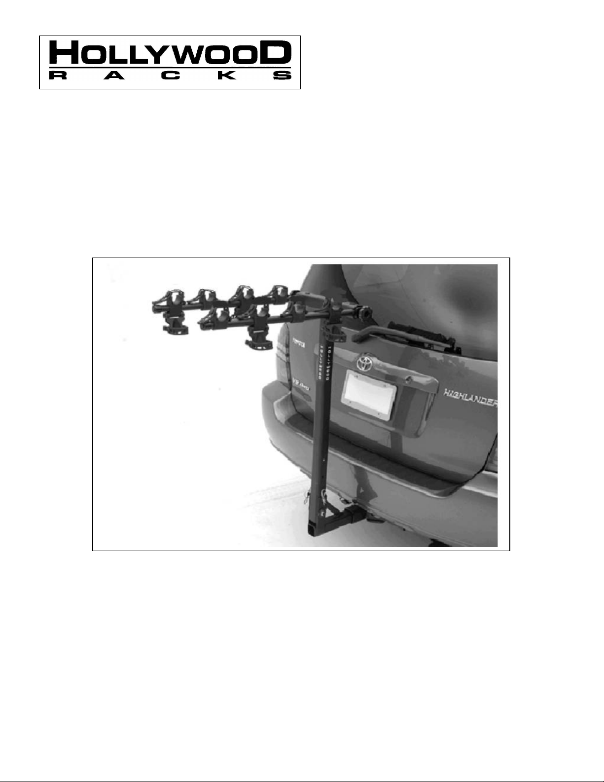
Traveler Hitch Rack
Traveler
¾” head through bolt, large washers and
Assembly and Use Instructions for Traveler Series Racks
HR6000 3-Bike Rack for 2” receiver HR6100 3 Bike Rack for 1-1/4” receiver
HR8000 4 Bike Rack for 2” receiver HR8100 4 Bike Rack for 1-1/4” receiver
HR9200 5 Bike Rack for 2” receiver
Warning! This product NOT to be used on any trailer or trailered vehicle.
Drive slowly when using the rack on bumpy or dirt roads.
Check the rack bikes and straps regularly during use.
If you have any questions or installation problems, please see your Hollywood Racks retailer or
contact Hollywood Engineering at 800-747-4085.
After opening the
should have the following parts:
1. Parts bag including two male knobs
and two spacer blocks. (Fig. 1)
.2. Parts bag including: threaded hitch
pin, hitch pin clip, star and flat washers,
self-fastening (nyloc) nut. (Fig. 2)
3. Hitch Insert Tube (Fig. 3 ) and Upright beam assembly
4. Two Support arms with bike cradles and anti-sway blocks attached (Fig. 5 and 6).
5. One long attachment/safety strap (86” long) – Not shown.
box, you
Page 2
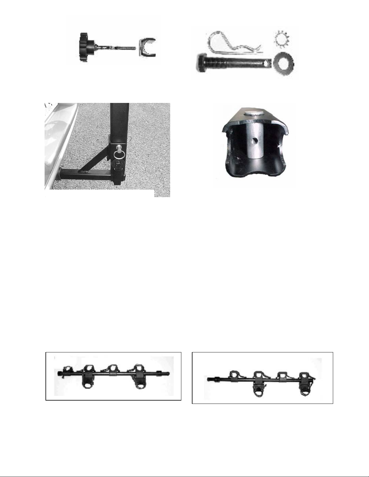
FIG. 1:
Black Knob with threaded
rod attached and pivoting spacer
FIG. 2:
Clockwise from upper left,
washer and threaded hitch pin.
block.
hitch pin clip, star washer, flat
Fig. 3 Insert tube (1-1/4” shown)
Fig. 4 Vertical Cylinder
Tools required: 2 adjustable wrenches or two ¾” wrenches (open, box or socket).
1. The rack is easily assembled on your workbench or any flat surface. To assemble the rack, lay
the upright beam face down on the bench (Hollywood sticker facing down). Place the insert
tube’s bracket onto the end of the upright beam so that the insert tube is pointing up.
2. Place a washer on the end of the through bolt, then insert the bolt through the lower hole of this
bracket, and pass it through the lower hole of the upright beam. We keep our hole tolerances
fairly tight, so you may have to wiggle it through. Once the bolt is protruding through the other
side of the bracket, install the other washer and nut. Tighten the nut securely using your
adjustable wrenches or ¾” wrenches. Insert the lynch pin through the upper hole, then install the
lynch pin clip.
3. Insert the knob through the spacer as shown in Fig. 1 (the knob should be against the flat end of
the spacer block). Align the threaded hole in the vertical cylinder (fig. 4) so that it faces out. You
can rotate the vertical cylinder using a coin or flat blade screwdriver in the slot at the top of the
vertical cylinder. Insert the knob through the support arm, and thread the knob into vertical
cylinder inside the main top horizontal tube. Repeat for the Driver’s side arm.
FIG. 5 Driver’s Side Support Arm
FIG. 6 Passenger’s Side Support Arm
Page 3

Installing the Traveler rack on your vehicle:
4.
VERY IMPORTANT!
Attach the long (86”) strap
front and rear wheels of all
while in transit). Wrap the Safety strap around the
wheels of the bikes.
1. Within the parts bag, locate the hitch pin, flat and star washers and clip (Fig. 2). The hitch pin
may be black or silver.
2. When inserting the rack into the trailer hitch, try to get the insert tube as parallel to the receiver
hitch as possible, then slide the rack in a couple of inches until the hole on insert tube of the rack
lines up with the hole in your receiver.
3. Slide the flat and lock (star) washers over the threaded hitch pin, then Insert the hitch pin through
the trailer hitch (receiver) and insert tube.
4. Thread the hitch pin into insert tube using a ¾” wrench (box, open end or socket type) or an
adjustable wrench. Tighten securely.
5. Install the hitch pin clip provided by placing it through the hole at the end of the hitch pin. To lock
the rack to your vehicle, you can alternately place a padlock through the hole at the end of the
threaded hitch pin. If you use a padlock, the hitch pin clip will not be used.
Installing your bikes on the Traveler rack:
1. If the support arms are not already in a horizontal position, back off the knob at the end of the
rack’s support arms, pull out the support arms and rotate them into the horizontal position. Retighten
the knobs securely.
2. For ease of installation, we suggest you put the
larger bikes on the inside (closest to vehicle),
smaller frames or kids bikes on the outside. The
first bike loaded should have the handlebars facing
towards the driver’s side of the vehicle. Place the
top tube (or closest appropriate frame tube) onto the
bike cradles, pull the straps over the bike tube and
attach to the tab on the opposite side of the cradle.
Use a strap notch-hole that provide a snug fit, but
take care not to pull the strap over-tight. This can
put undue stress on the bike’s paint, and may overstretch the strap, making it more susceptible to
breakage. Be sure to use the anti-sway blocks
(below the support arms) to strap the bikes seat tube
(or other frame tube as appropriate) to prevent the
bikes from swaying on the Traveler rack. The anti-
sway pivot block can be removed with either Phillips
screwdriver or 5mm hex wrench (depending on
fastener used by factory).
3. If you can’t mount the bikes top tube onto
the cradles, use the down tube or seat tube.
Secure the bike with the cradle straps. Please
note that the cradles can be rotated on the
support arm to place them in a more easily
useable position, and to accommodate unique
bicycle frame designs.
by placing it through the
bikes mounted (this keeps the wheel from spinning
main beam of the rack after passing it through the
Page 4

Special Fitting Note
: In some situations,
rticularly with very small bikes, or bikes with
sway block, so
Secure the strap by placing the end through the
center slot in the buckle, then around the bend
and out through the outer slot. Pull on the end of
Limited Lifetime Warranty (effective January 1, 2008):
n incorrect assembly, incorrect installation onto the vehicle, installation on a
If a product is believed to be defective, the original retail purchaser should contact either the original retailer or Hollywood
ther person is excluded. This warranty is expressly made in lieu of any and all other express warranties, whether
the strap until snug. Don’t Forget!
pa
creative frame designs (for example, “Y” and
“V” frame bikes) it may be necessary to
remove the lower anti-sway blacks. To do
this, simply use a 5mm Allen wrench to
remove the bolt that attaches the lower antisway block to the main (upper) bike cradle.
The nut is captured by the anti-
Fold arms down when not in use.
you will not need to hold the nut.
Hollywood Racks will warrant its car racks and accessories during the time that an original retail purchaser owns the
product subject to the exclusions and limitations of this warranty. Hollywood Racks will remedy defects in materials and
workmanship by repairing or replacing (at its option) a defective part or the complete rack without charge for labor or parts.
Hollywood Racks may elect (at its option) to issue a refund equal to the purchase price paid for the product.
This warranty does not cover problems caused by normal wear and tear including (but not limited to) weather, scratches,
dents, rust, accidents, unlawful vehicle operation, misuse, abuse, neglect, theft, unauthorized modifications, or unauthorized
repair. No warranty is given for defects resulting i
“no fit” vehicle, incorrect attachment of bicycles onto the rack, or overloading of the rack’s weight restrictions. This warranty
terminates if the original retail purchaser transfers the product to any other person.
Racks directly at 800-747-4085 or at info@hollywoodracks.com
Disclaimer of Liability: Repair or replacement of a defective product or the issuance of a refund or credit (as determined
by Hollywood Racks) is a purchaser’s exclusive remedy under this warranty. Damage to a purchaser’s vehicle, cargo, bicycles
and or to any o
oral or written.
Hollywood Racks shall not be liable for any direct, indirect, consequential, incidental, special, punitive or any other
damages in connection with the purchase, use or handling of this product.
Some states do not allow the exclusion or limitation of consequential or incidental damages and the above
limitation may not apply to you. This warranty gives you specific legal rights and you have other rights,
which vary from state to state.
Hollywood Racks
12812 South Spring Street Los Angeles, CA 90061
Tel (800) 747-4085 (310) 516-8600 Fax (310) 516-8955
Customer Service Hours: 7:00 AM - 3:00 PM PST M-F
info@hollywoodracks.com www.hollywoodracks.com
Made in Taiwan 022508 Rev B
 Loading...