

Page 1
OR INSTALLATION PROBLEMS,
HOLLYWOOD RACKS
Aluminum Road Runner Hitch Rack
Assembly and Installation instructions for model numbers:
Aluminum Road Runner 3 Series
HR300A - 3-bike model for 2” receiver (maximum weight of bikes 100 lbs.)
HR310A - 3 bike model for 1 ¼” receiver, class 2 (maximum weight of bikes 100 lbs.)
HR320A - 3-bike model extended for 2” receiver (maximum weight of bikes 100 lbs.)
Aluminum Road Runner 4 Series
HR400A – 4-bike model for 2” receiver (maximum weight of bikes 130 lbs.)
HR410A – 4 bike model for 1 ¼” receiver, class 2 (maximum weight of bikes 130 lbs.)
HR420A – 4-bike model extended for 2” receiver (maximum weight of bikes 130 lbs.)
WARNING! THIS PRODUCT IS NOT TO BE USED ON ANY TRAILER
PLEASE FOLLOW THESE
IMPORTANT POINTS:
DRIVE SLOWLY WHEN USING
THE RACK ON BUMPY OR DIRT
ROADS.
CHECK THE RACK, BIKES AND
STRAPS REGULARLY DURING
USE.
IF YOU HAVE ANY QUESTIONS
PLEASE SEE YOUR RETAILER
OR CONTACT US AT
800- 747- 4085.
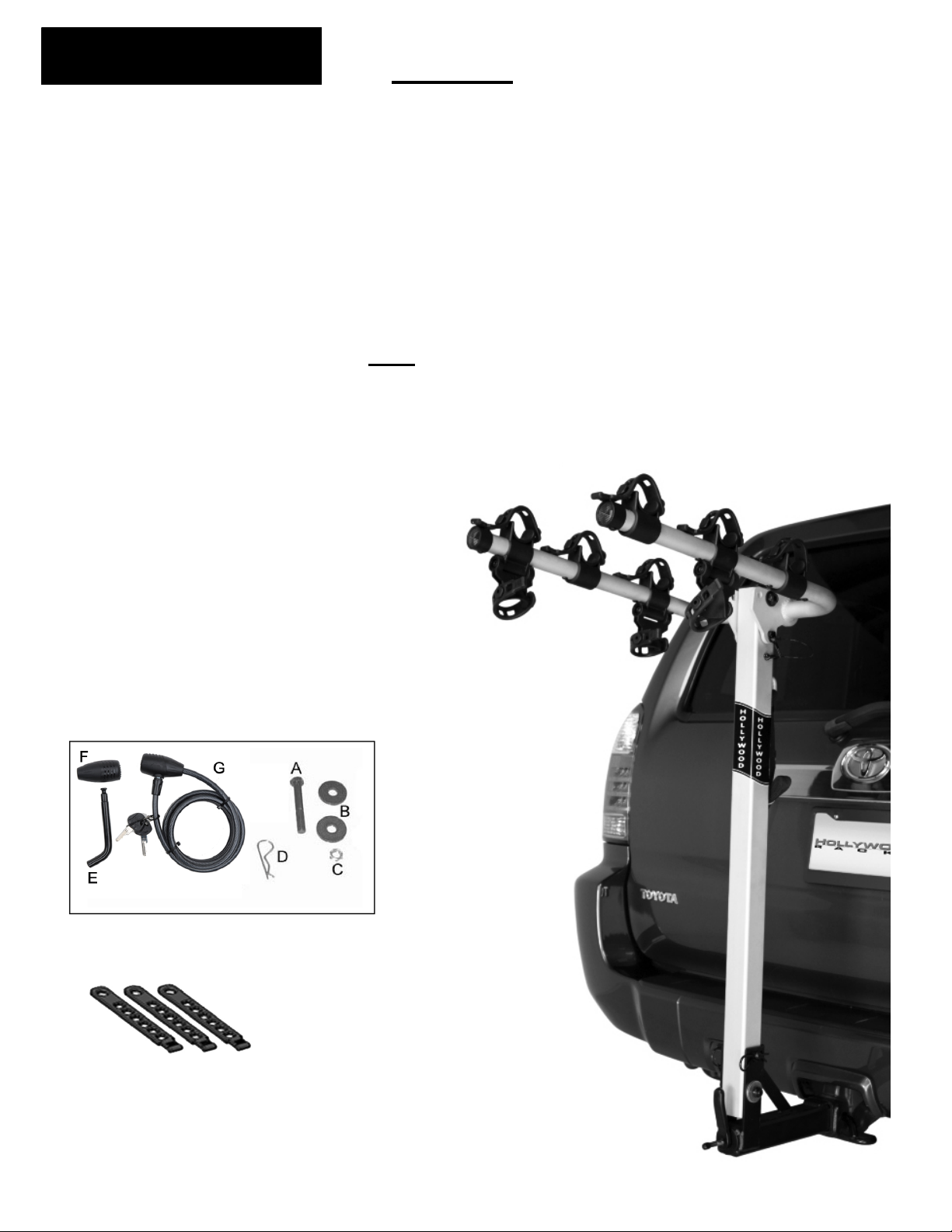
Fig. 2: Hardware Included
Fig. 3: Use 3 straps per bike
Nine straps included for 3 bike rack
Twelve straps included for 4 bike rack
Fig. 1
1
Page 2
After opening the box, you should have the following parts:
ASSEMBLY:
Tools required:
INSTALLING THE RACK ON YOUR VEHICLE:
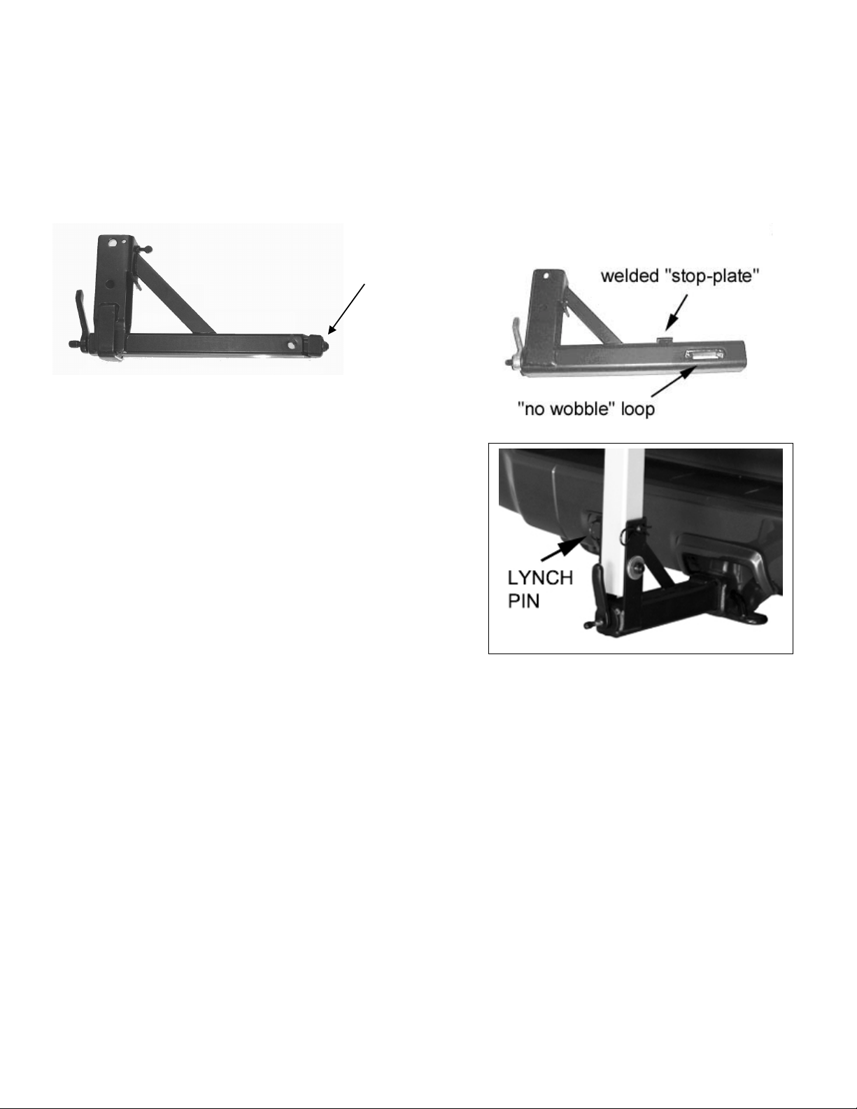
certain that the hitch pin goes through
the “loop” at the end of the “no wobble” internal threaded rod.
Fig. 5
1. Upright beam assembly with upper support arms installed.
2. Receiver tube assembly with “no wobble” system and handle lever (see below).
3. Parts bag including through bolt, washers and nut, lynch pin and clip (Fig. 2).
4. Rubber Strap bag: Road Runner 3 has 9 rubber straps, Road Runner 4 has 12 rubber straps.
There is a nylon safety strap attached to the lock-point on the back on the rack.
5. Security cable and Locking Hitch Pin (Fig. 2).
Fig. 4b 2” hitch
Fig. 4a 1 ¼” hitch
.
wedge
Two 6” adjustable wrenches or ¾” wrenches
1. The Road Runner rack is easily assembled on your
work-bench or any flat surface. To assemble the rack,
lay the upright beam face down on the bench
(Hollywood decal facing down). Place the receiver
tube’s bracket on to the end of the upright beam so that
the receiver tube is pointing up.
2. Place a washer B on the end of A, then insert the bolt
through the lower hole of this bracket and pass it through
the lower hole of the upright tube. Once the bolt is
protruding through the other side of the bracket, install
the other washer and nut C. Tighten the nut securely on
the bolt and use an adjustable wrench or ¾” wrench to tighten the nut and bolt. Insert the lynch
pin through the upper hole, and install lynch pin clip D in hole at the end of the lynch pin.
1. Within the parts bag, locate the locking hitch pin (E) and locking head (F).
2. When inserting the rack into the trailer hitch, try to get the receiver tube as parallel to the hitch as
possible. For 2” hitches (Fig. 4a) slide the rack in a couple of inches until the welded “stop-plate” on
the top of the receiver tube makes contact the outer face of your vehicle’s hitch. For 1 ¼” hitches
(Fig. 4b) align the holes of the hitch and receiver tube.
3. Unlock the Locking Hitch Pin and insert pin (E) through the trailer hitch and receiver tube. Be
2
Page 3

4. Tighten the lever clockwise to engage the patented “No Wobble” system, which will eliminate the
3
.
Installing the “safety” tie down strap:
under cables
movement of the insert tube in the receiver. The lever should be turned “up” or to the side after
tightening to prevent it from being damaged in the case you have to descend a steep driveway
or have some other close encounter with “Solid Ground.” The rack should now be attached to
your vehicle, and locked into place.
Fig. 6 folded position
INSTALLING BIKES ON THE RACK:
Fig. 7 in use position
1. Remove the lynch pin (7a), and rotate the support arms into the horizontal or “in-use” position.
Re-insert the lynch pin and attach safety clasp.
2. For ease of installation, we suggest you put the bigger bikes on the inside (closest to vehicle),
smaller frames or kids bikes on the outside. The first bike loaded should have the handlebars facing
towards the driver’s side of the vehicle. Place the top tube (or closest appropriate frame tube) onto
the bike cradles, install the straps over the bike tube and attach to the anchor tabs on both sides of
the cradle. Use a strap notch-hole that provides a snug fit, but take care not to pull the strap overtight. This can put undue stress on the bike’s paint, and may over-stretch the strap, making it more
susceptible to breakage. Be sure to use the Anti-Sway blocks (below the support arms) to strap the
bikes seat tube (or other frame tube as appropriate) to prevent the bikes from swaying on the Road
Runner rack. See fig. 8 and 9 below - Be careful not to over-stress the straps!
Route rubber straps
Fig. 8
After all the bikes have been installed, take the remaining woven
and wrap it around the rack’s upright tube and through all of the
bike’s frames. Tighten this strap securely
Fig. 9
3
Page 4

5. Anti-Theft Security
Hollywood Racks 12812 S. Spring St. Los Angeles, CA 90061 www.hollywoodracks.com
Customer Service: M
-
F 8:00 A
M
–
3:00 PM PST
Made in Taiwan
123009 rev e
Limited Lifetime Warranty (effective January 1, 2008):
For anti-theft security, the rack comes with a keyed alike locking hitch pin and a security cable G with
an integrated lock. Wrap the cable around the bike frames, their wheels and through the rack. Secure
by inserting end of cable in the lock.
6. Removing Rack and Bikes:
To remove the bikes, simply undo the straps and gently lift the bikes off. If you’re in a parking lot,
be sure to fold down the support arms to minimize the length of the rack when not in use. To remove
the rack from the vehicle, fold the support arms and lower brace, and remove the Locking Hitch Pin.
Unscrew (counter-clockwise) the “no wobble” lever and slide the rack out of the hitch receiver.
7. Backing out of driveways and going over bumps
Please keep in mind that when transporting bikes, you will be carrying more weight on your hitch.
This means the rear of your vehicle will be lower to the ground. When going up driveways or over
bumps, drive slowly and at an angle if possible. If you have
a car or minivan where the hitch is low to the ground, the rack
may hit the ground. Go slowly and please be sure the handle
lever for the no wobble system is turned up or to the side.
8. Tilting the rack down:
Refer to Fig. 5 (page 2): Remove lynch pin clip and
lynch pin to tilt the rack down for easy access to the
rear of your vehicle.
Fig. 10
Hollywood Racks will warrant its car racks and accessories during the time that an original retail purchaser owns the
product subject to the exclusions and limitations of this warranty. Hollywood Racks will remedy defects in materials and
workmanship by repairing or replacing (at its option) a defective part or the complete rack without charge for labor or
parts. Hollywood Racks may elect (at its option) to issue a refund equal to the purchase price paid for the product.
This warranty does not cover problems caused by normal wear and tear including (but not limited to) weather,
scratches, dents, rust, accidents, unlawful vehicle operation, misuse, abuse, neglect, theft, unauthorized modifications,
or unauthorized repair. No warranty is given for defects resulting in incorrect assembly, incorrect installation onto the
vehicle, installation on a “no fit” vehicle, incorrect attachment of bicycles onto the rack, or overloading of the rack’s
weight restrictions. This warranty terminates if the original retail purchaser transfers the product to any other person.
If a product is believed to be defective, the original retail purchaser should contact either the original retailer or
Hollywood Racks directly at 800-747-4085 or at info@hollywoodracks.com
Disclaimer of Liability: Repair or replacement of a defective product or the issuance of a refund or credit (as
determined by Hollywood Racks) is a purchaser’s exclusive remedy under this warranty. Damage to a purchaser’s
vehicle, cargo, bicycles and or to any other person is excluded. This warranty is expressly made in lieu of any and all
other express warranties, whether oral or written.
Hollywood Racks shall not be liable for any direct, indirect, consequential, incidental, special, punitive or any other
damages in connection with the purchase, use or handling of this product.
Some states do not allow the exclusion or limitation of consequential or incidental damages and the above limitation may
not apply to you. This warranty gives you specific legal rights and you have other rights, which vary from state to state.
(800) 747-4085 or (310) 516-8600 FAX (310) 516-8955 info@hollywoodracks.com
4
 Loading...