

Hollywood Racks HR2500 User Manual
Commuter 2 Bike Hitch Rack
PLEASE FOLLOW THESE IMPORTANT POINTS:
RETAILER OR CONTACT US AT 800
-
747-4085
.
HOLLYWOOD RACKS
Assembly step 1:
Attach Lower
5. Tighten securely using a
wrench.
Assembly and Installation instructions
WARNING! THIS PRODUCT IS NOT TO BE USED ON ANY TRAILER
DRIVE SLOWLY WHEN USING THE RACK ON BUMPY OR DIRT ROADS.
CHECK THE RACK, BIKES AND STRAPS REGULARLY DURING USE.
IF YOU HAVE ANY QUESTIONS OR INSTALLATION PROBLEMS, PLEASE SEE YOUR
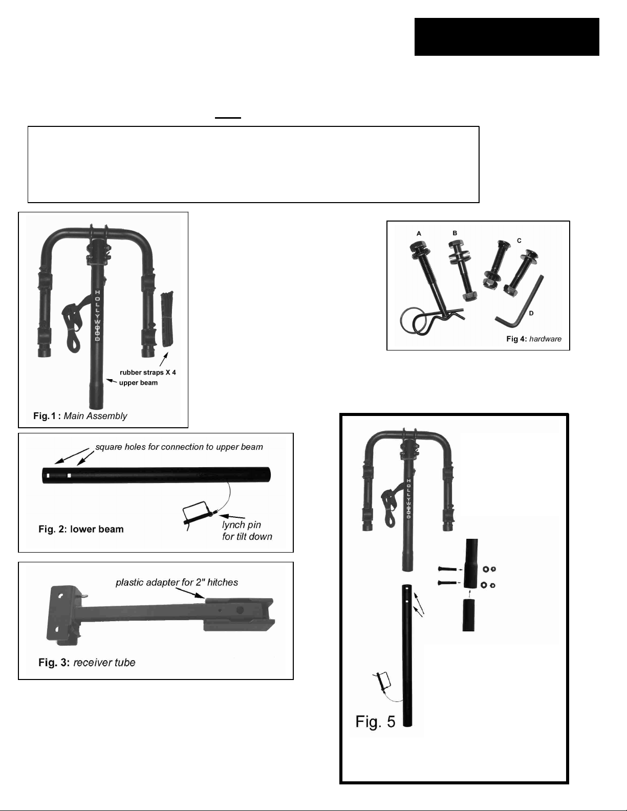
Commuter Rack box contents:
1. Main Assembly per Fig. 1
2. Lower Beam per Fig. 2
3. Receiver Tube per Fig. 3
4. Hardware bag per fig. 4, including
4A: Threaded hitch pin bolt, washer,
lock-washer and “R” clip
4B: ½”-20 bolt, nut & washers for
connection of lower beam to receiver
tube.
4C: Two 5/16”-18 carriage bolts, nuts &
washers for connection of upper beam
to lower beam.
4D: Allen key for receiver tube adapter
Tools required: two adjustable wrenches.
beam to
Upper beam
1. Insert the lower beam’s
side with 2 square holes
into the upper beam.
2. Align the holes.
3. Insert carriage bolts (C)
through holes.
4. Install washers and
nuts.
1
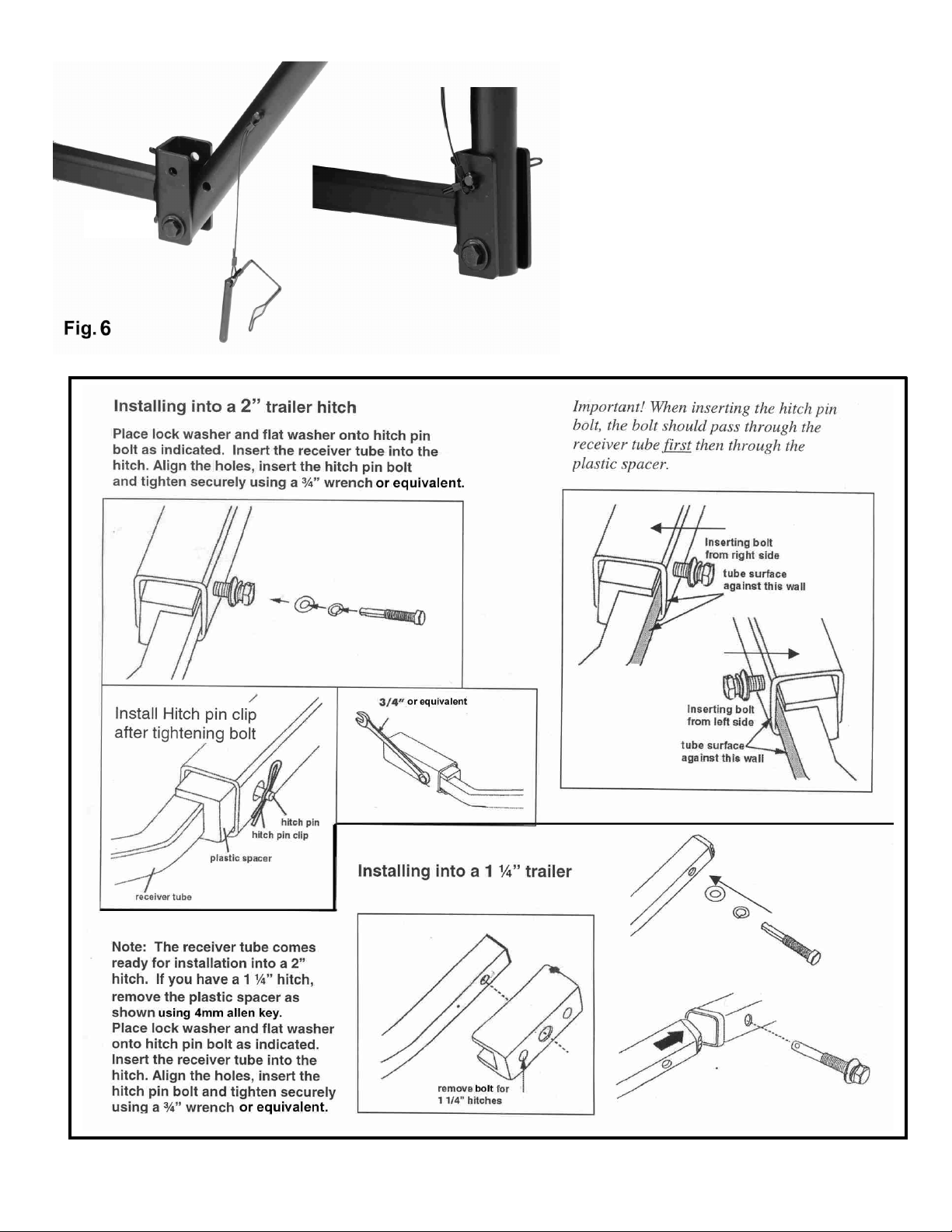
Assembly step 2:
Attach receiver tube
Fig. 6a
Fig 6b
1. Locate ½” bolt, washers and
locknut (B).
2. Place a washer on the end of the
bolt, and insert through the lower
hole of the receiver tube’s bracket
and lower beam as shown in fig. 6a.
3. Attach other washer to bolt end,
and install nut. Tighten nut onto bolt
end using both wrenches.
4. Insert “lynch pin” through upper
holes of bracket and tube, then
fasten clasp on the pin per fig. 6b.
2
 Loading...