

Hollywood Racks HR1600 Assembly And Installation Manual
Hollywood Racks RV Rider E-Bike Hitch Rack Model No. HR1600
Assembly and Installation Guide
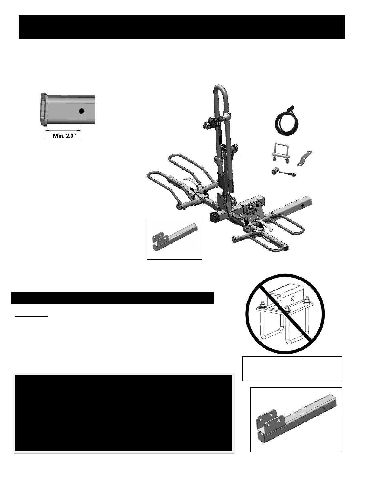
For use on 2” (min. Class III) hitches
only*. Do not use a 1 ¼” - 2” hitch
adapter. See below for other
restrictions.
Maximum weight per bicycle is 80 lbs.
Maximum bicycle wheelbase 60”.
Fits up to 3” wide tires. For fat tire
models, please see page 10.
(see page 8 for bike frame fit notes)
Not intended for use with motorized
bicycles, mopeds or motorcycles
For further video assembly &
installation instructions, please visit
hollywoodracks.com
*For 2.5” hitches, use the Hollywood
Racks hitch adapter HA-2
RESTRICTIONS – PLEASE READ BEFORE INSTALLATION
DO NOT USE WITH BUMPER MOUNTED HITCH
RECEIVER ADAPTERS!
RATED FOR USE WITH MOTOR HOMES (CLASS A, B, C), FLAT
TOWING AND 5TH WHEELS. IF FLAT TOWING, YOUR TOWED
VEHICLE MUST HAVE A MINIMUM CLASS III RECEIVER HITCH. DO
NOT USE A 1 ¼”-2” ADAPTER ON YOUR TOWED VEHICLE.
1
Rated for use with motor homes and for flat towing. See
recommendations for use with 5th wheels. Do not use with toy
haulers, travel trailers, pop-up or camping trailers.
5TH WHEEL REQUIREMENTS:
1. TRAILER HITCH MUST HAVE A MIN. 350 LBS TONGUE WEIGHT CAPACITY
2. DOUBLE AXLE AND 24’ IN LENGTH (BOX LENGTH)
3. MINIMUM GVW IS 5000 LBS
4. USE HITCH TUBE “TT” (NO FOLD UP FEATURE) HIGHLY RECOMMENDED.
THIS PRODUCT NOT WARRANTED IF ABOVE RESTRICTIONS ARE NOT
FOLLOWED. NOT WARRANTED FOR USE WITH TOY HAULERS, SINGLE AXLE
TRAILERS, TRAVEL TRAILERS, CAMPING OR POP-UP TRAILERS.
TRAVEL TRAILER
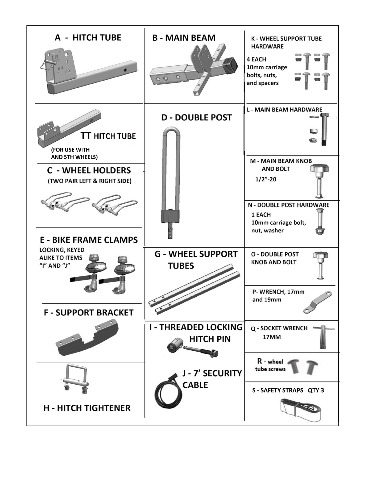
HITCH TUBE “TT”
PLEASE SEE PAGE 12 (BACK
PAGE) BEFORE INSTALLATION
2
2 each: ½-20 bolts,
nuts, washers,
1 each: spacer
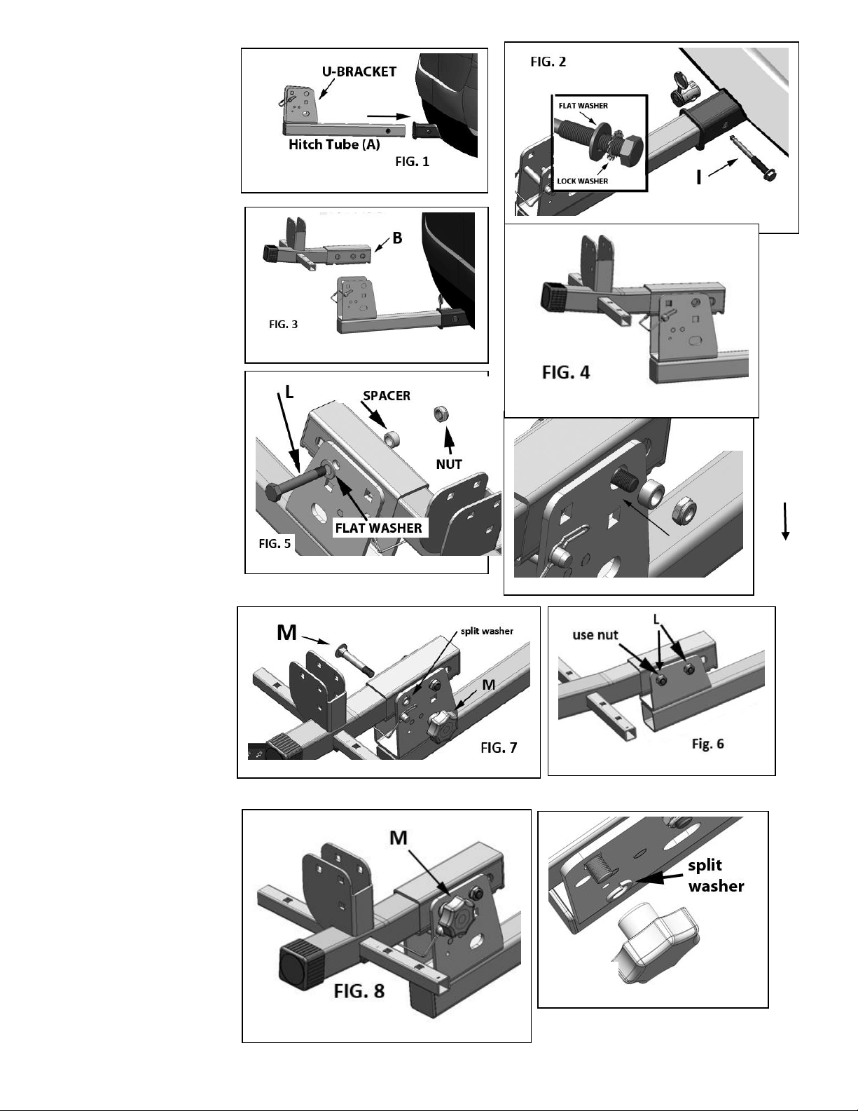
Section 1: Assembly
(adjustable wrench or ¾”
socket wrench and Phillips
screwdriver required)
Fig. 1: Install hitch tube (A)
into your vehicle’s 2”
receiver. Use “TT” hitch tube
for 5th wheels. See Fig. 6
below.
Fig. 2: Install ½-13 threaded
hitch pin (I) through the
hitch tube and receiver.
Tighten using the provided
wrench (P) or ¾” socket
wrench. Lock washer & flat
washer per Fig. 2A.
Fig. 3 & 4: Position main
beam (B) inside the hitch
tube’s large U-bracket and
align the holes.
Fig. 5: Slide the flat washer
onto pivot bolt (L), then
insert the pivot bolt so it
passes through both the
main beam and U- shaped
bracket.
Fig. 6: Slide the spacer onto
the bolt, then install the nut
onto the bolt. Tighten
securely using wrench (P)
and an adjustable or ¾”
socket wrench.
Fig. 7: Insert carriage bolt
(M) through the square hole
in the U-bracket and pass it
through the main beam until
it protrudes on the other
side of the U bracket.
Fig. 8A: Slide the split washer
onto the bolt.
Fig. 8: Install the knob for
bolt (M). Tighten securely.
3
Fig. 8A
Fig. 5A
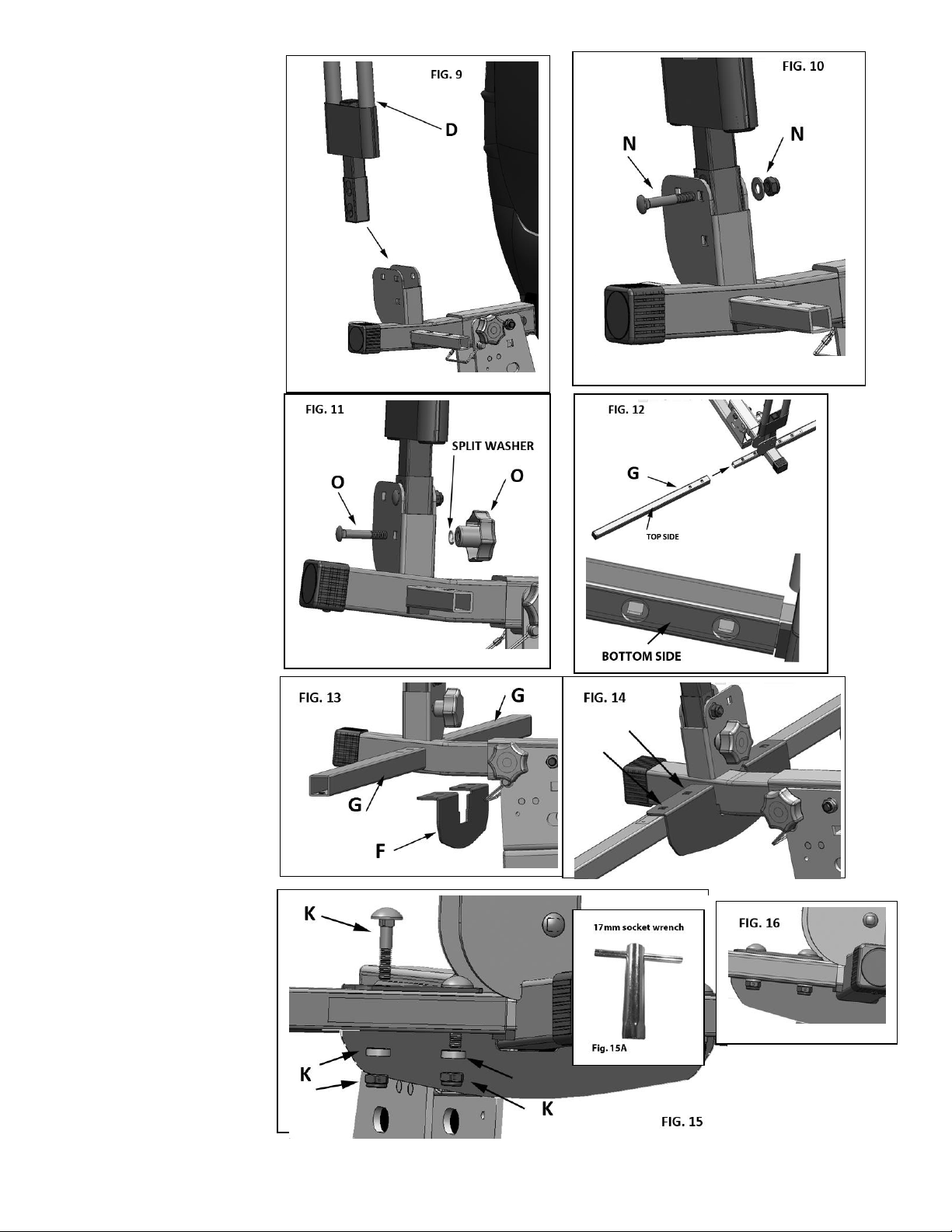
Fig. 9: Position double post
(D) in the bracket of the
main beam (B).
Fig. 10: Insert carriage bolt
(N) in the upper hole, then
install flat washer and nut
onto the bolt. Use wrench
to tighten the nut.
Fig. 11: Insert carriage bolt
(O) through the lower
hole, then install split
washer and knob onto the
bolt. Tighten knob
securely.
Fig. 12: Slide wheel tubes
(G) onto posts of main
beam. Square holes of
wheel tubes (G) are on
top, large round holes on
the bottom side.
Fig. 13: Position support
bracket (F) onto wheel
tubes. Align the square
holes per Fig. 14
Fig. 15: Insert carriage
bolts (K) from the top
through the support brace
and wheel tubes. Ends of
bolts should now be
protruding on the lower
side of the wheel tubes.
Slide the spacers up and
onto the end of the bolt.
Install and “finger tighten”
the nuts.
Fig. 16: Use socket wrench
(Q) to tighten the nuts
securely.
4
 Loading...