

Page 1
Model HR1450R Sportrider
Not to be used on any trailer, fifth wheel or vehicle being towed by another vehicle
Hollywood Racks
Recumbent Hitch Rack
for 2” hitches only
Weight Limit: 90 lbs
Maximum capacity: two 2-wheel bicycles (45 lbs each)
Not warranted to be used for carrying electric or motorized bicycles or motorcycles
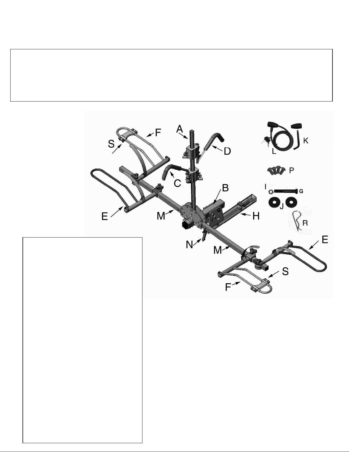
BIKE RACK PARTS LIST
Item Description Qty
A vertical post 1
B base assembly 1
B1 Front Cap 1
C short hook clamp 1
D “Z” hook clamp 1
E left wheel holder* 2
F right wheel holder* 2
G pivot bolt 1
H receiver tube 1
I pivot nut 1
J pivot washers 2
K locking hitch pin 1
L security cable 1
M wheel support tube 4
N extension lever 1
P “stop” screws 4
R clip 2
S Small Wheel Adapter 2
T hex key 1
U Tie down straps 2
*Extra wide for recumbents
Page 2
Assembly Instructions:
Tools Required: Two 8” adjustable
wrenches or equivalent, Phillips
screwdriver.
For ease of assembly, we suggest
that you use your vehicle’s hitch.
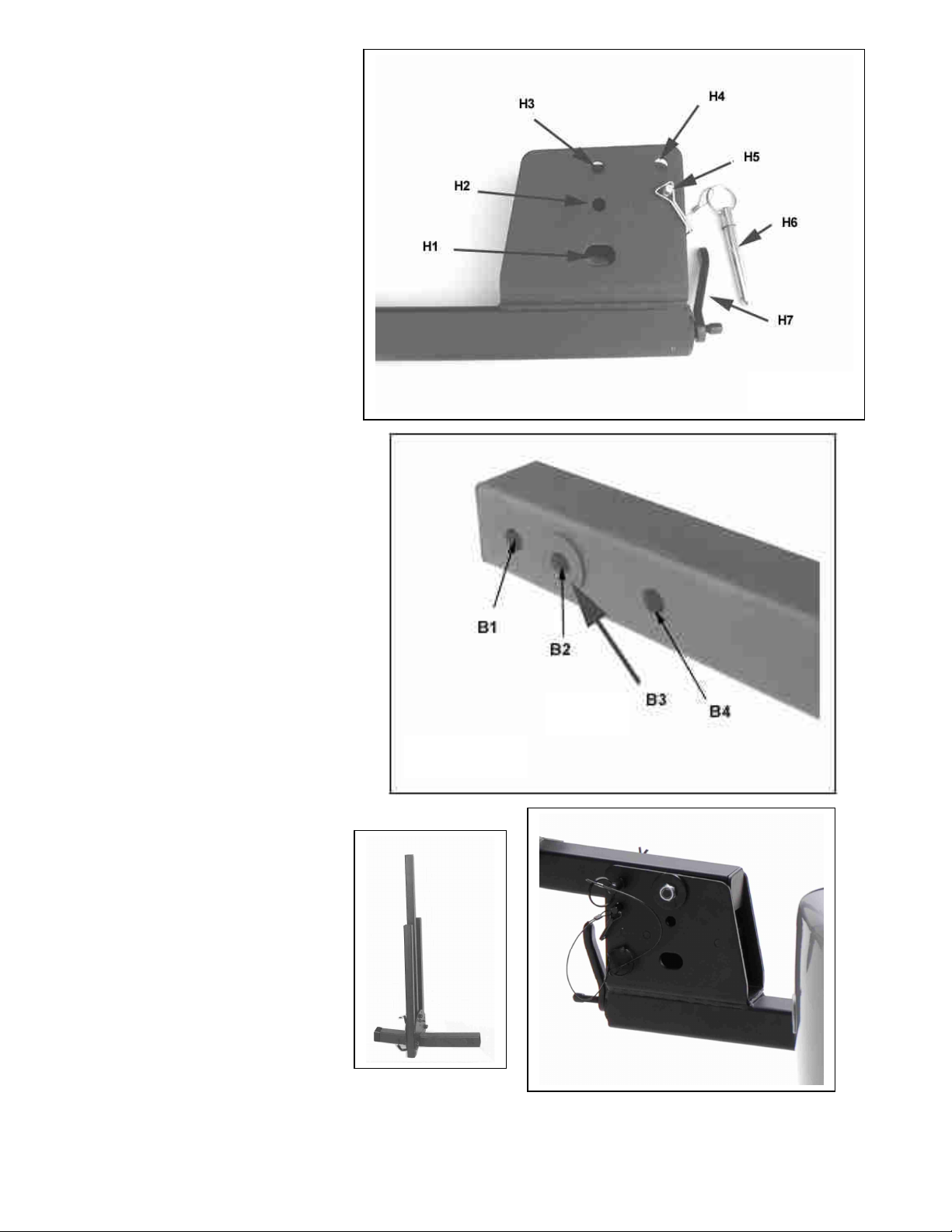
1: Assemble Receiver Tube
to Base Assembly
1. Install your receiver tube H
into the hitch. Unlock hitch pin
K and insert it through hole in
the hitch and the rack. Be sure that
the pin passes through the welded
loop on the end the bolt attached to
the lever H7. Tighten the lever H7
on the front of the insert tube until
good and snug. Use this same
procedure when using the rack.
2. Gently insert Base Assy B into
the bracket of Receiver tube H,
aligning holes H3 with B2. The
main beam can rest on pin H5.
There are two plastic washers (B3)
attached to main beam B, please
take care not to accidentally scrape
them off during assembly. Insert
pivot bolt G with washer J through
holes, then place the other washer
J on end of bolt and hand tighten
nut I.
3. Insert pin H6 through holes H4
and B4.Then install clip R through
the pin. The main beam will now be
in a fixed Horizontal position.
Tighten bolt G and nut I securely
with wrenches.
Fig. 1a
Fig. 1b
4. After tightening, remove clip R &
Pin H6 and rotate Main Beam B
into a folded (vertical) position.
Insert pin H6 through holes H2 to
check alignment. Main beam
should be able to rotate easily, but
not be too loose.
5. Remove pin H6 and rotate main
beam back to its horizontal position
to continue assembly.
Fig. 1c
“B” base assembly
Fig. 1d
Page 3

2: Install Wheel Holders:
Rotate and remove L pins from holes A. Rotate wheel
Item P
3.
Small Wheel Adapter
Fig. 2a
After installing wheel holders, install the “stop”
tubes to a horizontal position, then replace L pins into
holes B as indicated.
Slide wheel Holders E and F onto wheel tubes as
indicated.
screws (item P) into the bottom of the wheel
tubes as indicated in Figure 2d & 2e. Use
Phillips screwdriver.
Fig. 2c
For bikes with 16” wheels, use the “small wheel” S
adapter to prevent the wheel from falling through the
wheel holder. Place the upper section on top of the
wheel holder, then position the bottom section directly
below it. Insert the bolts and lightly tighten using the
included 5mm hex wrench T. Slide the wheel adapter to
the desired position then tighten all 4 bolts securely.
Fig. 2d
Fig. 2e
Fig. 3
3
Page 4

5:
Fold
U
p feature
s
6.
Tilt
–
Down Feature:
4: Installation and operation of Clamp System
Fold Together Feature
(Fig.
5c)
Position the first frame hook on top of
the round vertical post facing the
vehicle. Squeeze the lever and the
tab together, so that the lever is all the
way up (engaged). Now wiggle the
Fig. 4a
Fig. 4b
plastic housing down onto the tube
aligning the index guides with the
index slots. You may have to gently
tap it with your other hand.
Remember the lever must be
engaged to install it onto the tube.
Repeat for the second hook facing in
the opposite direction.
Using the clamps:
After the clamp is installed, it can
only be raised by engaging the
lever. The clamp can physically be
pushed down without engaging the
lever but it is highly recommended
that the lever also be engaged when
lowering the clamp.
Fig. 4c
Fig. 4d
Fig. 5c
To fold up the main beam, you
must first fold down the vertical
post (B). Refer to Fig. 5b:
Rotate and remove pin A, then
rotate the post (B) and replace
the pin in either holes C.
Next, refer to Fig. 1a: remove
clip R from pin H6, then
remove pin H6.
Finally, rotate main beam
upward and re-install pin H6
and clip into hole H2 per Fig.
1a & 5a
Fig. 5b
Fig. 5a
For easy access to the rear
cargo door of your vehicle,
the Sport Rider can be tilted
down: First fold down vertical
Post as described in “Fold-up
feature”. Next refer to fig. 1a:
Remove pins H5 then H6
from receiver tube bracket
and gently lower the main
beam down so it is resting on
the welded stop.
The rack’s wheel support tubes can
be rotated to the side as an
alternative way of folding up the
rack. Referring, remove pin from
hole D and rotate the wheel tube so
it is pointing upwards, align holes E
and re-insert the pin. Repeat for
other side.
Fig. 6
4
Page 5

Step
7
: In
stalling bikes on the rack
The bikes should be mounted from inside (1stbike) to
the outer bike. The bikes should always be positioned so that
the lowest point on the bike frame’s top tube is close to the
vertical post In the case of long wheel base recumbents, wheels
must not exceed width of side view mirrors. Please note in
some states, wheels must not exceed width of vehicle body.
The bike handlebars should be staggered (first bike’s
handlebars on passenger side, second bike’s handlebars on
driver side, etc.
Lower the vertical post. To adjust the bike’s wheels trays,
loosen the knobs and slide wheel holders along the wheel
support tube so that they are positioned directly beneath each
wheel. Tighten knobs securely after determining correct
position. Rotate the bike’s pedals so that the vertical post can
be raised and secured. Slide the hook down onto the frame.
Use the Velcro strap on the wheel holder per Fig. 7b.
Follow same procedure for second bike. After both bikes are
mounted and secured to the rack, use the additional tie down
straps (item U) to secure bike to rack per Fig. 7C
Tips for carrying woman’s bikes and bikes with slanted top
tubes: Adjust the wheel trays so that the hook will rest in the
bike frame’s top tube and seat tube.
A keyed trailer hitch pin and security cable is included to
help prevent theft of rack and bikes.
Fig. 7b
Fig. 7a
Fig. 7c
5
Page 6

Trike Adapter Optional Accessory (sold separately)
Trike Adapter Model 1: Allows the carrying of one trike only on the rack
Trike Adapter Model 2: Allows the carrying of one trike plus one bike (standard or recumbent)
Model 1 Model 2
Limited Lifetime Warranty (effective January 1, 2008):
Hollywood Racks will warranty its car racks and accessories during the time that an original retail purchaser owns the product
subject to the exclusions and limitations of this warranty. Hollywood Racks will remedy defects in materials and workmanship by
repairing or replacing (at its option) the complete rack or a defective part without charge for labor or parts. Hollywood Racks may
elect (at its option) to issue a refund equal to the purchase price paid for the product.
This warranty does not cover problems caused by normal wear and tear including (but not limited to) weather, scratches, dents,
rust, accidents, unlawful vehicle operation, misuse, abuse, neglect, theft, unauthorized modifications, or unauthorized repair. No
warranty is given for defects resulting in incorrect assembly, incorrect installation onto the vehicle, installation on a “no fit” vehicle,
incorrect attachment of bicycles onto the rack, or overloading of the rack’s weight restrictions. This warranty terminates if the
original retail purchaser transfers the product to any other person.
If a product is believed to be defective, the original retail purchaser should contact either the original retailer or Hollywood Racks
directly at 800-747-4085 or at info@hollywoodracks.com
Disclaimer of Liability: Repair or replacement of a defective product or the issuance of a refund or credit (as determined by
Hollywood Racks) is a purchaser’s exclusive remedy under this warranty. Damage to a purchaser’s vehicle, cargo, bicycles and
or to any other person is excluded. This warranty is expressly made in lieu of any and all other express warranties, whether oral
or written.
Hollywood Racks shall not be liable for any direct, indirect, consequential, incidental, special, punitive or any other damages in
connection with the purchase, use or handling of this product. Some states do not allow the exclusion or limitation of
consequential or incidental damages and the above limitation may not apply to you. This warranty gives you specific legal rights
and you have other rights, which vary from state to state.
Hollywood Racks
12812 S. Spring St. Los Angeles, CA 90061
Tel (310)516-8600 (800)747-4085 FAX (310)516-8955
www.hollywoodracks.com email: info@hollywoodracks.com
Customer Service Hours: M-F 8:00AM to 3:00 PM PST
Made in Taiwan
6
 Loading...