

Hollywood Racks HR1450 User Manual
Hollywood Racks Sport Ride
r Hitch Rack Instruction Manual
Model HR1450 - 2 Bike Capacity, 2” receiver (4 bike capacity when used with HR1475 two bike add on kit)
Not to be used on any
trailer, fifth wheel or vehicle
being towed by another
vehicle
Weight Limit 45 lbs/20 kg
per bike
2 bike maximum capacity
4 bike maximum capacity
when used with HR1475
two bike add on kit (sold
separately)
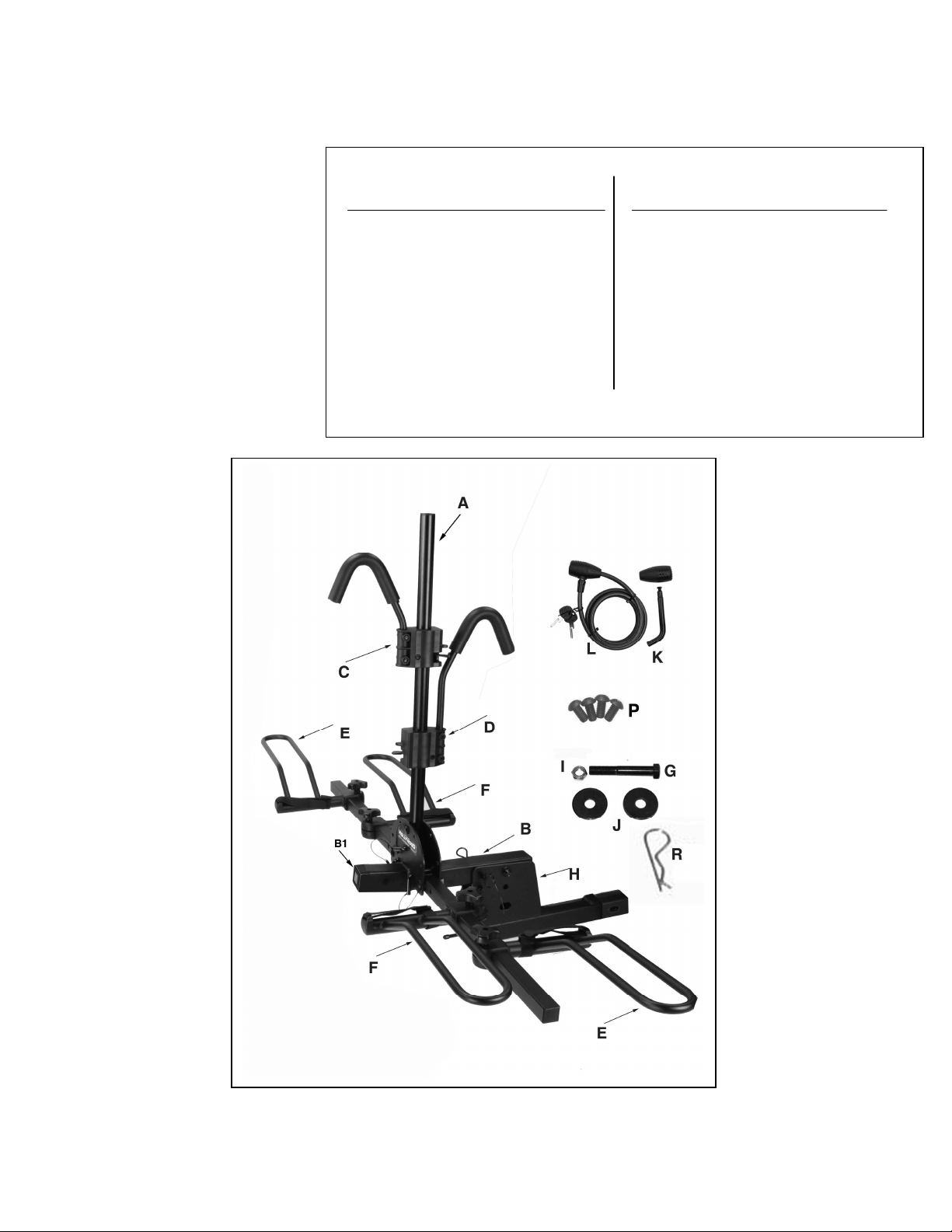
PARTS LIST
Item Description Qty Item Description Qty
A vertical post 2 H receiver tube 1
B base assembly 1 I pivot nut 1
B1 Front Cap 1 J pivot washers 2
C short hook clamp 2 K locking hitch pin 1
D long hook clamp 2 L security cable 1
E left wheel holder 4 M wheel support tube 4
F right wheel holder 4 N extension lever 1
G pivot bolt 1 P “stop” screws 2
R clip 2
Assembly Instructions:
Tools Required: Two 8” adjustable
wrenches or equivalent, Phillips
screwdriver.
For ease of assembly, we suggest
that you use your vehicle’s hitch.
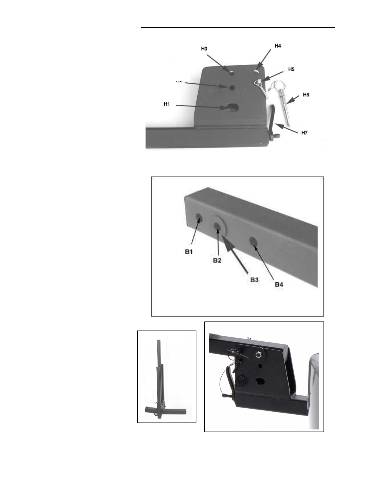
Step 1: Assemble Receiver Tube
to Base Assembly
1. Install your receiver tube H
into the hitch. Unlock hitch pin
K and insert it through hole in
the hitch and the rack. Be sure that
the pin passes through the welded
loop on the end the bolt attached to
the lever H7. Tighten the lever H7
on the front of the insert tube until
good and snug. Use this same
procedure when using the rack.
2. Gently insert Base Assy B into
the bracket of Receiver tube H,
aligning holes H3 with B2. The
main beam can rest on pin H5.
There are two plastic washers (B3)
attached to main beam B, please
take care not to accidentally scrape
them off during assembly. Insert
pivot bolt G with washer J through
holes, then place the other washer
J on end of bolt and hand tighten
nut I.
3. Insert pin H6 through holes H4
and B4.Then install clip R through
the pin. The main beam will now be
in a fixed Horizontal position.
Tighten bolt G and nut I securely
with wrenches.
Fig. 1a
Fig. 1b
4. After tightening, remove clip R &
Pin H6 and rotate Main Beam B
into a folded (vertical) position.
Insert pin H6 through holes H2 to
check alignment. Main beam
should be able to rotate easily, but
not be too loose.
5. Remove pin H6 and rotate main
beam back to its horizontal position
to continue assembly.
Fig. 1c
“B” base assembly
 Loading...