

Page 1
Sport Rider
Instruction Manual
O
HOLLYWOOD RACKS
B
1
B2
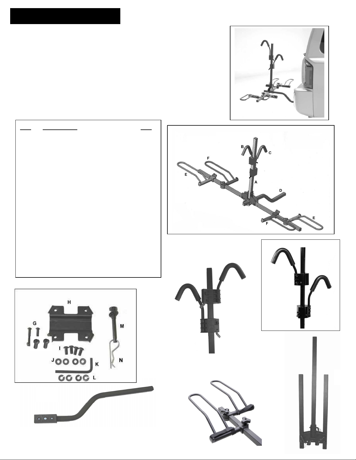
Model HR1000 – 2 Bike Hitch Rack
with ratcheting hooks OR Precision Slide Clamps
Not to be used on any trailer, fifth
wheel or vehicle being towed by
another vehicle
Weight Limit 45lbs/20 kg per bike
2 bike maximum capacity
Optional locking kits available
ID# Description Qty
A MAIN RACK ASSY 1
B1 Ratchet style short frame hook OR
B2 Precision slide short frame hook 1
C1 Ratchet style long frame hook OR
C2 Precision slide long frame hook 1
D RECEIVER TUBE & SPACER 1
E LEFT SIDE WHEEL TRAY 2
F RIGHT SIDE WHEEL TRAY 2
G REC. TUBE STOP BOLTS 2
H LOWER BRACKET 1
I 8MM BOLTS 4
J FLAT WASHERS 4
K 5MM HEX KEY 1
L LOCK WASHERS 2
M ½-13 THREADED HITCH PIN 1
N HITCH PIN CLIP 1
P WHEEL TUBE STOP SCREWS 2
Pour instructions en Français, continuer aux pages 8 et 9.
D
C1
C2
A
F
E
1
Page 2
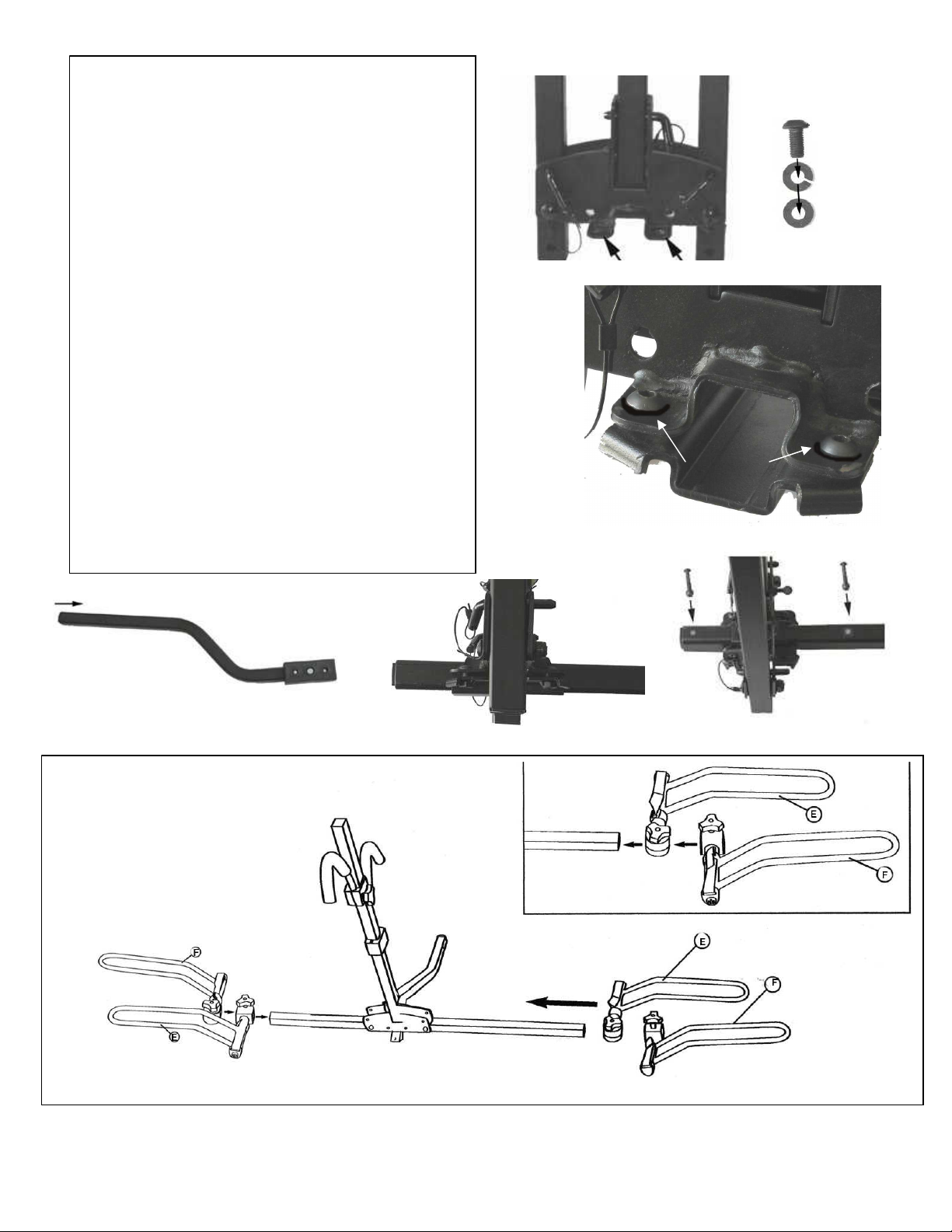
Fig. 1
Assembly & Installation Procedure:
Step 1: Locate holes on main rack assembly,
bracket and hardware (Fig. 1)
Step 2: Loosely assemble bracket to main
rack as shown in Fig. 2 & 3. Bolts (I) inserts
through lock washer (L), then flat washer (J),
then top plate and into bottom plate Do Not
tighten!
Step 3: Slide main rack assembly onto
Receiver tube as shown in Fig. 4 & 5.
Adjust position so that is 3 or 4 inches
between the end of the rack and end of the
receiver tube. Tighten using hex wrench
provided or equivalent. Note: Final position
of vertical portion of the rack can be readjusted after you have installed the rack on
your vehicle
Step 4. Insert “stop bolts” (G) through hole in
receiver tube as indicated.
See Fig. 6.
Fig. 2
Fig. 3
washers
Fig. 4
Step 5a: Install Wheel holders:
Fig. 5
Fig. 6
Fig. 7
Page 3
Step 7A: Install frame hooks:
Step
6
:
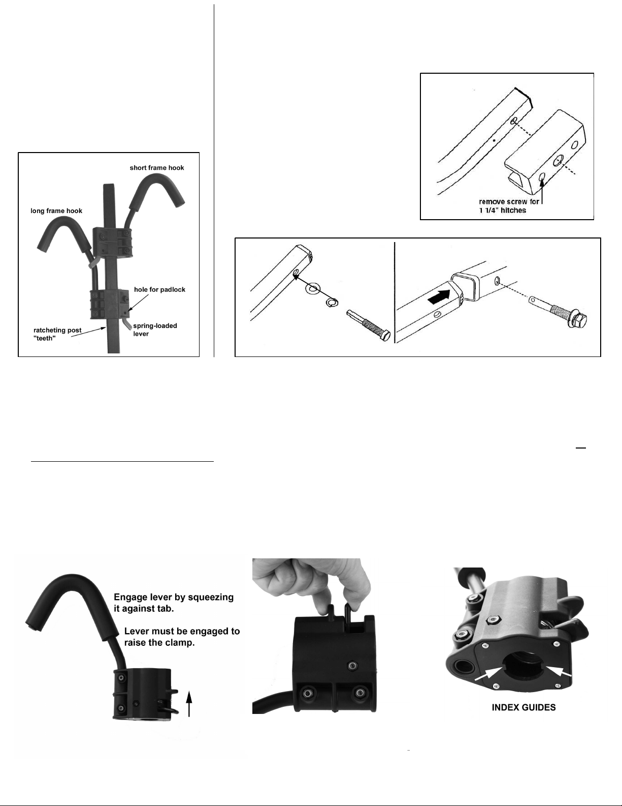
Installing into a 1 ¼” trailer
Note: The receiver tube comes
using a ¾” wrench.
For ratchet style hooks only:
Slide long frame hook down
vertical post facing vehicle.
Then slide short frame hook
onto post, facing away from
vehicle. You should hear be able
to hear the spring loaded lever
engaging the teeth on the post
as shown in fig. 8.
Fig. 8
ready for installation into a 2”
hitch. If you have a 1 ¼” hitch,
use the provided hex wrench to
remove the plastic spacer as
shown in Fig. 9.
Place lock washer and flat washer
onto hitch pin bolt as indicated.
Insert the receiver tube into the
hitch. Align the holes, insert the
hitch pin bolt and tighten securely
Fig. 9
Fig. 10
Fig. 11
7B: For Precision Slide style clamps only
Installation and operation of “Precision-Slide” Clamp System
Install the clamps on the vertical post:
Position the long frame hook on top of the round vertical post facing the vehicle. Squeeze the lever and the tab together, so
that the lever is all the way up (engaged). Now wiggle the plastic housing down onto the tube aligning the index guides with
the index slots. You may have to gently tap it with your other hand. Remember the lever must be engaged to install it
onto the tube. Repeat for the short hook facing in the opposite direction.
Using the clamps:
After the clamp is installed, it can only be raised by engaging the lever. The clamp can physically be pushed down
without engaging the lever but it is highly recommended that the lever also be engaged when lowering the clamp.
Squeeze lever all the way, lever
must be completely engaged.
3
Page 4

Step 6 B: Installing into a 2”trailer hitch
Fig. 13
Fig. 14
Fig. 15
Folding Down Vertical Post
16b
16a
Place lock washer and flat washer onto hitch pin
bolt as indicated. Insert the receiver tube into the
hitch. Align the holes, insert the hitch pin bolt
and tighten securely using a ¾” wrench.
Fig. 12
Important! When inserting the hitch pin
bolt, the bolt should pass through the
receiver tube first then through the
plastic spacer.
Install Hitch pin clip
after tightening bolt
For easy access to the cargo area, the vertical post can
be folded down. To fold down vertical post, rotate and
remove the side-retaining pin as shown in Fig. 16a-16d.
Be sure to re-tighten the thumbscrew after replacing pin.
16d
16c
Page 5

Folding Up the Wheel Holders
To fold up the wheel holders, rotate and remove
the front retaining pins. Then rotate the tube up
and re-install the pins. See Fig. 17a &17b
17a
17b
Installing Bikes on the Rack
Pre-position the wheel trays to fit the bike’s wheel base (center to center distance between the wheel axels) such
that they are directly beneath each wheel. To adjust the wheel trays, loosen the knobs and slide along the wheel
holder support tube. Tighten knobs securely.
To fit the first bike (closest to the vehicle) more easily, the vertical post may be tilted down (away from vehicle).
To do this, simply remove the side retaining pin per. Note: Never fold down main tube with bike(s) mounted. Place
the first bike in the wheel holders, and then rotate the vertical post up per Fig 16d. Handlebars for the first bike
should be on the driver’s side of the vehicle. If carrying two bikes, always load the smaller bike first (position the
smaller bike between the vehicle and vertical post)
Be sure that the hooks are well supported on the bike’s frame. Push hook firmly down onto bike frame as shown
in Fig 18d. Try pulling up on the hook to be sure the clamp is properly engaged. Use the Velcro strap on the
wheel holder as the final step of installing the bikes on the rack, per Fig. 18e.
Repeat for the outside/second bike with the short hook.
Page 6

Tips for carrying
woman’s bikes and
Double check before driving off
Optional accessories
Final Step:
Fig. 20a
Fig. 20b
bikes with slanted
top tubes
Adjust the wheel
trays so that the
hook will rest in the
bike frame’s top tube
and seat tube, as
shown in Fig. 19a
and 19b.
19a
18e
18d
To release the frame
hook, depress the
Lever and pull the
hook up.
Tip: you may have
to push the hook
down a bit while
holding in the lever
to release it.
19b
Install wheel tube stop screws: After you have installed the
bikes on the rack and are comfortable with the positions of the wheel holders,
the stop screws can be installed. Locate items P from hardware bag. Thread
them into the hole located on the bottom of wheel tubes (Fig. 20), and tighten
with a flat edge screwdriver. The screws are removable.
- Knobs are tight on all four wheel trays and
- Frame hooks are pushed all the way down
- All three retaining pins are properly inserted and secure
- Wheel straps are fastened
- Hitch pin is secure and hitch pin clip is installed
- Drive slowly on bumpy or dirt roads
for your Sport Rider
:
Locking Threaded
hitch pin with
security cable
part no. LHPTC
Locking threaded
hitch pin
part no. LHPT
Page 7

Limited Lifetime War
ranty (effective
January 1, 2008):
Hollywood Racks will warrant its car racks and accessories during the time that an original retail purchaser owns the product subject
to the exclusions and limitations of this warranty. Hollywood Racks will remedy defects in materials and workmanship by repairing or
replacing (at its option) a defective part or the complete rack without charge for labor or parts. Hollywood Racks may elect (at its option)
to issue a refund equal to the purchase price paid for the product.
This warranty does not cover problems caused by normal wear and tear including (but not limited to) weather, scratches, dents, rust,
accidents, unlawful vehicle operation, misuse, abuse, neglect, theft, unauthorized modifications, or unauthorized repair. No warranty is
given for defects resulting in incorrect assembly, incorrect installation onto the vehicle, installation on a “no fit” vehicle, incorrect
attachment of bicycles onto the rack, or overloading of the rack’s weight restrictions. This warranty terminates if the original retail
purchaser transfers the product to any other person. If a product is believed to be defective, the original retail purchaser should contact
either the original retailer or Hollywood Racks directly at 800-747-4085 or at info@hollywoodracks.com
Disclaimer of Liability: Repair or replacement of a defective product or the issuance of a refund or credit (as determined by Hollywood
Racks) is a purchaser’s exclusive remedy under this warranty. Damage to a purchaser’s vehicle, cargo, bicycles and or to any other
person is excluded. This warranty is expressly made in lieu of any and all other express warranties, whether oral or written.
Hollywood Racks shall not be liable for any direct, indirect, consequential, incidental, special, punitive or any other damages in
connection with the purchase, use or handling of this product. Some states do not allow the exclusion or limitation of consequential or
incidental damages and the above limitation may not apply to you. This warranty gives you specific legal rights and you have other
rights, which vary from state to state.
Hollywood Racks
Quality bicycle racks since 1973
12812 S. Spring St. Los Angeles, CA 90061
Tel (310) 516-8600 (800) 747-4085 FAX (310)516-8955
www.hollywoodracks.com email: info@hollywoodracks.com
Customer Service Hours: M-F 8:00AM to 3:00 PM PST
Made in Taiwan 061010 rev. F
7
Page 8

Hollywood Sport Rider.
8
Modele HR1000 Porte-vélo pour atelage remorque pour 2 vélos.
e pas utiliser ce produit sur une remorque ou un véhicule qui est remorqué.
mite de poids par vélo de 45lbs ou 20 kgs
apacité maximum 2 vélos
Ref Description des pièces Quantité
A Cadre principal 1
B Crochet court 1
C Crochet long 1
D Tube pour l’attelage remorque 1
E Support roue gauche 2
F Support roue droite 2
G Boulon pour extremite de D 1
H Attache inferieure 1
I Boulons de 8mm 4
J Rondelles 4
K Clefs de 5mm 1
L Rondelles de sécurité 2
M ½-13 Cheville anti-jeu 1
N Agrafe pour cheville anti-jeu 1
O Boulons pour tube de support roués 2
Assemblage et procédure d’installation
1. Trouver les trous sur le cadre principal A, attache inferieure H et boulons et rondelles I et J (Fig 1 et 2)
Attacher légèrement A et H avec I et J comme sur Fig.3. Ne Pas serrer!
2. Glisser le Tube pour l’atelage remorque D entre A et H comme sur la Fig 5. Ajuster la position pour que
la distance entre l’extrémité de D et l’extrémité de l’ensemble A et H soit de 3 ou 4 pouces. Serrer
fermement avec la clef K ou equivalent. Note: la position verticale de l’ensemble peut être ré-ajusté
après avoir installé le Sport Rider sur le véhicule.
3. Inserrer le boulon G à l’extremité de D (Fig 6)
4. Installation des crochets. Glisser le long crochet C le long du mât central, crochet court vers le véhicule.
Ensuite glisser le crochet court B le long du mât central, crochet vers l’exterieur ou l’arrière. Vous
devriez entendre les cliquements du levier avec resort s’engageant sut le mât comme sur Fig.8
6A Installation du tube de l’attelage pour attelage de 1-1/4”
Note: La pièce D est prête pour l’attelage de 2”. Si vous avez l’attelage pour 1-1/4”, utiliser la clef K
pour enlever la pièce en plastique comme sur la Fig 9. Placer la rondelle de blocage et la rondelle plate
sur la cheville anti-jeu (Fig 10). Inserrer le Porte-vélo dans l’attelage. Aligner les trous et inserrer la
cheville anti-jeu et serrer fermement avec une clef de ¾” (Fig 11).
6B Installation du tube de l’attelage pour attelage de 2”.
Placer la rondelle de blocage et la rondelle plate sur la cheville anti-jeu (Fig 12). Inserrer le Porte-vélo
dans l’attelage. Aligner les trous et inserer la cheville anti-jeu et serrer fermement avec une clef de ¾”
(Fig 14).
Important! La cheville doit passer en premier à travers le tube métallique de l’atelage avant la pièce en
plastique (Fig 13)
Page 9

Inclinaison du mât central.
For un accès facile a la porte arrière, le mât central s’incline en tournant et en enlevant la broche
comme sur Fig 16a-16d. Assurez vous de reserrer la vis après avoir redresser le mât.
Rangement des support de roues
Pour ranger les supports de roues, tounez et enlevez les broches de devant. Fig 17a & 17b.
Installation et opération de l’attache “Precision-Slide”
Etape 1: Installer l’attache “Precision Slide” sur le mât central
Positioner le crochet long D a l’extrémite du mât central vers le véhicule. Dépresser le levier et le rebors pour que le levier soit tout en
haut (engagé). Inserer la partie en plastique à travers le mât central de façon à ce que les guides indéxés soit dans la rainure du mât.
Attention le levier doit être engagé sur le mat.
Etape 2:Utilisation des attaches
Après que les attaches soient installées, elles ne peuvent se remonter que si le levier est depressé. L’attache peut être
poussée vers le bas mais nous recommandons de dépresser le levier dans les deux sens. Se référencer au
manuel d’instruction pour positioné les crochets sur les velos
Installation des vélos sur le Porte-vélo
Pré-positioner les supports de roues E et F à la distance du centre de chaque roue de chaque vélo. Pour
ajuster les supports de roues, deserrer les molettes, faire glisser les supports de roues le long des tubes
pour les supports de roues. Reserrer les molettes fermement (Fig 18a)
Pour monter le premier vélo vers le véhicule, le mât central peut être incliné Fig 16a-16d. Le guidon du
premier vélo devrait être du côté du conducteur. Si vous portez 2 vélos, toujours charger le vélo le plus
petit d’abord (entre le véhicule et le mât central).
Baisser les crochets sur le cadre fermement comme sur Fig 18d. Essayer de releverf le crohet pour
d’assurrer que les dents du levier soient bien engages. Toujours utiliser les sangles en Velcro pour les
roues du vélo.
Répèter pour le deuxième vélo (côté exterieur du mât).
Important: Pour les vélos femmes/ mixte ou avec cadre avec tube central incliné.
Ajuster les supports de roues de façon à ce que le crochet soit à l’intersection sur le cadre du tube de
selle et du tube central incliné (Fig 19a)
Etape finale: Installer les boulons pour les supports roues: Après avoir monte les vélos sur le
Sport Rider, les boulons P doivent être intallés a l’extrémité et au dessous des tubes de support de roues
Fig.20a et 20b
Vérifier Les choses suivantes avant de partir.
Molettes bien serrées pour les supports de roues et les crochets
Toutes les broches soient proprement inserrées et securisées.
Les sangles pour les roues soient bien attachées.
Cheville anti-jeu et attache pour cheville soient bien installées
Conduire doucement sur chaussée en mauvais état ou chemin de terre.
Important:
Le fabriquant de ce produit n’est pas responsible des dommages causés par le mauvais usage
de ce produit. C’est la responsabilité de l’utilisateur de s’assurer que le porte vélo
est monté proprement sur le véhicule et que les vélos soient proprement chargés sur
le porte vélo comme decrit dans ces instructions d’installation.
9
 Loading...