

Page 1

TX1 He OPERATING MANUAL
TX1 He
DIVE COMPUTER
OPERATING MANUAL
© 2002 DESIGN (2014)
1
Doc. 12-4101-r06 (1/21/14)
Page 2

TX1 He OPERATING MANUAL
CONTENTS
WELCOME.........................................................................................4
WARNINGS........................................................................................5
NOTICES............................................................................................6
FCC ID................................................................................................6
FEATURES & FUNCTIONS............................................................7
ABBREVIATIONS/TERMS......................................................8
DISPLAY ICONS.......................................................................9
CONTROLS..............................................................................10
BUTTON NAVIGATION.........................................................11
ACTIVATION...........................................................................12
MENU SYSTEM......................................................................12
Navigating Menus.....................................................................12
AUDIBLE ALARM..................................................................13
PC INTERFACE.......................................................................14
POWER SUPPLY.....................................................................14
Battery Icon..........................................................................14
BATTERY STATUS..................................................................14
TX1 He LOW BATTERY WHILE ON SURFACE..............15
TX1 He LOW BATTERY DURING DIVE...........................15
TMT (TRANSMITTER) LOW BATTERY...........................15
OPERATING MODES.............................................................15
TRANSITION PERIOD..........................................................16
POWER SAVER MODE (PSM).............................................16
NORM SURFACE MODES............................................................17
NORM SURF MAIN................................................................18
NORM SURF ALT SCREENS................................................18
NORM MENU..........................................................................19
GAS MENU..............................................................................19
FLY/DESAT...............................................................................19
Fly/Desat Screen....................................................................20
PLAN MENU............................................................................20
Time Limits...........................................................................20
Depth Limits..........................................................................20
NORM/GAUGE LOG.............................................................21
Log Menu............................................................................21
SET MENU...............................................................................22
OP (OPERATING) MODE.....................................................22
HISTORY (NORM/GAUGE)..................................................23
TX1 He ID.................................................................................23
BATT/TMT...............................................................................23
DIVE PREVIEW......................................................................23
GAS SUB MENUS....................................................................24
GAS SWITCH MENU.......................................................24
SELECT GASES MENU...................................................25
SET GASES.........................................................................26
TRANSMITTERS
SET TRANSMITTER MENU....................................27
SET SERIAL NUMBER (CODE) SCREEN.............27
SET GROUPS
SET A (ALARMS)..............................................................28
SET U (UTILITIES)...........................................................29
SET SAFETY STOP....................................................29
SET GF (GRADIENT FACTOR)...............................30
SET T (TIME/DATE)........................................................31
SET S (SHORTCUT).........................................................31
SET D (DIVE MAIN)........................................................32
SET P (PREVIEW)............................................................33
DIVE MODE FEATURES...............................................................34
PROXIMITY OF THE TMTS AND TX1 He........................35
Link Interruption Underwater............................................35
WET ACTIVATION.................................................................36
SMARTGLO® BACKLIGHT.................................................36
BAR GRAPHS..........................................................................36
TLBG.........................................................................................36
VARI..........................................................................................36
ALGORITHM..........................................................................37
GRADIENT FACTOR (GF)...................................................37
DEEP STOP (DS).....................................................................37
SAFETY STOP (SS).................................................................38
DIVE TIME REMAINING (DTR).........................................38
No Deco DTR (NDC)........................................................38
O2 Time Remaining (OTR).............................................39
GAS TIME REMAINING (GTR)..........................................39
GTR Alarm........................................................................39
TOTAL ASCENT TIME (TAT)..............................................40
NORM DIVE OP MODE................................................................41
NORM DIVE SCREENS.........................................................42
DEEP STOP PREVIEW...........................................................43
DEEP STOP MAIN..................................................................43
SAFETY STOP MAIN.............................................................43
DECOMPRESSION.................................................................44
DECO CEILING VIOLATION (DCV).................................44
DELAYED DECO VIOLATION (DDV)................................45
DEPTH VIOLATION (DV)....................................................45
GAS SWITCH WARNING.....................................................46
HIGH PO2................................................................................46
LOW PO2.................................................................................46
HIGH 02 SATURATION.........................................................47
VIOLATION GAUGE MODE (VGM)..................................48
NORM DIVE MAIN MENU
Gas Switch...........................................................................48
Isobaric Counter Diffusion (ICD) Warning.....................48
Select Gases.........................................................................48
Depth Limits........................................................................49
Current END (w/O2 NARC Yes/No) WOB......................49
Deco Stops............................................................................50
Batt/TMT............................................................................50
GAUGE OP MODE.........................................................................51
GAUGE SURF SCREENS.......................................................52
GAUGE MENU
SWITCH TMT...................................................................53
FLY......................................................................................53
LOG.....................................................................................53
SET MENU.........................................................................53
OP MENU...........................................................................53
HISTORY............................................................................53
TX1 He ID...........................................................................53
BATT/TMT STATUS.........................................................53
DIVE PREVIEW.................................................................53
SWITCH TMT SUB MENU
GAUGE TMT SWITCH....................................................54
SEARCHING FOR TMT..................................................54
© 2002 DESIGN (2014)
2
Doc. 12-4101-r06 (1/21/14)
Page 3

TX1 He OPERATING MANUAL
SET GROUPS
SET A (ALARMS)..............................................................54
SET U (UTILITIES)...........................................................54
SET T (TIME/DATE)........................................................54
SET S (SHORTCUT) MENU............................................55
SET D (DIVE MAIN) MENU...........................................55
SET P (PREVIEW) MENU...............................................56
GAUGE DIVE SCREENS.......................................................57
GAUGE DIVE MAIN..............................................................57
GAUGE DIVE ALT..................................................................57
GAUGE CHANGE TMT SCREENS.....................................58
GAUGE TMT SWITCH..........................................................58
SEARCHING FOR TMT........................................................58
GAUGE DEPTH VIOLATION...............................................58
COMPASS MODE...........................................................................59
COMPASS DISPLAY ICONS.................................................60
OVERVIEW..............................................................................61
COMPASS MENU...................................................................61
NORTH OP MAIN...........................................................61
REFERENCE OP MAIN.................................................62
REFERENCE MENU......................................................62
Set Reference Heading.................................................62
CALIBRATION................................................................63
DECLINATION................................................................64
ALARMS...........................................................................64
REFERENCE....................................................................................65
PC INTERFACE.......................................................................66
PC REQUIREMENTS.............................................................66
CARE AND CLEANING.........................................................67
INSPECTIONS AND SERVICE.............................................67
BATTERY REPLACEMENT..................................................68
Battery Retention..............................................................68
Battery Cover Removal....................................................68
Battery Removal...............................................................68
Inspection...........................................................................69
TX1 He Battery Installation............................................69
Testing................................................................................70
TRANSMITTER BATTERY REMOVAL.............................70
TRANSMITTER BATTERY INSTALLATION...................70
Installing A Transmitter On A Regulator.......................71
Transmitter Compatibility With Nitrox.........................71
ALTITUDE SENSING AND ADJUSTMENT.......................71
RESET DURING A DIVE.......................................................71
WRIST STRAP.........................................................................72
Strap Removal...................................................................72
Strap Replacement...........................................................72
Adjusting the Shock Cord Version.................................73
TECHNICAL DATA................................................................74
Specications.....................................................................75
© 2002 DESIGN (2014)
3
Doc. 12-4101-r06 (1/21/14)
Page 4

TX1 He OPERATING MANUAL
Welcome to Hollis Gear
and
THANK YOU
for choosing the
TX1 He.
The TX1 He was designed to create a user friendly dive computer that allows the
use of Air, Nitrox, and Trimix. It is a powerful instrument indeed - with a digital
compass, gauge mode, use of up to six transmitters, Gradient Factors, Hollis Dive
Planning Software, and many more features to be discussed within. It is a tool that
will open up many underwater activities to the user.
With the use of the included Hollis Dive Planning Software and data cable, all of the
TX1 He's potential dives can be explored. It is a valuable tool to plan contingencies
and gas requirements. One can also use the software as a learning tool, exploring
different gas choices, proles, and options.
It is imperative to fully understand all the features and functions before pushing to
the limits of the TX1 He. Reaching one's own limits is more likely before reaching the TX1 He's. For this reason, do not neglect the need for proper knowledge,
training, skill, and experience before venturing into new territory. No computer can
replace those attributes.
We at Hollis wish you the best in your diving adventures.
© 2002 DESIGN (2014)
4
Doc. 12-4101-r06 (1/21/14)
Page 5

TX1 He OPERATING MANUAL
! WARNINGS !
Pay special attention to items marked with this Warning symbol.
If your TX1 He stops working for any reason while operating, it is important that you have anticipated this possibility
and are prepared for it. This is an important reason for not pushing the tables, oxygen exposure limits, and a critical
reason to avoid entering decompression, without proper training. If you dive in situations where your trip would be
ruined or your safety would be jeopardized by losing the use of your TX1 He, a backup instrument system is highly
recommended.
It is extremely important that you read this manual and understand completely before attempting to use your new
Hollis dive computer.
Each numeric and graphic display represents a unique piece of information. It is imperative that you understand the
formats, ranges, and values of the information represented to avoid any possible misunderstanding that could result
in error.
Hollis PDCs are NOT for use by commercial divers.
Hollis PDCs are intended for use by divers who have successfully completed a recognized course in SCUBA diving,
and have knowledge of the potential risks and hazards of SCUBA diving.
As with all underwater life support equipment, improper use or misuse of Hollis PDCs can result in serious injury or
death.
If you do not fully understand how to use the PDC, or if you have any questions, you should seek instruction in its
use from your Authorized Hollis Dealer before diving with it.
Remember that technology is no substitute for common sense, and a PDC only provides the person using it with
data, not the knowledge to use it. Remember also that the PDC does not actually measure and test the composition of
your body tissue and blood. Using an Hollis PDC, just as using the U.S. Navy (or other) Decompression Tables, is no
guarantee of avoiding decompression sickness. Every diver’s physiology is different, and can even vary from day to
day. No machine can predict how your body will react to a particular dive prole.
Never share or exchange a dive computer with another diver, or use another dive computer for a repetitive dive.
Special training, equipment, and support are necessary for diving deeper than the maximum recommended depth
limit for recreational diving, generally agreed to be 130 FT (39 M) by most diving instruction authorities.
Decompression diving is inherently hazardous and greatly increases your risk of decompression sickness, even
when performed according to the PDC's calculations.
Oxygen features are intended for use by divers who have successfully completed a recognized course in diving with
enriched nitrogen-oxygen (Nitrox) mixtures, and have knowledge of the potential risks and hazards of diving with
Nitrox. Maximum limits for exposure to oxygen should not be exceeded, and the consequences of CNS (Central Nervous System) Oxygen Toxicity and Pulmonary Oxygen Toxicity can be deadly.
Helium features are intended for use by divers who have successfully completed a recognized course in diving with
Trimix mixtures, and have knowledge of the potential risks and hazards of diving with Trimix.
Diving at high altitude requires special knowledge of the variations imposed upon divers, their activities, and their
equipment by the decrease in atmospheric pressures. Hollis recommends completion of a specialized Altitude training course by a recognized training agency prior to diving in high altitude lakes or rivers.
Repetitive dives in a series should only be conducted at the same Altitude as that of the rst dive of that series.
Repetitive dives made at a different Altitude will result in an error equal to the difference in barometric pressure, and
possibly a false dive mode with erroneous data.
If an Hollis PDC is activated at an elevation higher than 14,000 feet (4,270 meters), it will immediately shutdown or
revert to Watch Mode.
© 2002 DESIGN (2014)
5
Doc. 12-4101-r06 (1/21/14)
Page 6

TX1 He OPERATING MANUAL
NOTICES
LIMITED TWO-YEAR WARRANTY
For details, refer to the Product Warranty Registration Card provided.
COPYRIGHT NOTICE
This operating manual is copyrighted, all rights are reserved. It may not, in whole or in part, be copied, photocopied, reproduced, translated,
or reduced to any electronic medium or machine readable form without prior consent in writing from HOLLIS/2002 Design.
TX1 He Operating Manual, Doc. No. 12-4101
© 2002 Design, 2013
San Leandro, CA USA 94577
TRADEMARK, TRADE NAME, AND SERVICE MARK NOTICE
HOLLIS, the HOLLIS logo type, TX1 He, the TX1 He logo, Gas Time Remaining (GTR), Diver Replaceable Batteries, Graphic Diver Interface,
Tissue Loading Bar Graph (TLBG), Pre-Dive Planning Sequence (PDPS), SmartGlo, Set Point, Control Console, Turn Gas Alarm, and HOLLIS
Computer Interface (HCI) are all registered and unregistered trade-marks, trade names, and service marks of HOLLIS. All rights are reserved.
PATENT NOTICE
U.S. Patents have been issued to protect the following design features: Dive Computer with Wireless Data Transmission (U.S. Patent no.
7,797,124), Air Time Remaining (U.S. Patent no. 4,586,136 and 6,543,444) and Data Sensing and Processing Device (U.S. Patent no.
4,882,678). Set NIBG Alarm and other patents pending. User Setable Display (U.S. Patent no. 5,845,235) is owned by Suunto Oy (Finland).
DECOMPRESSION MODEL
The program within the TX1 He simulates the absorption of inert gases into the body by using a mathematical model. This model is merely a
way to apply a limited set of data to a large range of experiences. The TX1 He dive computer model is based upon the latest research and experiments in decompression theory. Still, using the TX1 He, just as using the U.S. Navy (or other) No Decompression Tables, is no guarantee
of avoiding decompression sickness, i.e. “the bends”. Every diver’s physiology is different, and can even vary from day to day. No machine
can predict how your body will react to a particular dive prole
FCC COMPLIANCE:
This equipment complies with Part 15 of the FCC Rules. Operation is subject to the following two conditions: 1.) This equipment may not
cause harmful interference. 2.) This equipment must accept any interference received, including interference that may cause undesired opera-
tion.
FCC INTERFERENCE STATEMENT:
This equipment has been tested and found to comply with the limits for an Intentional Radiator, a Class B Digital Device, pursuant to Part 15 of
FCC Rules, Title 47 of the Code of Federal Regulations. These rules are designed to provide reasonable protection against harmful interference in a commercial or residential installation. This equipment generates, uses and can radiate radio frequency energy and, if not installed
and used in accordance with the instructions, may cause harmful interference to radio communications.
There is no guarantee that interference will not occur in a particular installation. If this equipment does cause interference to radio or television
reception, which can be deter-mined by turning the equipment off and on, the user is encouraged to try to correct the interference by one or
more of the following measures:• Reorient or relocate the receiving antenna.• Increase the separation between the equipment and receiver.•
Connect the equipment to an outlet on a circuit different from that to which the receiver is connected.• Consult the dealer or an experienced
radio/TV technician.
! WARNING: Changes or modication to this unit not expressly approved by HOLLIS/2002 Design could void the
user's authority to operate the equipment.
© 2002 DESIGN (2014)
FCC ID: MH8A
6
Doc. 12-4101-r06 (1/21/14)
Page 7

TX1 He OPERATING MANUAL
FEATURES/FUNCTIONS
© 2002 DESIGN (2014)
7
Doc. 12-4101-r06 (1/21/14)
Page 8

ABBREVIATIONS/TERMS
ACTIV = Activation
AL = Alarm
ALT = Alternate
ATA = Standard Atmosphere (unit)
AUD = Audible
AVAIL = Available
BATT = Battery
CAL = Calibrate (compass)
CDT (CD) = Countdown Timer
DCS = Decompression Sickness
DECO = Decompression
DESAT = Desaturation Time
DFLT = Default
DTR = Dive Time Remaining
DURA = Duration (backlight)
E = East (compass)
EDT = Elapsed Dive Time
EL = Elevation (altitude)
END = Equivalent Narcotic Depth
FHe = Fraction of Helium (%)
FO2 = Fraction of Oxygen (%)
FORM = Format (date, time)
FT = Feet (depth)
GAUG = Digital Gauge Dive Mode
GF = Gradient Factor
GLO = Glow (backlight)
GTR = Gas Time Remaining
HCI = Hollis Computer Interface
HIST = History
HT = Hypoxic Threshold
LO = Low (battery)
M = Meters (depth)
TX1 He OPERATING MANUAL
MIN = Minutes (time)
MOD = Maximum Operating Depth
N = North (compass)
NDC = No Deco DTR
NDL = No Deco Limit
NE = Northeast (compass)
NO = Number
NORM = Normal Dive Mode
NW = Northwest (compass)
O2 = Oxygen
OTR = O2 DTR
PDC = Personal Dive Computer
PO2 = Partial Pressure of O2 (ATA)
PRESS = Pressure
PSM = Power Saver Mode
REF = Reference (compass)
S = South (compass)
SAFE = Safety (stop)
SE = Southeast (compass)
SEC = Seconds (time)
SN = Serial Number
SURF = Surface
SW = Southwest (compass)
SWCH = Switch (gas)
TAT = Total Ascent Time (deco)
TLBG = Tissue Loading Bar Graph
TMR = Timer
TMT = Transmitter
VIOL = Violation
W = West (compass)
WOB = Work Of Breathing
© 2002 DESIGN (2014)
8
Doc. 12-4101-r06 (1/21/14)
Page 9
TX1 He OPERATING MANUAL
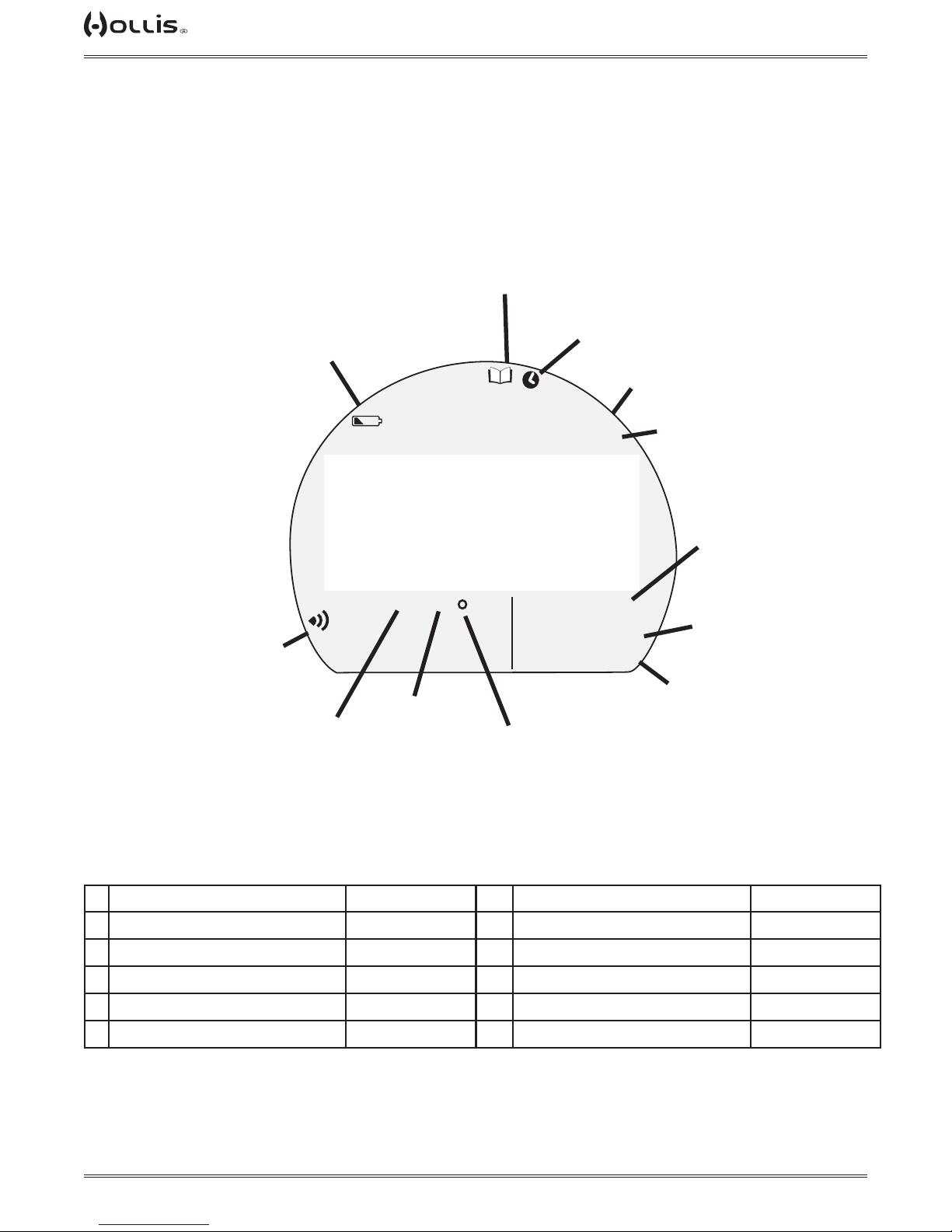
DISPLAY ICONS
2
6
1
7
Dot Matrix
PO2
BAR
8
PSI
9
3
FTM
SURF
GTR
4
TAT
min
5
12
11
10
1 Low Battery Indicator p. 15
2 Log p. 21
3 Value is Time
4 Depth ID (units) p. 29
5 Surface Interval p. 16
6 TMT Link p. 27, 35
© 2002 DESIGN (2014)
7 Value is PO
8 Pressure ID (units) p. 29
9 Temperature or Heading p. 18, 60
10 Time is Minutes
11 Total Ascent Time p. 40
12 Gas Time Remaining p. 39
9
2
p. 46
Doc. 12-4101-r06 (1/21/14)
Page 10
TX1 He OPERATING MANUAL
CONTROLS
FTM
SURF
S
TLBG
PO2
BAR
PSI
GTR
VARI
TAT
min
M
A
BUTTONS
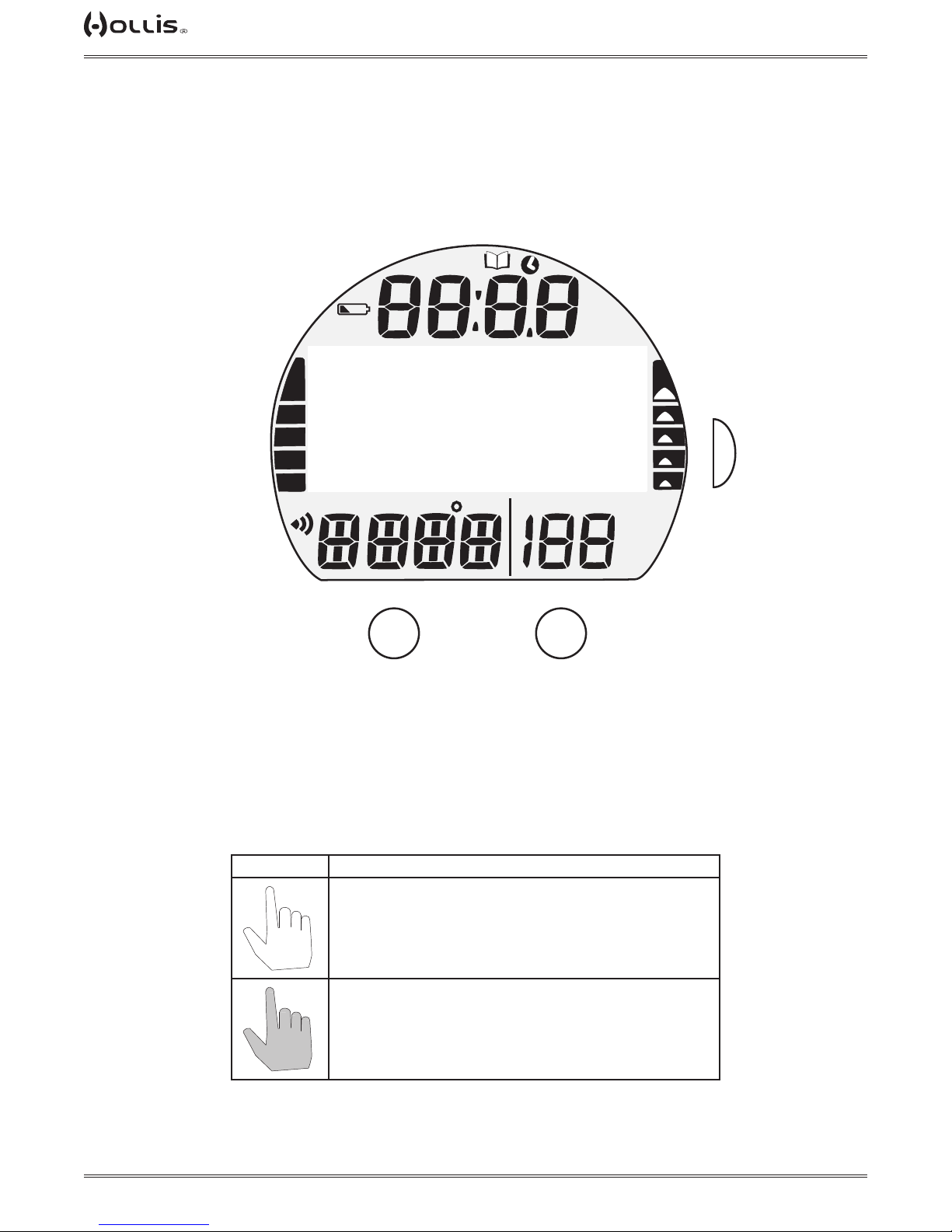
The TX1 He utilizes 3 Control Buttons that allow you to select mode options and access specic information.
They are also used to link the Transmitter(s), enter Settings, activate the Backlight, and acknowledge the Audible
Alarm. Throughout this manual they will be referred to as the M, A, and S buttons.
Pressing different combinations of these buttons will navigate through different menus and options of the TX1 He.
The symbols in the table below will illustrate how to proceed through the menus.
SYMBOL MEANING
PRESS THE BUTTON, LESS THAN 2 SECONDS, THAT THE INDEX FINGER POINTS
TO.
© 2002 DESIGN (2014)
HOLD BUTTON, GREATER THAN 2 SECONDS, THAT THE INDEX FINGER POINTS
TO.
10
Doc. 12-4101-r06 (1/21/14)
Page 11
BUTTON NAVIGATION
PRESS
TAP
TAP
ACTION BUTTON FUNCTION
Press Button Any Activate TX1 He
FTM
SURF
TLBG
PO2
BAR
PSI
M
S
VARI
GTR
TAT
min
A
M
TX1 He OPERATING MANUAL
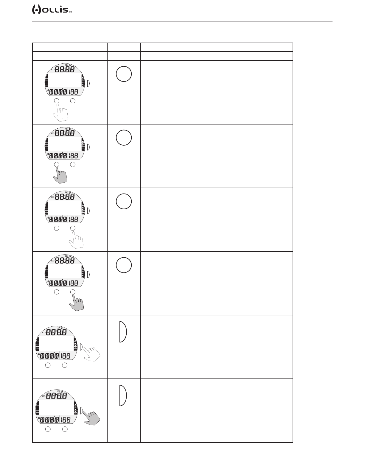
• to access Menu
• to scroll up the screen (backward) through Menu selections
FTM
SURF
• to return to Surface Main
M
TLBG
PO2
BAR
PSI
M
HOLD
TLBG
PO2
BAR
PSI
M
TLBG
PO2
BAR
PSI
M
S
VARI
GTR
TAT
min
A
FTM
SURF
S
VARI
GTR
TAT
min
A
FTM
SURF
S
VARI
GTR
TAT
min
A
A
A
• to scroll down the screen (forward) through Menu selections
• to scroll fast through set points
HOLD
FTM
SURF
TLBG
PO2
BAR
PSI
M
TLBG
PO2
BAR
PSI
M
S
VARI
GTR
TAT
min
A
FTM
SURF
S
VARI
GTR
TAT
min
A
HOLD
S
S
© 2002 DESIGN (2014)
• to select, save, or access, an item that is ashing or indicated
by an arrow icon (>)
• to activate Backlight
• acknowledge alarms (while diving)
• to step back from a Menu to a previous screen, Menu, or
Menu item
11
Doc. 12-4101-r06 (1/21/14)
Page 12
TX1 He OPERATING MANUAL
ACTIVATION
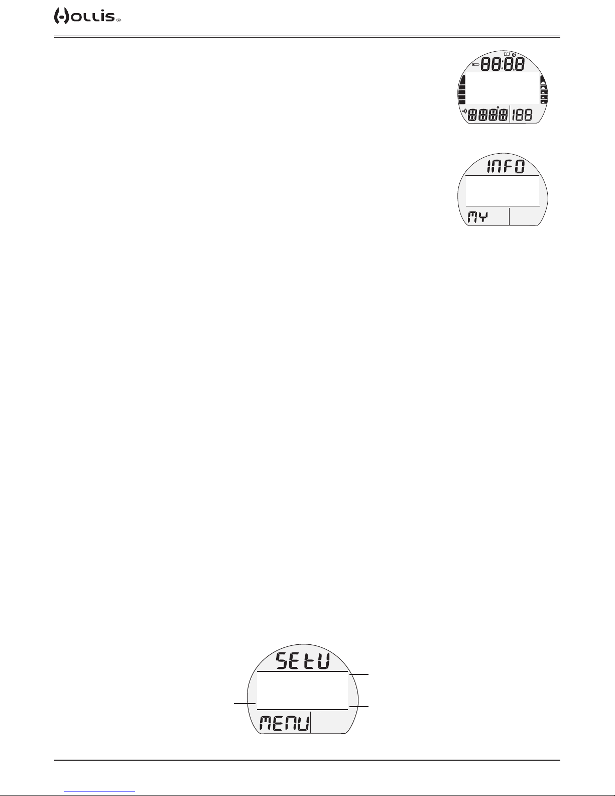
To activate the TX1 He, press/release any button.
• The unit will enter Diagnostic Mode displaying all segments of the LCD as 8's, followed by dashes ( - - ), then a countdown from 9 to 0. It checks the display and voltage to ensure that everything is within tolerance.
• It will also check ambient barometric pressure, and calibrate present depth as 0.
When at 3001 feet (916 meters), or higher, it will adjust depth for the higher altitude.
• After the Diagnostic check, a MY INFO screen will be displayed for 10 sec. showing
a default message, or information that you enter using the PC interface system.
• The NORM Surface Main screen will then be displayed, allowing access to all surface functions.
• If no dive is made within 2 hours, the unit will shut Off. Also see PSM (Power Saver
Mode) on page 16.
Contacts located on the stems of the buttons and pins of the PC Data Port will automatically activate the unit and cause it to enter dive mode when the contacts become
wet and it senses depth of 5 FT (1.5 M). They will not inadvertently activate Surface
Mode such as when in a wet gear bag.
MENU SYSTEM
The Dot Matrix located in the middle of the LCD viewing area is used to display alpha
numeric messages and measured values as well as Menu type systems for selection of settings and various auxiliary functions. It also serves as the Digital Compass
which can be accessed while viewing Main screens.
FTM
SURF
TX 1
DIAGNOSTICS
TLBG
PO2
BAR
PSI
Diagnostic Check
(for 3 seconds then My Info)
(PZ+)
CF
USE OCEANLOG
PC PROGRAM TO
ENTER YOUR DATA
TLBG
PO2
Default Message
(for 10 seconds then Surf Main)
FTM
SURF
VARI
GTR
TAT
min
GTR
TAT
min
There are multiple Menus such as -
• NORM Main Menu
• GAUGE Main Menu
• Compass Menu
• Compass Reference Menu
• Set Gases Menu
• Set Alarms Menu
• Set Utilities Menu
• Set Time Menu
• Set Shortcut Menu
• Set Dive Main Menu
• Set Preview Menu
Upon entering a Menu, movement through it starts at the rst (top) selection, then
continues in a rolling manner down the screen showing selections in groups of up to
4 items.
Navigating Menus > >
• Right Arrow icon ( > ) at the left indicates that the item can be selected.
• Down Arrow icon ( v ) at the right indicates that additional items are available below
(after) those shown.
• Up Arrow icon ( ^ ) at the right indicates that additional items are available above
(before) those shown.
This item can
be selected
(accessed).
© 2002 DESIGN (2014)
(PZ+)
FTM
CF
SET GF
O2 NARC
GLO DUR
>SAMPLE
TLBG
PO2
BAR
SURF
30-80
YES
15 SEC
60 SEC
PSI
12
>
GTR
TAT
min
>
There are more
items above.
There are more
items below.
Doc. 12-4101-r06 (1/21/14)
Page 13

TX1 He OPERATING MANUAL
AUDIBLE ALARM
While operating in NORM or GAUGE Mode the Audible will emit 1 beep per second for 10 seconds when alarms
strike, unless it is set Off. During that time, the Audible can be acknowledged and silenced by pressing the S button (less than 2 seconds).
An LED Warning Light, on the housing, is synchronized with the Audible and ashes as the Audible sounds. It will
turn Off when the Alarm is silenced. The Audible and LED will not be active if the Audible is set OFF (a group A
setting).
Alarms that strike during operations in Compass Mode are described on page 64.
Situations that will activate the NORM/GAUGE 10 second Alarm include -
* Items apply only in NORM mode.
• Gas Time Remaining (GTR) at 5 minutes, then again at 0 minutes.
• Tank Pressure at the Set Point selected.
• Descent deeper than the Depth Alarm Set Point selected.
• Dive Time Remaining at the Set Point selected*.
• Elapsed Dive Time at the Set Point selected.
• PO2 level greater than PO2 max*.
• Low PO2 Warning (0.17 ≤ PO2 < 0.21) and Low PO2 Alarm (PO2 < 0.17)
• O2 accumulation at 240 OTU (80%), then again at 300 OTU (100%)*.
• TLBG at the Set Point selected*.
• Ascent Rate exceeds 60 FPM (18 MPM) when deeper than 60 FT (18 M), or 30 FPM (9 MPM) at 60 FT (18 M)
and shallower.
• Loss of the active Transmitter Link signal for more than 15 seconds during a dive.
• Entry into Decompression Mode (Deco)*.
• Missed Deco Warning (depth is shallower than the deepest prescribed Stop Depth for < 1 minute)*.
• Missed Deco Alarm (depth is shallower than the deepest prescribed Stop Depth for > 1 minute)*.
• Deco Ceiling Violation (Gradient Factor value > 90 for < 5 minutes)*.
• Delayed Deco Violation (Gradient Factor value > 90 for ≥ 5 minutes)*.
• Depth Violation (Depth > 400 FT/120 M in NORM, > 400 FT/120 M in GAUGE).
A single short beep (which cannot be disabled) sounds when -
• After 5 minutes on the surface after the Violation dive.
3 short beeps (which cannot be disabled) sound when -
• Ascent Rate is 51 to 60 FPM (15.1 to 18 MPM) when deeper than 60 FT (18 M), or 26 to 30 FPM (7.5 to 9 MPM)
at 60 FT (18 M) and shallower.
During the following situations, the audible will not turn off when acknowledged -
• Delayed Deco Violation
• Depth Violation
© 2002 DESIGN (2014)
13
Doc. 12-4101-r06 (1/21/14)
Page 14
TX1 He OPERATING MANUAL
TAP
TAP
TAP
PC INTERFACE
Interface with a PC, to allow uploading settings and downloading data, is accomplished by connecting the TX1 He
to a PC USB Port using the special USB Interface Cable.
The software program together with the USB Driver required is on the HCI (Hollis Computer Interface) CD, and
can be downloaded from the Hollis web site. The program's HELP* serves as the user manual which can be
printed for personal use.
*Prior to attempting to Download data from your TX1 He or Upload Settings to it, review the HELP section of the
HCI program. It is recommended to print those sections of HELP that you consider appropriate for your Interface
activities.
The Settings Upload portion of the HCI program can be used to set/change the Set A group (Alarms), Set U group
(Utilities), Set T (Time), etc. using the same Interface System. FO2 and FHe related items must be set using the
control buttons.
Information available for retrieval (download) from the TX1 He to the PC Download portion of the program includes dive data such as number, surface interval time, maximum depth, elapsed dive time, no deco status, pres-
sure, start date/time, lowest temperature under water, sampling rate, dive prole, and Set Points.
The HCI program also allows upgrade of select versions of the TX1 He's rmware (operating system software) af-
ter which the TX1 He resets all operating data. Since the upgrades require reset of the TX1 He, they are blocked
during 24 hours after dives.
• Refer to page 66 for more details relating to HCI and PC Interface.
POWER SUPPLY
• TX1 He Battery >> (1) 3 vdc, CR2450, Lithium.
• Shelf life >> up to 5 years.
• Use life >> 100 dive hours if (1) 1 hour dive per dive day up to 300 dive hours if (3) 1 hour dives per dive day.
• Transmitter (each) >> (1) 3 vdc, CR2, .75 Ahr, Lithium.
• Use life >> 300 dive hours if (2) 1 hour dives per dive day.
• Replacement >> by user (annual recommended).
Battery Icon (for TX1 He only, does not apply to TMTs):
• Warning >> icon on solid when < 2.75 volts, battery change recommended.
• Alarm >> icon on ashing when < 2.50 volts, change the battery.
BATTERY STATUS
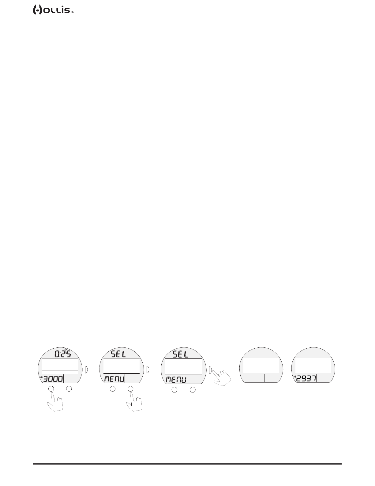
To access, while viewing NORM (or GAUGE) SURF Main >>
Norm Surf Main
(air, dives 0)
PO2
M
BAR
PSI
DIVE 0
NORM
aır
FTM
SURF
GAS1
A
S
GTR
TAT
min
Norm Sel Menu Norm Sel Menu
(batt/TMT selected)
(PZ+)
CF
>GAS MENU
FLY/DESAT
PLAN
LOG
TLBG
PO2
BAR
PSI
M
FTM
SURF
S
>
GTR
TAT
min
A
(PZ+)
CF
HISTORY
TX1 ID
>BATT / TMT
DIVE PREVIEW
TLBG
PO2
BAR
PSI
M
A
x 8
Searching Batt/TMT Status
FOR
TMT
FTM
SURF
GTR
TAT
min
CF
TX1 BATT GOOD
>TMT1 BATT GOOD
TMT2 BATT LOW
TMT3 NOT AVAIL
TLBG
PO2
FTM
SURF
>
S
GTR
TAT
min
CF
SEARCHING
FTM
SURF
BAR
PSI
Wait 5 - 30
seconds
>
GTR
TAT
min
© 2002 DESIGN (2014)
14
Doc. 12-4101-r06 (1/21/14)
Page 15
TX1 He OPERATING MANUAL
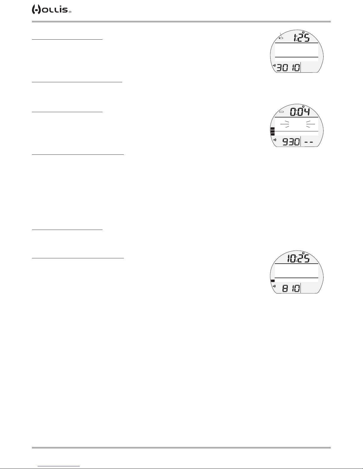
TX1 HE LOW BATTERY WHILE ON THE SURFACE
≤ 2.75 volts (warning level)
• Backlight is completely disabled.
• Battery icon (shell with inner bar) appears solid.
• If a dive is started, the icon is not displayed on the dive mode screens.
• All functions, including Compass Mode, continue to be available.
≤2.50 volts (Too Low - alarm level)
• Battery icon (shell only) will ash for 5 seconds then the unit shuts off completely.
TX1 HE LOW BATTERY DURING A DIVE
≤ 2.75 volts (warning level)
• Backlight is completely disabled.
• All other functions continue to be available.
• Battery icon is not displayed on the dive mode screens.
• Battery icon (shell with inner bar) appears solid upon entry into Surface Mode.
≤ 2.50 volts (Too Low - alarm level)
• Backlight is completely disabled.
• All other functions continue to be available during the dive.
• Battery icon is not displayed on the dive mode screens.
• Upon surfacing, the Battery icon (shell only) and graphic CHANGE BATTERY ash
for 10 minutes, then the unit shuts off completely.
if Low Batt
NORM
NX 32
PO2
BAR
PSI
Low Battery
Warning
CHANGE
BATTERY
NX 36
TLBG
BAR
PSI
Low Battery
(after surfacing)
FTM
SURF
DIVE 0
GAS4
GTR
TAT
min
SURF
GAS5
GTR
TAT
min
TMT(TRANSMITTER) LOW BATTERY
Indication is provided only while on the surface.
≤ 2.75 volts (warning level)
• The graphics TMT# LOW BATTERY appear solid on the Battery Status screen.
• DC functions continue to be available (surface and dive).
≤ 2.50 volts (Too Low - alarm level)
• The graphics TMTx LOW BATTERY alternate with the graphics NORM (or GAUGE)
and DIVE xx on the SURF Main screen.
• The graphics TMTx BATTERY and LOW also ash on the Battery Status screen.
• TMT operation continues until Tank Pressure decreases to 50 PSI.
TLBG
(PZ+)
CF
TMT 1
LOW BATTERY
TX 15/45
PO2
BAR
PSI
TMT Low Battery
(Alarm)
FTM
SURF
GAS3
GTR
TAT
min
OPERATING MODES
NORM Mode >> for Air, Nitrox, and Trimix SCUBA activity with up to 6 Gases/6 TMTs.
GAUGE Mode >> for SCUBA activity with up to 6 TMTs.
If no previous dive has been taken within the past 24 hours, NORM is the default mode upon activation with others accessed as described later.
At any time while operating in Surface Modes, operation will enter the Dive Mode selected upon descent to 5 FT
(1.5 M) for 5 seconds.
• When Wet Activation is set Off, Dive Mode will only be activated when the unit is rst activated and operating in
a surface mode.
• When Wet Activation is set On, the selected Dive Mode will activate upon descent regardless of whether is acti-
vated and operating rst.
© 2002 DESIGN (2014)
15
Doc. 12-4101-r06 (1/21/14)
Page 16

TX1 He OPERATING MANUAL
TRANSITION PERIOD, upon surfacing:
Operation shifts from Dive Mode to Surface Mode upon ascent to 2 FT (0.6 M) for 1 second; however, Surface
mode 'screens' will not be available until a Transition time elapses.
The reason for this is that making a descent during the rst 10 minutes after surfacing from a NORM or GAUGE
dive, is a continuation of that dive.
A descent made after the 10 minute (or 1 minute) interval has elapsed is then considered a new dive.
During the rst 10 minutes after surfacing from a NORM or GAUGE dive, the Dive Main screen will be displayed
with Surface Interval time replacing Current Depth. Dive ALT's can be accessed to view other information pertaining to that dive.
POWER SAVER MODE (PSM)
Once 10 minutes elapse, after the 10 minute (NORM or GAUGE) Transition Period on the surface after a dive,
the unit will enter a Power Saver Mode (PSM) which turns the display screen off until a button is pressed at which
time it will turn back on.
During the 10 minutes that the screen is off, all operations continue as normal in the background with current
updated information displayed as soon as the screen comes on again.
© 2002 DESIGN (2014)
16
Doc. 12-4101-r06 (1/21/14)
Page 17

TX1 He OPERATING MANUAL
NORM
SURFACE MODES
© 2002 DESIGN (2014)
17
Doc. 12-4101-r06 (1/21/14)
Page 18
TX1 He OPERATING MANUAL
TAP
TAP
TAP
TAP
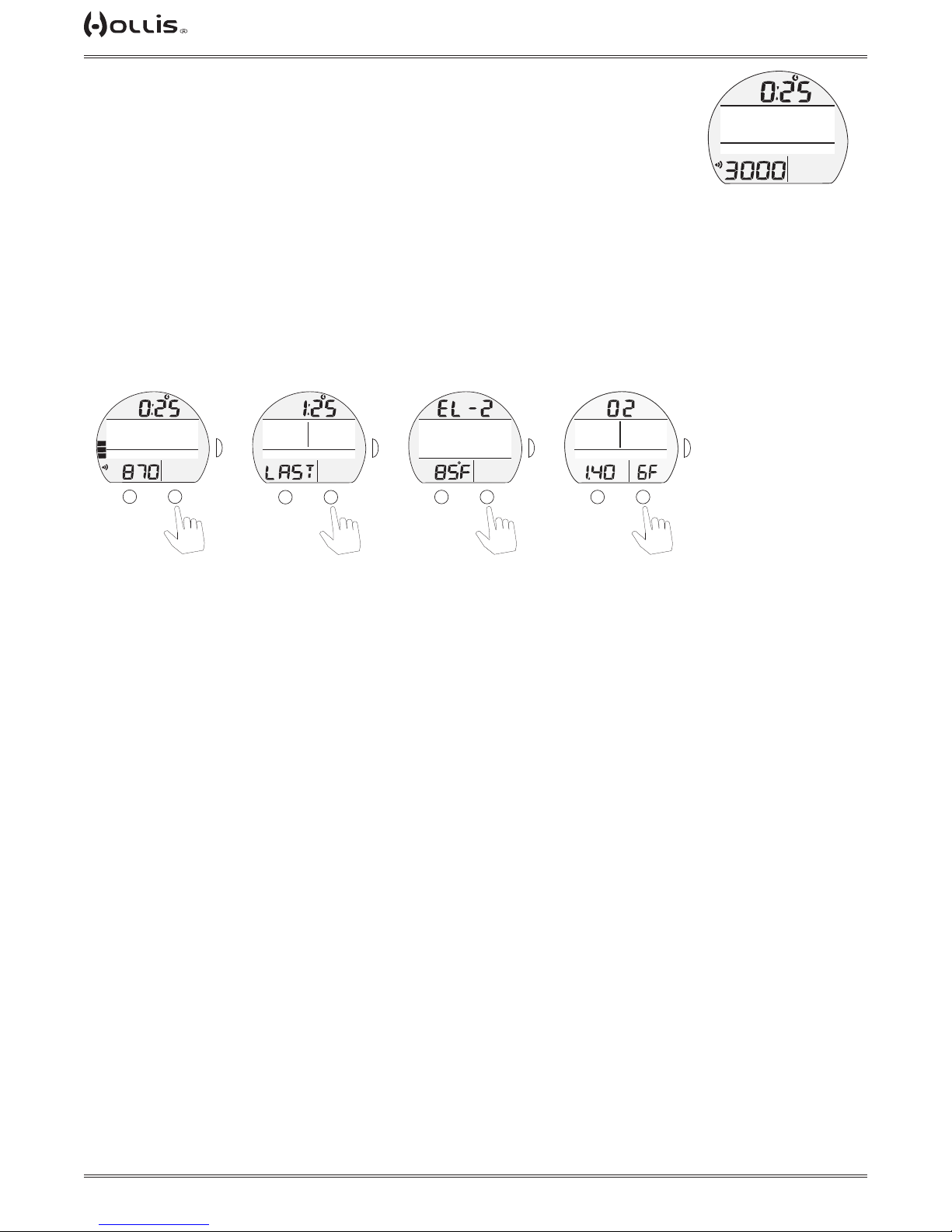
NORM SURF MAIN, information includes:
> SI (hr:min) with Time (clock) and SURF icons; if no dive yet, this is time since activation.
> Graphic NORM (operating mode).
> Graphic DIVE and number of dives completed during that operating period, up to
24 (0 if no dive made yet).
> Tank Pressure (or letters SPG if no TMT) with PSI (or BAR) and Link (speaker)
icons, if the Receiver is successfully Linked with an active TMT (Transmitter), 00
ashing after 15 seconds of lost Link.
> Graphic Gas Name: (AIR, NX (FO2) or TX (FO2)/FHe)) and GAS# of the actual
gas.
> TLBG with icon, if any nitrogen after NORM dives.
NORM SURF ALT SCREENS
Norm Surf Main
(nitrox, dives 2)
NORM
NX 32
TLBG
PO2
BAR
PSI
M
FTM
SURF
DIVE 2
GAS4
GTR
TAT
min
A
S
FT MAX
TLBG
Norm Surf
Alt 1
(PZ+)
EDT
83
232
PO2
BAR
PSI
M
Norm Surf
Alt 2
(PZ+)
FTM
SURF
S
GTR
TAT
min
A
CF
12:45
TLBG
PO2
M
FTM
A
BAR
PSI
S
GTR
TAT
min
A
Norm Surf
(PZ+)
(PZ+)
CF
CF
O2 SAT
43
45%
NX 32
TX 25/35
TLBG
PO2
PO2
BAR
M
Alt 3
GF
%O2 SAT
PSI
58
GAS3
GAS5
A
FTM
SURF
PO2
BAR
PSI
DIVE 0
GAS1
GTR
TAT
min
NORM
aır
NORM SURF MAIN
(no dive yet, set for air)
FTM
FTM
SURF
SURF
S
GTR
TAT
min
NORM SURF ALT 1, information includes:
> SI* (hr:min) with Time (clock) and SURF icons.
> Max Depth* with FT (or M) and MAX icons.
> Elapsed Dive Time* (hr:min) with graphic EDT.
> Graphic LAST, indicating that data is from the dive previously conducted while in
NORM mode.
*Dashes if no previous dive.
NORM SURF ALT 2, information includes:
> Altitude graphic, if EL2 (to EL7), blank if Sea level.
> Time of Day (hr:min) with graphic A (or P).
> Temperature with ° icon and graphic F (or C).
NORM SURF ALT 3, information includes:
> Screen titles O2 and GF.
> Current GF value is displayed.
> O2 % accumulation (current) with graphic O2 SAT.
> PO2 MAX (for active gas) set by the user.
> Graphics GAS # and Gas Name: AIR, NX (FO2) or TX (FO2/FHe), for the actual
gas.
back to main
© 2002 DESIGN (2014)
18
Doc. 12-4101-r06 (1/21/14)
Page 19
TX1 He OPERATING MANUAL
TAP
TAP
TAP
TAP
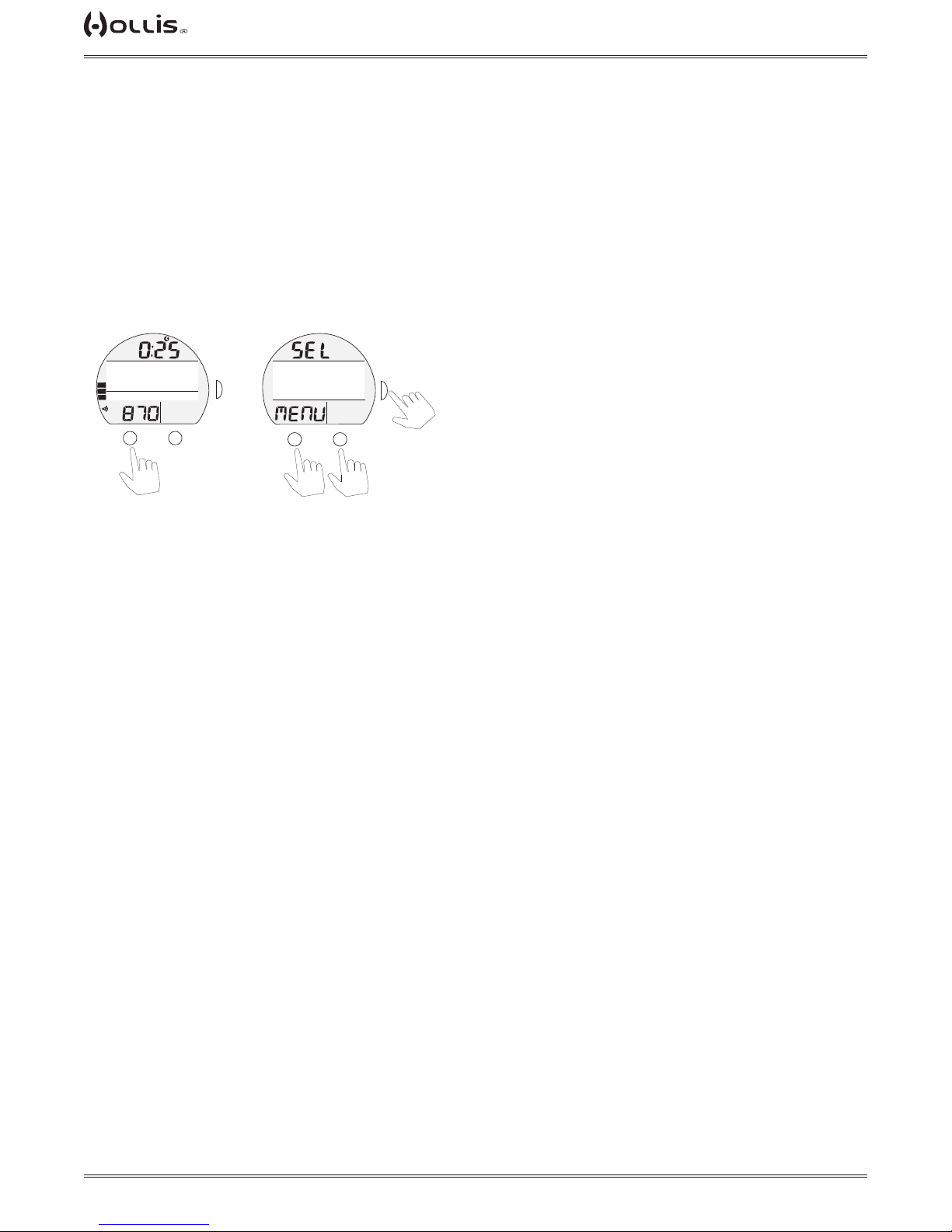
NORM MENU
Selections include:
> GAS MENU.
> FLY/DESAT.
> PLAN.
> LOG.
> SET MENU.
> OP MODE.
> HISTORY
> TX1 ID.
> BATT/TMT
> DIVE PREVIEW
Norm Surf Main
(nitrox 32, dives 2)
FTM
SURF
PO2
M
BAR
PSI
DIVE 2
GAS4
GTR
TAT
min
A
S
NORM
NX 32
TLBG
GAS MENU
The Gas Menu selection provides access to a listing of sub menus that contain items
specic to the selection and use of gases and tranmsitters.
Surf Main Sel Menu
(PZ+)
CF
>GAS MENU
FLY/DESAT
PLAN
LOG
TLBG
PO2
BAR
PSI
or
M
to scroll cursor (>)
FTM
SURF
>
S
GTR
TAT
min
A
to select
downup
Gas Menu, information includes:
> Graphics Gas and MENU with selections -
> GAS SWITCH.
> SELECT GASES.
> SET GASES.
> SET TMT.
These gas sub menus are described after the Main Menu items (starting on page 24)
FLY/DESAT
FLY Time is a count down timer that begins counting down 10 minutes after surfacing
from a dive from 23:50 to 0:00 (hr:min).
DESAT Time, also a count down timer, provides calculated time for tissue desaturation at sea level taking into consideration the algorithm and gradient factor setting.
DESAT Time also begins counting down 10 minutes after surfacing from a dive,
counting down from 23:50 (max) to 0:00 (hr:min).
When the DESAT time reaches 0:00, which will generally occur prior to the FLY count
down reaching 0:00, it will remain on the display until the FLY count down reaches
0:00.
> DESAT is not displayed after a Gauge or Violation dive.
> Desaturation requiring Times greater than 24 hours will display > 24 HR DESAT.
> In the event that Time to Desaturate still remains at the end of 24 hours, the unit is
to turn off. Addtionally, any inert gas and O2 calculations are to clear.
> When other screens are accessed, the FLY and DESAT countdowns continue in
the background.
© 2002 DESIGN (2014)
19
Doc. 12-4101-r06 (1/21/14)
Page 20
TX1 He OPERATING MANUAL
TAP
TAP
TAP
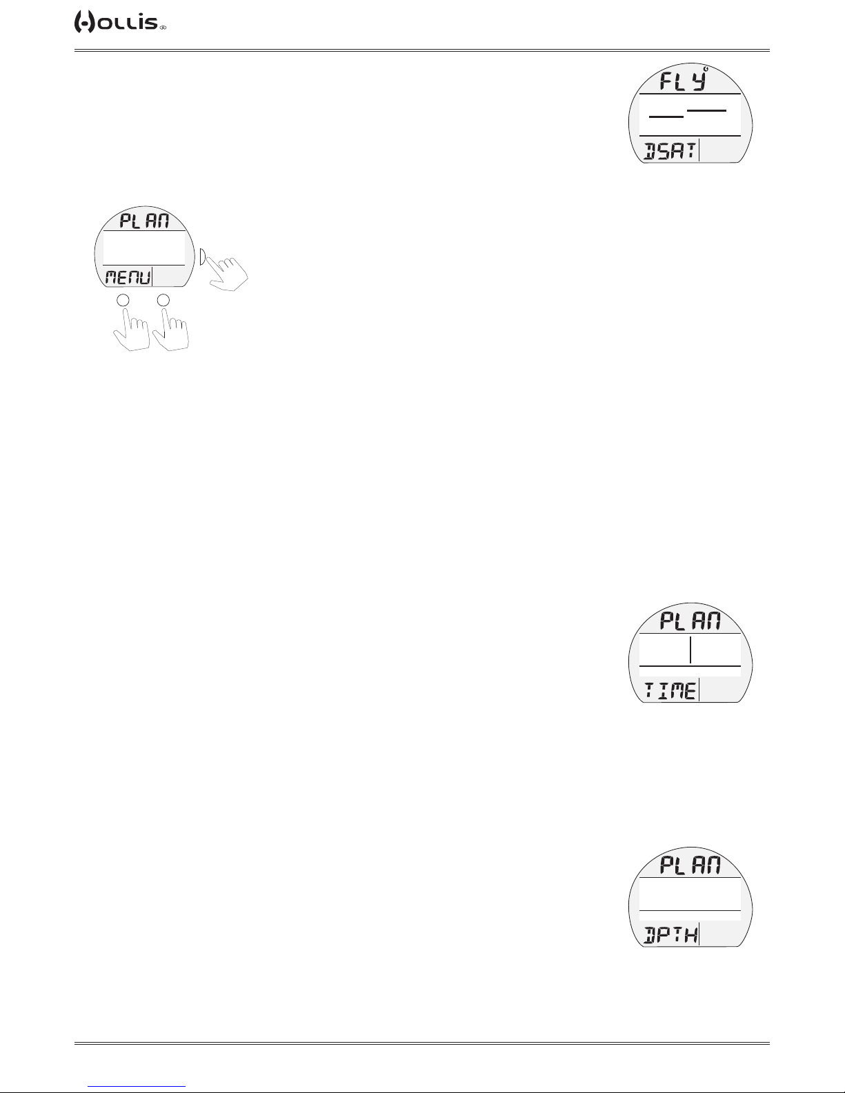
Fly/Desat, information includes:
> Graphics FLY and DSAT with countdown times (hr:min) and Time (clock) icon,
dashes if no dive yet.
PLAN MENU
Selections include:
> Time Limits.
> Depth Limits.
(PZ+)
FTM
CF
>TIME LIMITS
DEPTH LIMITS
TLBG
PO2
M
SURF
BAR
PSI
or
S
GTR
TAT
min
A
to select
downup
to scroll cursor (>)
Time Limits
No Deco Time Limits (NDLs) and O2 Time Limits (OTLs) in Plan Mode are based on
the Algorithm with gradients, the FO2 set for the actual gas, FHe set for the actual
gas, and residual inert gas (or O2) remaining from previous NORM dives. FO2 and
FHe set for other Gases are not used for Plan calculations.
CF
TLBG
(PZ+)
23:50
9:59
PO2
BAR
PSI
FLY/DESAT
FTM
SURF
GTR
TAT
min
Time Limit screens will sequence through Depths from 30 to 190 FT (9 to 57 M),
or the Max Depth that will allow theoretical No Deco Dive Time or OTL of at least 1
minute based upon the previous dive proles in a series of repetitive dives and taking
into account descent and ascent rates of 60 FPM (18 MPM). Depths where the PO2
of the actual gas is > 1.6 shall not be listed.
Time Limits Screen, information includes:
> Plan Depth value with FT (or M) icon - from 30 to 190 FT (9 to 57
M) in increments of 10 FT (3 M).
> Max Depth allowed with FT (or M) and MAX.
> Graphic NDC (or OTL) with Dive Time allowed (min).
> Graphics GAS NAME and GAS# for the actual gas.
> Depth from 30 to 190 FT (9 to 57 M) in increments of 10 FT (3 M).
Depth Limits
The Depth Limits Screen will help determine what the Maximum Operating Depth
(MOD) of the selected gas is. If the actual gas is trimix and the corresponding alarms
are turned on (END Alarm, WOB alarm, and HT alarm), this screen will tell you what
the depth limits are - in relation to those settings.
Depth Limits, information includes:
> Graphic PLAN.
> MOD* (Maximum Operating Depth) - determined by PO₂ settings.
> END** - depth limit where current gas is equal to the set Equivalent Nitrogen Depth
(set in Alarms Menu).
> WOB** - depth limit where current gas is equal to the set Work Of Breathing (set in
Alarms Menu).
> HT (Hypoxic Threshold)** - depth where the PO2 of the gas equals 0.21 ATA.
> Active gas mix.
> Graphics GAS NAME and GAS# for the actual gas
> Graphic DPTH.
NOTE: If any value is greater than 400 ft (120 m), 400 ft (or 120 m) shall be
displayed. Zero shall be displayed if any calculated value is negative.
© 2002 DESIGN (2014)
20
(PZ+)
FTM
CF
FT MAX
90
TX 18/45
TLBG
PO2
BAR
SURF
NDC
15
GAS3
PSI
TIME LIMITS
* Item applies only for AIR or NX.
** No value shown if that alarm is set
to off.
(PZ+)
FTM
CF
MOD END WOB HT
180 130 97 14
FEET
TX 15/45
TLBG
PO2
BAR
DEPTH LIMITS
Doc. 12-4101-r06 (1/21/14)
SURF
GAS5
PSI
GTR
TAT
min
GTR
TAT
min
Page 21
TX1 He OPERATING MANUAL
TAP
TAP
TAP
TAP
TAP
TAP
TAP
TAP
NORM/GAUGE LOG
Information from the latest 24 NORM and/or GAUGE dives is stored for viewing. After
exceeding 24 dives, the most recent dive is stored while the oldest is deleted.
> Dives are numbered from 1 to 24 starting each time NORM (or GAUGE) Dive Mode
is activated. After 24 hours elapse with no dive, the rst dive of the next period of
operation is #1.
> 10 minutes after a dive, the Log screens for all dives stored can be viewed.
If a dive's elapsed time (EDT) exceeds 999 (min), data at the 999 interval is recorded
in the Log upon surfacing of the unit.
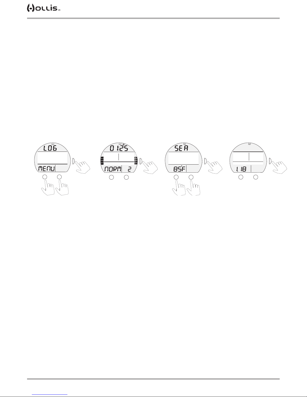
Log Menu, information includes:
> Graphics LOG and MENU with mode (book) icon.
> Listing* of dives displaying - - Number (1 to 24), Date, and start Time; or graphics
NO DIVES YET if a new unit.
*Up and Down arrows are not displayed at the right due to space limitations.
Log Menu
(PZ+)
FTM
CF
> 1 10.23.09 1:35P
2 10.23.09 9:40A
13 9.16.09 10:28A
24 9.4.09 7:58A
TLBG
PO2
M
SURF
BAR
PSI
or
S
GTR
TAT
min
A
to select
downup
to scroll cursor (>)
TLBG
(PZ+)
FT MAX
285
NX 80
PO2
BAR
M
Log Data 1
FTM
SURF
EDT
56
GAS6
PSI
GTR
TAT
min
A
(# of Data 2 screens = # of TMT used*)
Log Data 2
(PZ+)
TMT1
PSI START
BAR
PSI
FTM
S
GTR
TAT
min
A
next
TMT
CF
S
VARI
3000
200 PSI END
TLBG
PO2
M
previous
TMT
CF
O2 SAT
45%
NX 80
TLBG
PO2
(PZ+)
BAR
M
Log Data 3
SURF
GF MAX
58
GAS6
PSI
GTR
TAT
min
A
S
back to
Log Menu
or
to Log Data 4
*If no TMTS were active, Log Data 2 screen displays ALL TMTS OFF.
Log Data 1, information includes:
> Log (book) icon.
> Pre dive Surface Interval (hr:min) with Time (clock) and SURF icons, - : - - if # 1 (no
previous dive that period).
> Max Depth with graphics FT (or M) and MAX.
> Elapsed Dive Time (min) with graphic EDT.
> Graphic NORM, GAUG, or VIOL with dive Number.
> TLBG with max segment ashing, others xed up to end of dive accumulation. All
ash if Violation. Blank if GAUG.
> VARI, max Ascent Rate sustained for 4 sec.
> Graphics GAS NAME and GAS# (gas used at the end of dive).
Log Data 2, information includes:
> Log (book) icon.
> Graphic SEA (or EL2 - EL7), altitude level of dive.
> Graphics TMT#, xxx PSI (or BAR) START, and xxx PSI (or BAR) END, indicating
Tank pressures.
> Graphics ALL TMTS OFF if no TMTS were active during the dive.
> Temperature with ° icon and graphic F (or C), minimum recorded during that dive.
© 2002 DESIGN (2014)
21
Doc. 12-4101-r06 (1/21/14)
Page 22
TX1 He OPERATING MANUAL
TAP
TAP
TAP
Log Data 3, (mix gas dive only), information includes:
> Log (book icon).
> O2 at the end of the dive (2 dashes if VGM or MOD exceeded), with graphic % O2
SAT.
>Highest GF during the dive (2 dashed if VGM), with graphic GF MAX
> Max level of PO2 achieved with icon.
> Graphics GAS NAME and GAS# (gas used at the end of dive).
SET MENU
The Set Menu selection provides access to a listing of sub menus that contain items
specic to NORM and GAUGE modes.
Set Menu, information includes:
> Graphics SEt and MENU with selections -
> A - ALARMS.
> U - UTILITIES.
> T - TIME.
> S - SHORTCUT.
> D - DIVE MAIN.
> P - PREVIEW.
These Set Groups are described after the Main Menu items (starting on page 28).
OP (OPERATING) MODE
This feature allows another Operating Mode to be selected.
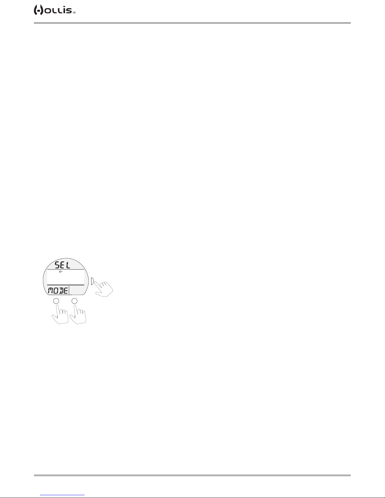
Select OP Mode, information includes:
> Graphics SEL and MODE.
> Graphic NORM, ashing.
> Graphics GAUGE.
(PZ+)
FTM
CF
>NORM
GAUGE
TLBG
PO2
M
to scroll cursor (>)
SURF
BAR
PSI
or
S
GTR
TAT
min
A
to select
downup
© 2002 DESIGN (2014)
22
Doc. 12-4101-r06 (1/21/14)
Page 23
TX1 He OPERATING MANUAL
TAP
TAP
HISTORY (NORM/GUAGE)
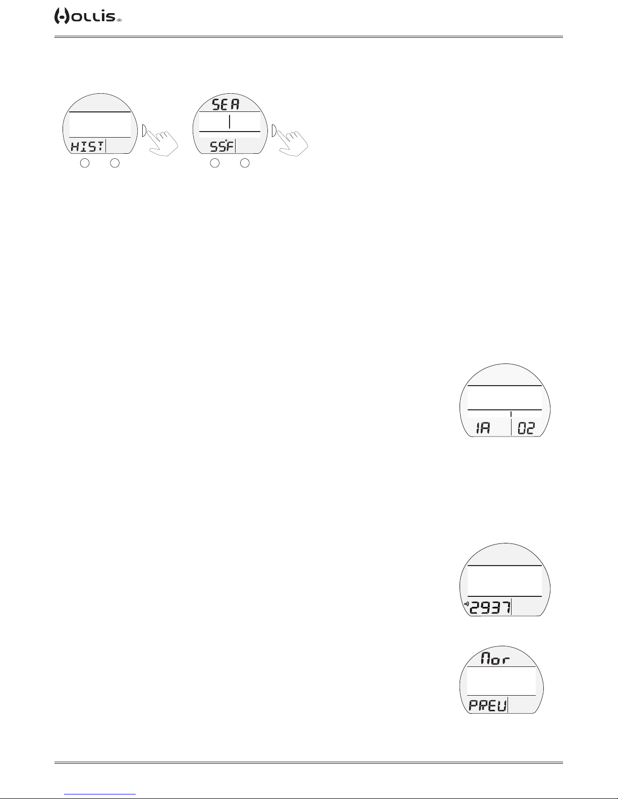
History is a summary of data recorded during all NORM and GAUGE dives conducted.
History 1 History 2
(PZ+)
FTM
CF
TOTAL
68 DIVES
57 HOURS
TLBG
PO2
M
SURF
BAR
PSI
S
GTR
TAT
min
A
CF
FT MAX
TLBG
(PZ+)
EDT
89
232
PO2
BAR
PSI
M
FTM
S
GTR
TAT
min
A
back to
Main Menu
History 1, information includes:
> Graphic TOTAL, or NO DIVES YET (if new unit).
> Total dives recorded (up to 9999) with graphic DIVES.
> Total dive hours recorded (up to 9999) with graphic HOURS.
> Graphic HIST.
History 2, information includes:
> Graphic SEA (or EL2 to EL7), highest Altitude at which a dive was conducted.
> Max Depth recorded with FT (or M) and MAX icons.
> Longest dive time (minutes) recorded during a single dive (up to 999 min) with
graphic EDT.
> Lowest Temperature recorded during a dive with icon and graphic F (or C).
TX1 ID
This information should be recorded and kept, it will be required in the event that your
unit requires factory service.
ID (Identication), information includes:
> Graphic TX1 He ID.
> Graphic SN with the factory programmed serial number.
> Graphic FIRMWARE with 1A (or higher)*, indicating the Firmware revision level currently installed in the unit.
> Graphic LCD with 01 (or higher), indicating the Display's revision number.
CF
FTM
TX1 ID
SN 123456
FIRMWARE LCD
TLBG
PO2
BAR
PSI
TX1 ID
GTR
TAT
min
*This number will change if the Firmware is updated by factory service or by future download
of revised rmware from the Hollis web site.
BATT/TMT
Access to this selection activates the TX1 He's Receiver, then starts a transmitter search. The battery status of the TX1 He wrist unit and all transmitters can be
viewed from the same BATT/TMT Status screen. Refer to pages 24 and 33 for more
information.
DIVE PREVIEW
This feature provides quick access to a screen that displays up to 4 settings that can
be pre selected* using the Set P Menu.
Preview, information includes:
> Graphics Nor and PREV.
> Selections* with Set Points entered using that menu.
*If no selections have been made yet, the graphics USE SET P TO SELECT ENTRIES will be
displayed.
© 2002 DESIGN (2014)
23
FTM
CF
TX1 BATT GOOD
>TMT1 BATT GOOD
TMT2 BATT LOW
TMT3 NOT AVAIL
TLBG
PO2
BAR
SURF
>
PSI
GTR
TAT
min
BATT/TMT STATUS
(PZ+)
FTM
CF
GAS1
DEPTH AL
SS
LAST STOP
TLBG
PO2
BAR
SURF
TX 10/40
150 FT
0N
10 FT
PSI
GTR
TAT
min
PREVIEW
Doc. 12-4101-r06 (1/21/14)
Page 24
TX1 He OPERATING MANUAL
TAP
TAP
TAP
TAP
TAP
TAP
GAS SUB MENUS
Information that follows describes the sub menus (GAS SWITCH, SELECT GASES,
SET GASES, SET TMT) that are accessed from the Gas Menu.
Overview
> It is not possible to Switch Gas to a gas that has a PO2 < 0.17 at the current depth.
Gas Switch Menu
(PZ+)
FTM
CF
>GAS1 AIR
GAS2 O2
GAS3 TX 15/45
GAS4 NX 32
TLBG
PO2
M
SURF
S
BAR
>
PSI
GTR
TAT
min
or
A
to select
downup
to scroll cursor (>)
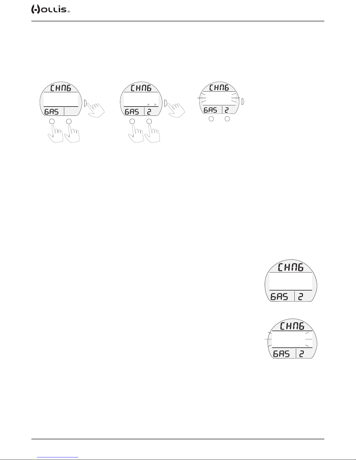
Gas Switch Menu, information includes:
> Graphic CHNG and GAS.
> Graphic Selections GAS # and GAS NAMES
Gas Switch Screen
(gas 2 selected)
(PZ+)
FTM
CF
MOD END WOB HT
317 230 215 13
FEET
>CONFIRM YES
TLBG
PO2
M
SURF
BAR
PSI
or
S
GTR
TAT
min
A
to conrm
to toggle YES/NO
TMT Search Screen
(PZ+)
FTM
TMT 2
BAR
PSI
SURF
GTR
TAT
min
A
CF
SEARCHING FOR -
TLBG
PO2
M
S
NOTE: Only the available gases (selected in Select Gases Menu) are displayed. If only one gas is selected in the Select Gases Menu, this menu will
not be available.
Gas Switch Screen, information includes:
> Graphic CHNG, GAS, and selected gas number 1 - 6.
> MOD.
> END*.
> WOB*.
> HT**.
> Graphic CONFIRM with selections YES or NO.
* These only display if switching to a trimix gas, and their respective alarms are set on.
** HT only displays if switching to a trimix gas.
TMT (Transmiter) Search Screen
> Only displays if the transmitter is switched to on, see Set TMT section.
> Graphic CHNG, GAS, and selected gas number 1 - 6.
> Graphic message SEARCHING FOR - TMT, ashing for 10 seconds.
> Graphic message TMT (1 - 6) NOT AVAILABLE if the transmitter signal is not established within 10 seconds.
PO2 < 0.17 ATA Hypoxic Gas Warning (Mandatory Decline)
Attempting to switch to a gas with a PO2 < 0.17 ATA results in the TX1 He displaying the Hypoxic Gas Decline screen. This message must be aknowledged with the
S button. After which, the Gas Switch Menu will display. Then another gas may be
selected from the menu.
(PZ+)
FTM
CF
SURF
TMT 2
NOT AVAILABLE
TLBG
PO2
BAR
PSI
TMT SEARCH
(unable to link)
(PZ+)
FTM
CF
PO2<0.17
CANNOT SWITCH
TO HYPOXIC GAS
>DECLINE
TLBG
PO2
BAR
HYPOXIC GAS WARNING
(mandatory decline)
SURF
PSI
GTR
TAT
min
© 2002 DESIGN (2014)
24
Doc. 12-4101-r06 (1/21/14)
Page 25
TX1 He OPERATING MANUAL
TAP
TAP
TAP
TAP
TAP
TAP
TAP
TAP
TAP
0.17 ≤ PO2 ≤ 0.21 ATA Hypoxic Gas Warning (Low PO2)
Switching to a 0.17≤ PO2 ≤ 0.21 ATA gas will result in a warning screen. The diver may choose to proceed or not
with the gas switch by conrming yes or no.
(PZ+)
FTM
CF
!WARNING!
HYPOXIC GAS
>CONFIRM YES
TLBG
PO2
M
to toggle YES/NO
High PO2 Warning
Switching to a gas with a PO2 > 1.6 ATA, while underwater, will result in a warning screen. The diver may choose
to proceed or not with the gas switch by conrming yes or no.
CF
!WARNING!
!WARNING!
PO2>1.6
PO2 > 1.6 ATA
FT
>CONFIRM YES
>CONFIRM YES
TLBG
TLBG
PO2
PO2
M
SURF
BAR
PSI
or
(PZ+)
BAR
BAR
PSI
PSI
or
S
GTR
TAT
min
A
SURF
A
to select
FTM
FTM
S
VARI
GTR
GTR
TAT
TAT
min
min
to select
to toggle YES/NO
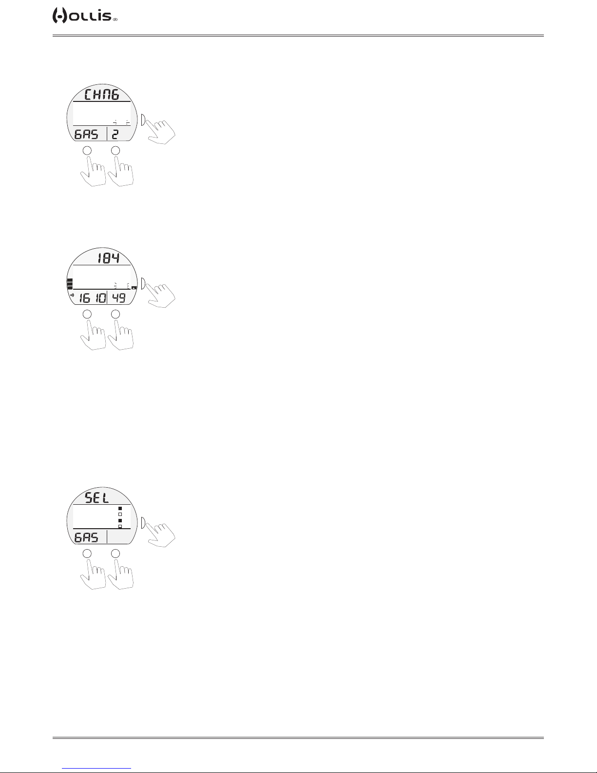
Select Gases Menu
Six possible gases may be made available for switching by selecting or deselecting them in this menu.
Information includes:
> Graphic SEL and GAS.
> Graphic selections Gas# and GAS NAMES
> Filled boxes for available gases.
> Empty boxes for unavailable gases.
(PZ+)
FTM
CF
>GAS1 AIR
GAS2 O2
GAS3 TX 15/45
GAS4 NX 32
TLBG
PO2
M
to scroll cursor (>)
The current active gas cannot be deselected without switching to another gas in the Gas Switch Menu rst.
SURF
S
BAR
>
PSI
GTR
TAT
min
or
A
to select
downup
© 2002 DESIGN (2014)
25
Doc. 12-4101-r06 (1/21/14)
Page 26
TX1 He OPERATING MANUAL
TAP
TAP
TAP
TAP
TAP
TAP
TAP
TAP
TAP
TAP
TAP
TAP
Set Gases
This feature provides for the programming of the gas mixtures.
Set Gases Menu
(PZ+)
FTM
CF
>GAS1 AIR
GAS2 TX 18/45
GAS3 NX 36
GAS4 NX 50
TLBG
PO2
M
SURF
S
BAR
>
PSI
GTR
TAT
min
or
A
to select
downup
to scroll cursor (>)
Gas Conrmation
(conrming gas 4)
(PZ+)
FTM
CF
MOD END WOB HT
317 160 155 13
FEET
>CONFIRM YES
TLBG
PO2
M
SURF
BAR
PSI
or
S
GTR
TAT
min
A
to select
Gas Set Screen
(setting gas 1)
(PZ+)
FTM
CF
>PO2 MAX 1.4
FO2 21
FHE 0
TLBG
PO2
M
SURF
BAR
PSI
or
S
GTR
TAT
min
A
to select
downup
to scroll cursor (>)
Set Gas Screen
(active set point ashing)
(PZ+)
(PZ+)
FTM
FTM
SURF
CF
CF
>PO2 MAX 1.4
>PO2 MAX 1.4
FO2 21
FO2 21
FHE 0
FHE 0
TLBG
TLBG
PO2
PO2
M
SURF
BAR
BAR
PSI
PSI
or
S
GTR
GTR
TAT
TAT
min
min
A
to save set point
alternate (+)alternate (-)
to increase or
decrease set point
Set Gas Screen
(PZ+)
FTM
CF
>PO2 MAX 1.4
FO2 21
FHE 0
TLBG
PO2
M
SURF
BAR
PSI
S
GTR
TAT
min
A
HOLD
to save
gas mix
to toggle YES/NO
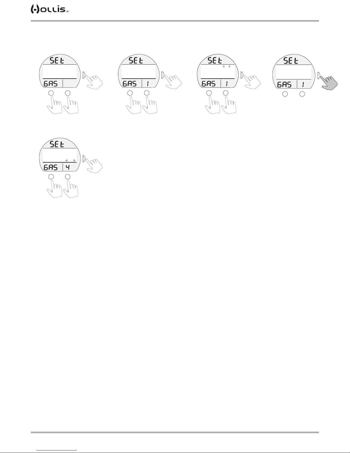
Set Gas Menu, information includes:
> Graphics SET and Gas.
> Graphic selections Gas# and GAS NAMES
Gas Set Screen, information includes:
> Graphics SET and GAS (1 - 6).
> Graphic selections PO2 Max, FO2, FHe.
NOTE: If FHE is set to zero (0) while FO2 < 21, the FO2 shall automatically be reset to 21.
If the user tries to decrease the FO2 below 21 while FHe = 0, a warning screen with the message:
“CANNOT SET FO2 BELOW 21 WHILE FHE = 0” shall be displayed.
Gas Conrmation Screen, information includes:
> Graphic SET and GAS (1 - 6).
> MOD.
> END*.
> WOB*.
> HT**.
> Graphic selection YES or NO.
* These only display if the gas is set to a trimix gas, and their respective alarms are set on.
** HT only displays if switching to a trimix gas.
Transmitters
The TX1 He allows up to 6 transmitters to be utilized to monitor tank pressures. The Set TMT menu allows for the
programming of the wrist unit to receive signals from transmitters. See the Dive Mode Features section (p. 35) for
further information on transmitters.
© 2002 DESIGN (2014)
26
Doc. 12-4101-r06 (1/21/14)
Page 27
TX1 He OPERATING MANUAL
TAP
TAP
TAP
TAP
TAP
TAP
TAP
TAP
TAP
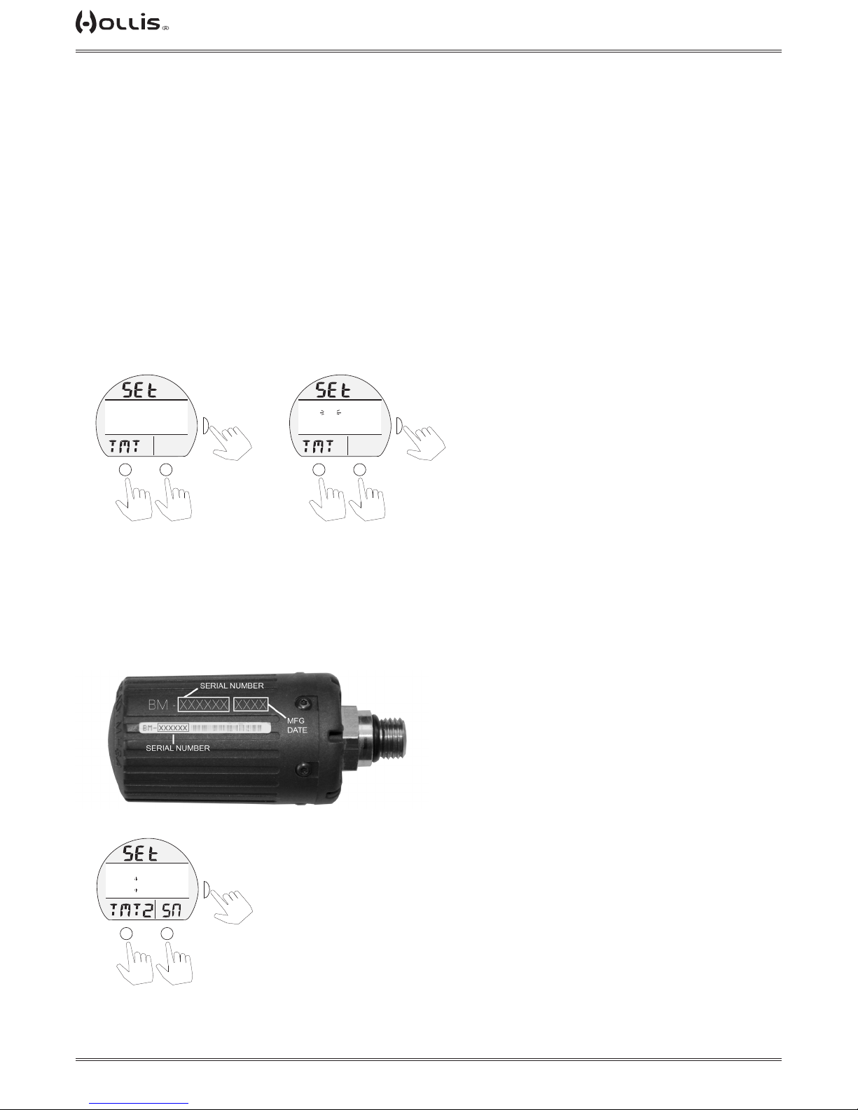
Set TMT (Transmitter) Menu, information includes:
> Graphics SEt and TMT.
The following graphic selections (last Set Points saved):
> TMT 1 - Set Points >> OFF, ON, SET.
> TMT 2 - Set Points >> OFF, ON, SET.
> TMT 3 - Set Points >> OFF, ON, SET.
> TMT 4 - Set Points >> OFF, ON, SET.
> TMT 5 - Set Points >> OFF, ON, SET.
> TMT 6 - Set Points >> OFF, ON, SET.
NOTE: When using multiple transmitters they should be labeled with their assigned number to avoid
confusion.
NOTE: If the TMT is set OFF for the active gas, the letters SPG will be displayed in place of a pressure
reading on the Main Screen.
Set TMT Menu
Set TMT Menu
(TMT2, OFF ashing)
(PZ+)
CF
TMT1 ON
>TMT2 OFF
TMT3 OFF
TMT4 OFF
TLBG
PO2
BAR
PSI
or
A
M
to scroll cursor (>)
FTM
SURF
S
>
GTR
TAT
min
to select
downup
(PZ+)
FTM
CF
TMT1 ON
>TMT2 OFF
TMT3 OFF
TMT4 OFF
TLBG
PO2
M
SURF
BAR
PSI
or
A
to toggle ON/SET/OFF
S
>
GTR
TAT
min
to select
nextprevious
Hold M button to return to Surface Main, or hold S button to return to Gas Menu.
Set Serial Number (Code) Screen, information includes:
> Graphics SEt and TMT 1 (2, 3, 4, 5, 6)
> Graphic LINK CODE with the serial number (6 digits), the 1st (left) digit ashing.
The serial number can be located in two places directly on the transmitter (see below).
Set Serial Number
(active digit ashing)
(PZ+)
FTM
CF
LINK CODE
TLBG
PO2
M
SURF
123456
BAR
PSI
or
A
S
GTR
TAT
min
to save set point
(+) (-)
to increase or
decrease set point
After the sixth digit is saved, the TX1 He will return to the Set TMT Menu.
© 2002 DESIGN (2014)
27
Doc. 12-4101-r06 (1/21/14)
Page 28
TX1 He OPERATING MANUAL
TAP
TAP
TAP
TAP
TAP
TAP
SET GROUPS
Information that follows describes the selections contained in the NORM Set Groups (A, U, T, S, D, P) that are
accessed from the Set Menu.
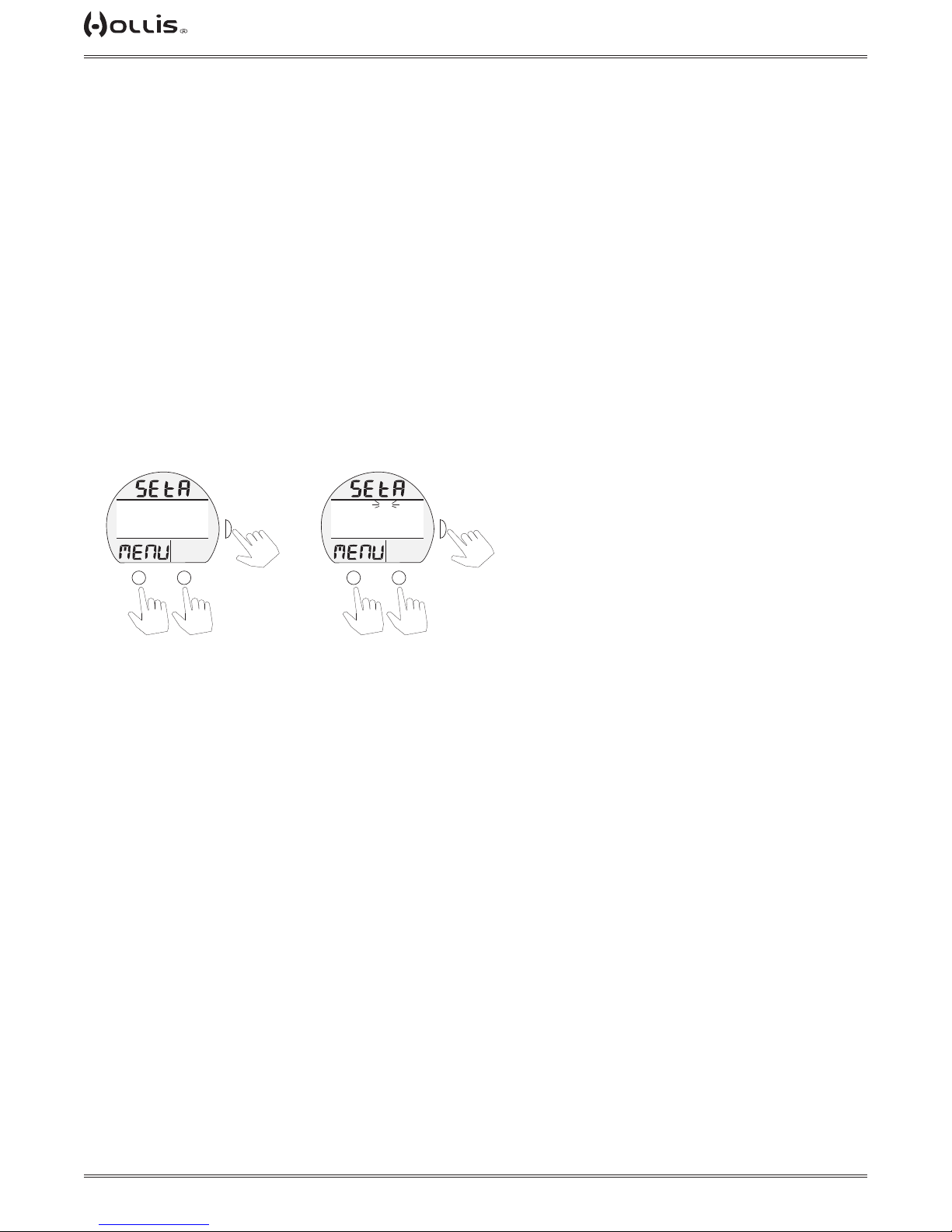
SET A (Alarms) Menu, information includes:
> Graphics SEt A and MENU.
Selections with their last Set Points saved include:
> AUD with Set Point (ON or OFF), audible.
> DEPTH with Set Point (OFF, or 30 to 400 FT, or 10 to 120 M), increments of 10 FT (1 M).
> EDT with Set Point (OFF, or 10 to 180 MIN), elapsed dive time, increments of 5 MIN.
> TLBG* with Set Point (1 to 4 BAR), increments of 1 BAR.
> DTR* with Set Point (OFF, or 1 to 20 MIN), increments of 1 MIN.
> TP with Set Point (OFF, or 300 to 3000 PSI, or 20 to 200 BAR), increments of 250 PSI (5 BAR).
> END* with Set Point (OFF, 100 to 200 FT, or 30 to 60 M), increments of 10 FT (1 M).
> WOB* with Set Point (OFF, 100 to 200 FT, or 30 to 60 M), increments of 10 FT (1 M).
> ICD* with Set Point (OFF, ON).
*These items apply to NORM Mode only.
Set A Menu
(PZ+)
FTM
CF
>AUD
DEPTH
EDT
TLBG
TLBG
PO2
M
SURF
ON
200 FT
60 MIN
4 BAR
BAR
PSI
or
A
to scroll cursor (>)
Set Selection
(active set point ashing)
(PZ+)
FTM
CF
>AUD
DEPTH
>
S
GTR
TAT
min
to select
EDT
TLBG
TLBG
PO2
M
downup
SURF
ON
200 FT
60 MIN
>
4 BAR
BAR
PSI
GTR
TAT
min
or
A
S
to save
next (+) previous (-)
to toggle or increase
set point
© 2002 DESIGN (2014)
28
Doc. 12-4101-r06 (1/21/14)
Page 29
TX1 He OPERATING MANUAL
TAP
TAP
TAP
TAP
TAP
TAP
TAP
TAP
TAP
TAP
TAP
TAP
TAP
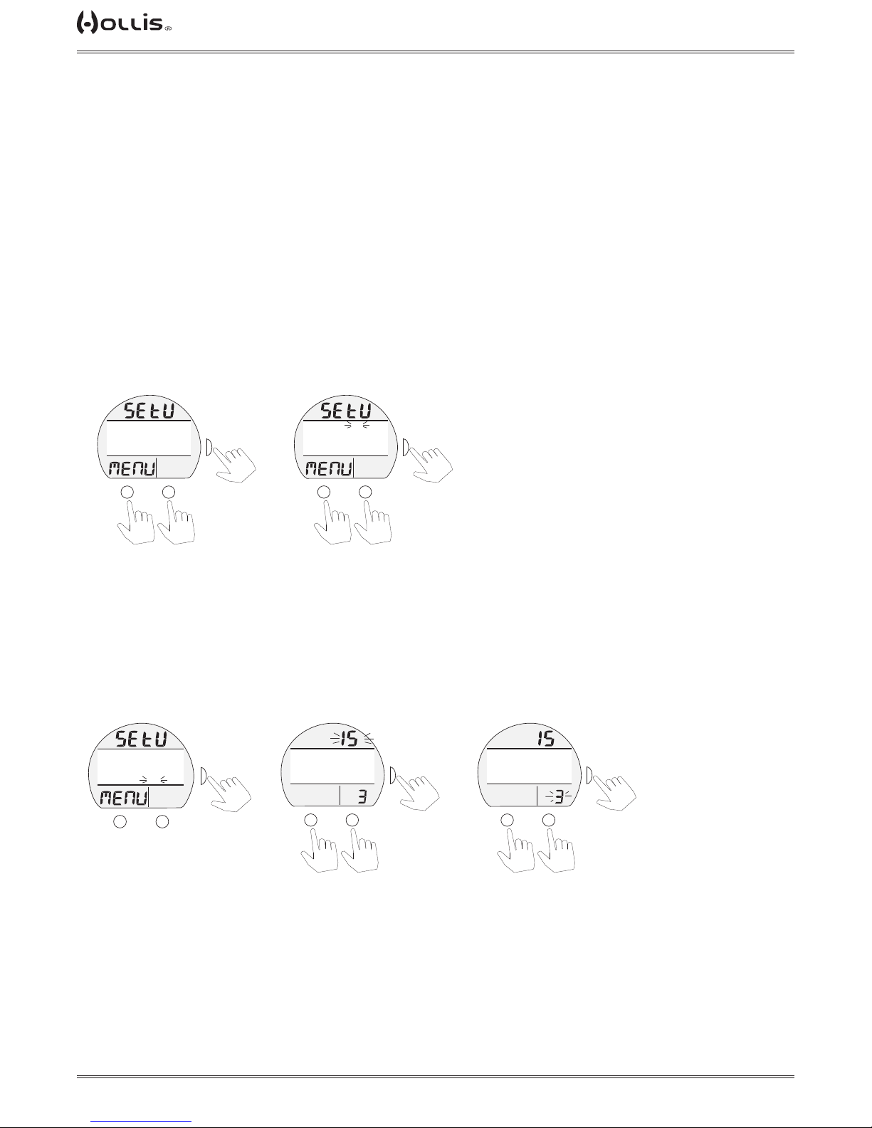
SET U (Utilities) Menu, information includes:
> Graphics SEt U and MENU.
Selections with their last Set Points saved include:
> WET ACT with Set Point (ON or OFF) >> wet activation.
> UNITS with Set Point (IMP or MET) >> imperial or metric.
> DEEP* with Set Point (ON or OFF) >> no deco deep stop.
> SAFE* with Set Point** (OFF, TMR, ON) >> no deco safety stop.
> SET GF* with Set Point** (CONS 1 - 5 or SET CUSTOM GF)
> O2 NARC* with Set Point (YES or NO)
> GLO DUR with Set Point (0, 5, 10, or 15 SEC) >> time backlight remains on.
> SAMPLE with Set Point (2, 15, 30, or 60 SEC) >> rate data is recorded for PC download.
> LAST STOP* with Set Point (10 ft/3m or 20ft/6m)
*These items apply to NORM only.
** Expanded description, following.
Additional information relating to the effects of the items included are described in associated sections throughout this manual.
Set U Menu
(PZ+)
FTM
CF
>WETACT
UNITS
DEEP
SAFE
TLBG
PO2
M
SURF
ON
IMP
OFF
>
ON
BAR
PSI
GTR
TAT
min
or
A
S
to select
Set Selection
(active set point ashing)
(PZ+)
FTM
CF
>WETACT
UNITS
DEEP
SAFE
TLBG
PO2
M
SURF
ON
IMP
OFF
>
ON
BAR
PSI
GTR
TAT
min
A
or
S
to save
downup
to scroll cursor (>)
previous (-)
next (+)
to toggle or increase
set point
Set Safety Stop, information includes:
The Set U menu will display OFF, ON, TMR solid, or SET.
> Select OFF, ON, or TMR: same as above menu
> Select SET (stop depth and time):
Set U Menu
(safe, set ashing)
(PZ+)
FTM
CF
>WETACT
UNITS
DEEP
SAFE
TLBG
PO2
M
SURF
ON
IMP
OFF
>
SET
BAR
PSI
GTR
TAT
min
A
S
TLBG
Set Selected
(depth ashing)
(PZ+)
FTM
CF
WETACT ON
UNITS IMP
DEEP OFF
>SAFE SET
PO2
M
SURF
>
BAR
PSI
or
S
GTR
TAT
min
A
to next
(+) (-)
to toggle set point
(10, 15, 20 ft) or
(3, 4, 5, 6 m)
Set Selected
(time ashing)
(PZ+)
FTM
CF
WETACT ON
UNITS IMP
DEEP OFF
>SAFE SET
TLBG
PO2
M
SURF
>
BAR
PSI
or
S
GTR
TAT
min
A
to save
(+) (-)
to toggle set point
(3 or 5 min)
© 2002 DESIGN (2014)
29
Doc. 12-4101-r06 (1/21/14)
Page 30
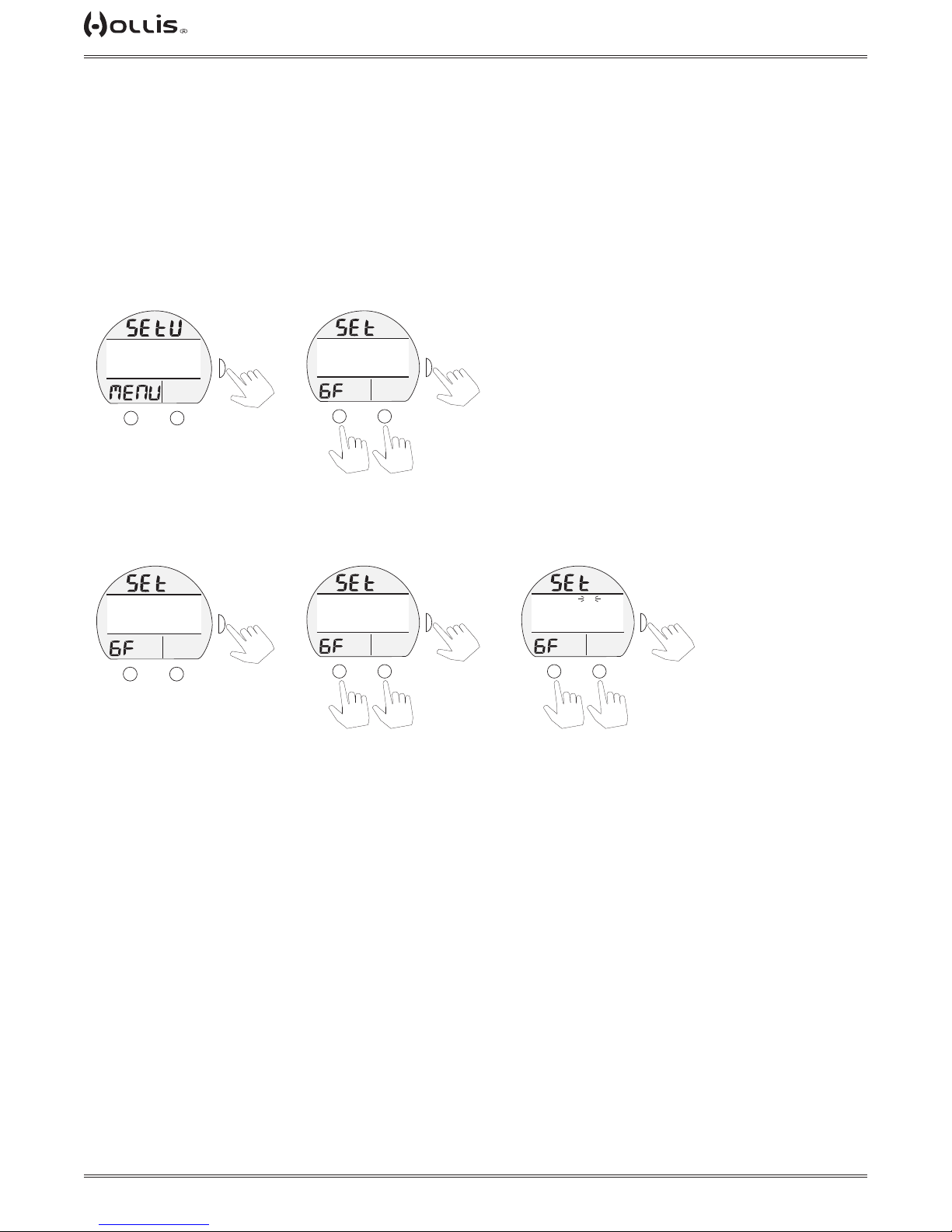
Set GF (Gradient Factor), information includes:
TAP
TAP
TAP
TAP
TAP
TAP
TAP
TAP
TAP
TAP
TAP
> Graphics SET and GF.
Selections with the last Set Point saved include:
> CONS 1 = GF 90 • 90
> CONS 2 = GF 35 • 90
> CONS 3 = GF 30 • 85
> CONS 4 = GF 25 • 80
> CONS 5 = GF 20 • 75
> SET CUST GF
Set U Menu
(set GF, selected)
(PZ+)
FTM
CF
>SET GF
O2 NARC
GLO DUR
SAMPLE
TLBG
PO2
M
SURF
30-80
YES
15 SEC
60 SEC
BAR
PSI
A
>
S
>
GTR
TAT
min
Set GF Menu
(PZ+)
FTM
CF
>CONS 1=GF 90 - 90
CONS 2=GF 35 - 90
CONS 3=GF 30 - 85
CONS 4=GF 25 - 80
TLBG
PO2
M
SURF
BAR
PSI
GTR
TAT
min
or
A
to scroll cursor (>)
TX1 He OPERATING MANUAL
S
>
to select
downup
Selecting a Custom Gradient Factor:
Set GF Menu
(set custom GF, selected)
(PZ+)
FTM
CF
CONS 5=GF 20 - 75
>SET CUSTOM GF
TLBG
PO2
M
SURF
>
BAR
PSI
S
GTR
TAT
min
A
Further information on Gradient Factors can be found in the Dive Mode Features section of this manual.
Custom GF Menu
(PZ+)
FTM
CF
>GF LOW 30
GF HIGH 80
TLBG
PO2
M
SURF
BAR
PSI
GTR
TAT
min
or
A
downup
to scroll cursor (>)
S
to select
GF Low or High Selected
(set point ashing)
(PZ+)
FTM
CF
>GF LOW 30
GF HIGH 80
TLBG
PO2
M
SURF
BAR
PSI
GTR
TAT
min
A
or
(+) (-)
to increase/decrease
set point (10 - 90)
S
to save
© 2002 DESIGN (2014)
30
Doc. 12-4101-r06 (1/21/14)
Page 31
TX1 He OPERATING MANUAL
TAP
TAP
TAP
TAP
TAP
TAP
TAP
TAP
TAP
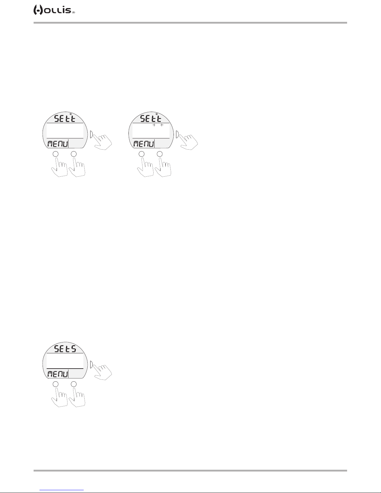
SET T (Time/Date) Menu, information includes:
> Graphics SEt t and MENU with Time (clock) icon.
Selections with their last Set Points saved include:
> DATE FORM with Set Point (M.D or D.M) >> date format, M.D = Month.Day, D.M = Day.Month
> HOUR FORM with Set Point (12 or 24) >> hour format, 12 = 12: A to 11: P, 24 = 0: to 23:
> TIME with Set Point (hr:min) >> 12:01 A to 11:59 P, if 12 Hour Format (or 0:01 to 23:59, if 24 Hour Format).
> DATE with Set Point (M.D.Y or D.M.Y) >> Month.Day.Year or Day.Month.Year, arranged by Date Format set:
Set T Menu
(PZ+)
FTM
BAR
PSI
or
SURF
D.M
12
12:26A
1. 8.12
GTR
TAT
min
A
CF
>DATE FORM
HOUR FORM
TIME
DATE
TLBG
PO2
M
S
to select
TLBG
Set T Menu
(set point ashing)
(PZ+)
FTM
BAR
PSI
or
SURF
D.M
12
12:26A
1. 8.12
GTR
TAT
min
A
S
CF
>DATE FORM
HOUR FORM
TIME
DATE
PO2
M
to save
downup
to scroll cursor (>)
to toggle or increase
next (+) previous (-)
set point
> The left digits of the Time and Date selections will ash rst allowing them to be changed after which the next
digits (to the right) ash allowing them to be changed.
> TIME (hr:min) >> Hour digits ash, then Minutes.
> DATE (m.d.y or d.m.y) >> Year digits ash, then Month, then Day, regardless of their position.
SET S (Shortcut) Menu, information includes:
> Graphics SEt S and MENU.
One item can be selected from the following menu list. That item (referred to as a Shortcut) can then be accessed
directly by pressing M (2 sec) while viewing the Surface Main.
Selections include:
> SELECT GASES.
> SET GASES.
> LOG MENU.
> MY INFO (default Shortcut until another item is selected).
> SET HEADING.
> SET TIME.
Set S Menu
(PZ+)
FTM
CF
>SELECT GASES
SET GASES
LOG MENU
MY INFO
TLBG
PO2
M
SURF
S
BAR
>
PSI
GTR
TAT
min
A
or
to select
downup
to scroll cursor (>)
© 2002 DESIGN (2014)
31
Doc. 12-4101-r06 (1/21/14)
Page 32
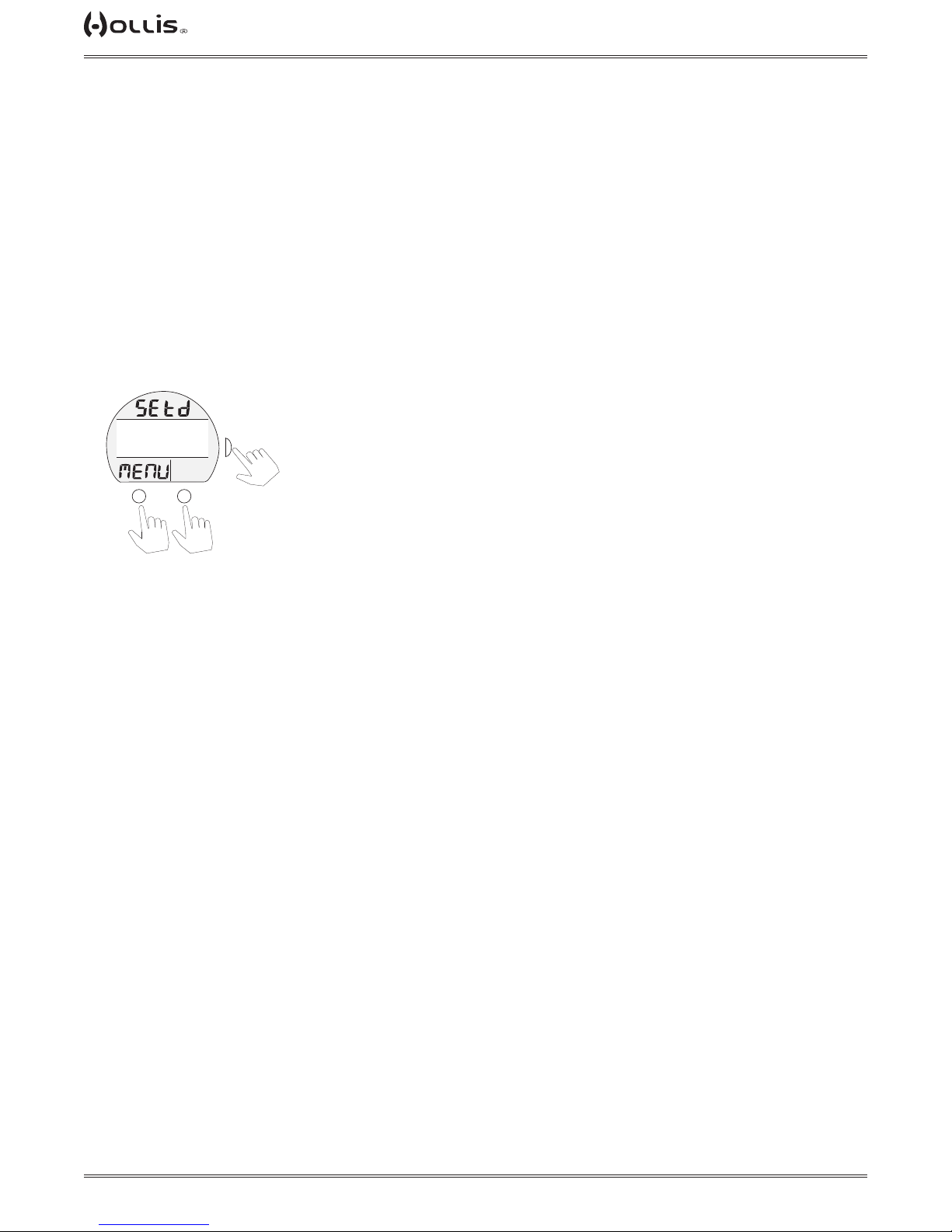
TX1 He OPERATING MANUAL
TAP
TAP
TAP
SET D (Dive Main) Menu, information includes:
> Graphics SEt D and MENU.
The default screen for No Deco dives (except while at Stops) displays Current Depth, NDC time, Pressure, and
GTR (gas time remaining). Items such as Max Depth and EDT (elapsed dive time) are displayed on Alternate
screens. Set D allows certain items to be added to the Main (moving them from the Alternates).
One item can be selected from the following menu list.
> USE DEFAULT >> no change to the display.
> ADD EDT >> adds Elapsed Dive Time also reduces the size of NDC digits.
> ADD MAX D >> adds Max Depth, also reduces the size of NDC digits.
> ADD EDT + MAX D >> displays NDC, EDT, & Max D with smaller digits.
> ADD O2 DATA >> reduces the size of NDC digits & PO2 replaces Pressure (which moves to an Alternate).
> ADD GF>> adds Gradient Factor while reducing the size of NDC digits.
Set D Menu
(PZ+)
FTM
CF
>USE DEFAULT
ADD EDT
ADD MAX D
ADD EDT+MAX D
TLBG
PO2
M
SURF
S
BAR
>
PSI
GTR
TAT
min
A
or
to select
downup
to scroll cursor (>)
Ensure that the selection to be saved reects information you want to see on the Dive Main, it cannot be changed during the
dive (only while on the surface using this menu).
© 2002 DESIGN (2014)
32
Doc. 12-4101-r06 (1/21/14)
Page 33
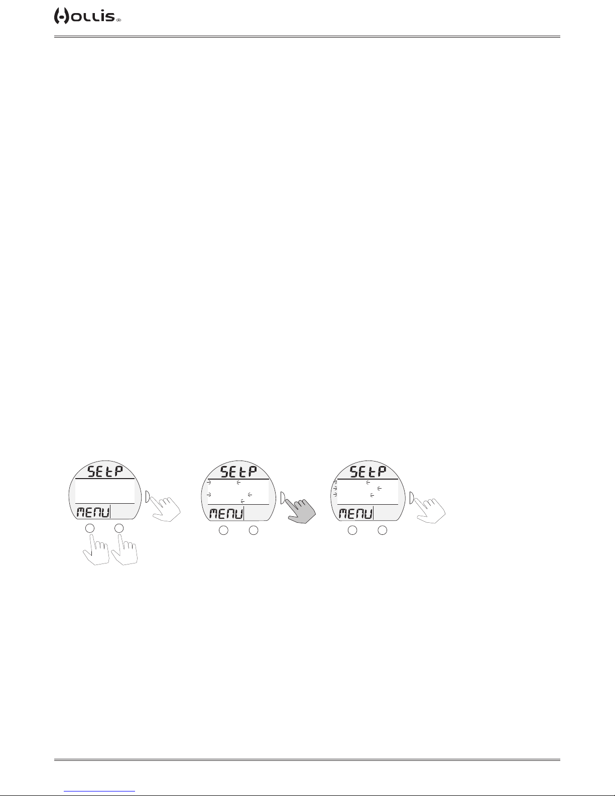
TX1 He OPERATING MANUAL
TAP
TAP
TAP
TAP
SET P (Preview) Menu, information includes:
> Graphics SEt P and MENU.
Using this menu, you can chose up to 4 items (Set Points that have been entered) for display on a Preview screen
that can be accessed from the Surface Main Menu (see page 19).
Up to 4 items can be selected from the following menu list.
> GAS 1 SET.
> GAS 2 SET.
> GAS 3 SET.
> GAS 4 SET.
> GAS 5 SET.
> GAS 6 SET.
> DEPTH AL SET.
> EDT AL SET.
> TP AL SET.
> END AL SET.
> WOB AL SET
> ICD AL SET
> DEEP STOP SET.
> SAFETY STOP SET.
> GF SET
> LAST STOP SET
> GLO DURA SET.
> MAX DEPTH
> TMT1 SET
> TMT2 SET
> TMT3 SET
> TMT4 SET
> TMT5 SET
> TMT6 SET
Set P Menu
(PZ+)
FTM
CF
GAS5 SET
GAS6 SET
DEPTH AL SET
>EDT AL SET
TLBG
PO2
M
SURF
>
BAR
>
PSI
GTR
TAT
min
A
or
S
TLBG
to select
Set P Menu
(selected items ash)
(PZ+)
FTM
CF
GAS5 SET
GAS6 SET
DEPTH AL SET
>EDT AL SET
PO2
M
SURF
>
S
BAR
>
PSI
GTR
TAT
min
A
HOLD
to save
Set P Preview
(only selected items display)
(PZ+)
FTM
CF
>GAS5 SET
>DEPTH AL SET
>EDT AL SET
TLBG
PO2
M
SURF
>
S
BAR
>
PSI
GTR
TAT
min
A
to Set Menu
or deselect
downup
to scroll cursor (>)
Once 4 items are selected (ashing), another item cannot be toggled to ash until one of the ashing items is toggled to solid.
When satised that those items ashing (up to 4) are what you want for the Preview screen, exit to the Set Menu.
© 2002 DESIGN (2014)
33
Doc. 12-4101-r06 (1/21/14)
Page 34

TX1 He OPERATING MANUAL
DIVE MODE
FEATURES
© 2002 DESIGN (2014)
34
Doc. 12-4101-r06 (1/21/14)
Page 35
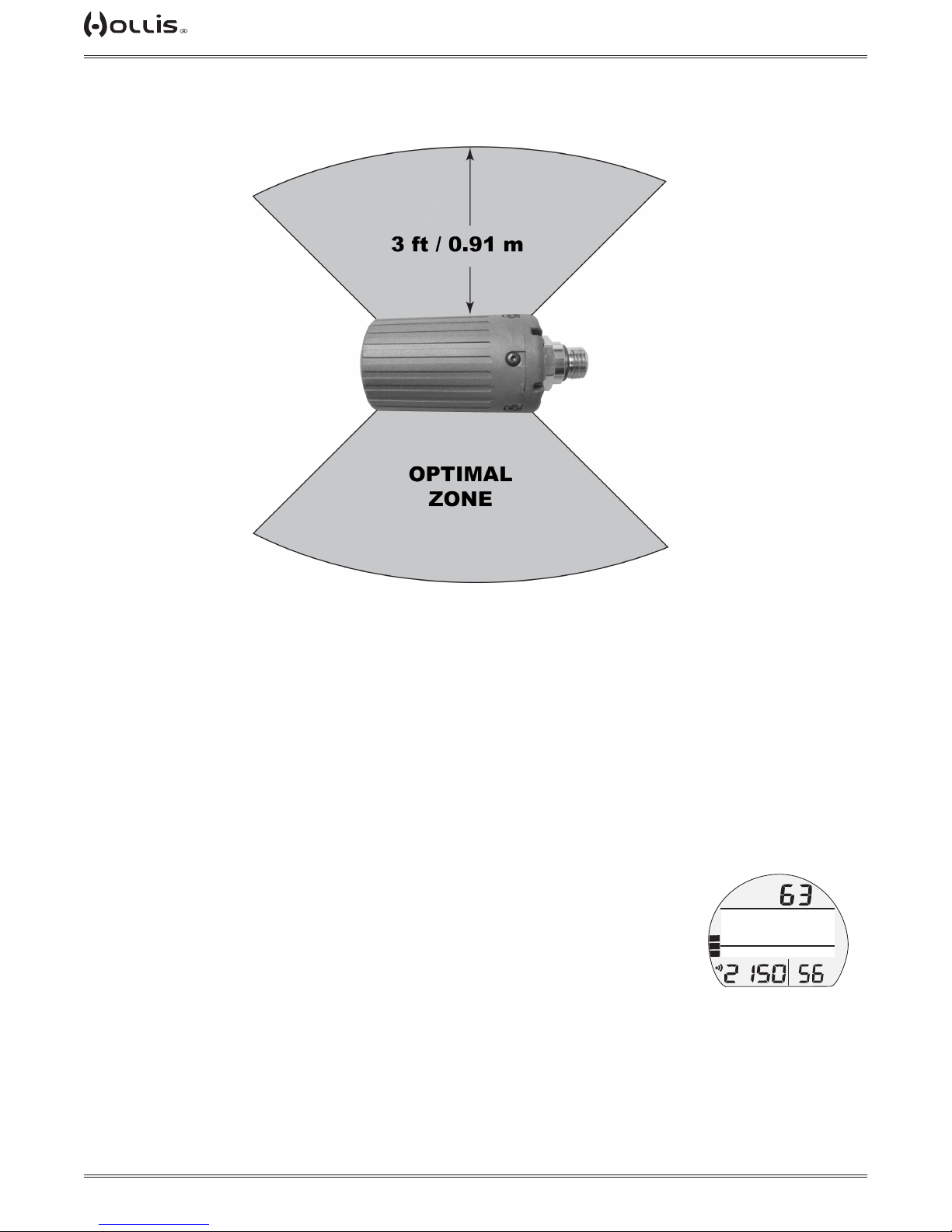
TX1 He OPERATING MANUAL
PROXIMITY OF THE TMTS (TRANSMITTERS) AND TX1 HE
The TMTs emit low frequency signals that radiate out in semicircular patterns parallel to the length dimension of the TMT. A coiled antenna inside the TX1 He wrist unit
receives the signals when it is positioned within a zone parallel to or at a 45 degree
angle to the TMT as illustrated.
The TX1 He cannot effectively receive a signal when it is held out to the sides of the
TMT or held at distances greater than 3 feet (0.91 meters) in front of the TMT. Best
reception is achieved when the TX1 He is within less than 3 feet (0.91 meterS) of the
TMT.
When installed into the high pressure ports of the Regulator First Stages, the TMTs
must be positioned so that they face horizontally outward from the Tank Valves.
Link Interruption Underwater
During a dive, you may at times move the TX1 He out of the signal pattern of the
TMT, resulting in a temporary loss of the Link signal. The Link will be restored within
4 seconds after the TX1 He is moved back into its correct position.
An interruption may also occur while the TX1 He is within 3 feet (1 meter) of a run-
ning DPV, or shortly after a Strobe ashes. The Link will be restored within 4 seconds
after the TX1 He is moved out of that area.
If the Link is not restored within 15 seconds, the Audible will sound, and the graphics
LOST TMT, Pressure value, and Link icon will ash until it is restored.
42
LOST TMT
TLBG
PO2
BAR
LOSS OF LINK
PSI
FTM
NDC
GAS4
GTR
TAT
min
© 2002 DESIGN (2014)
35
Doc. 12-4101-r06 (1/21/14)
Page 36
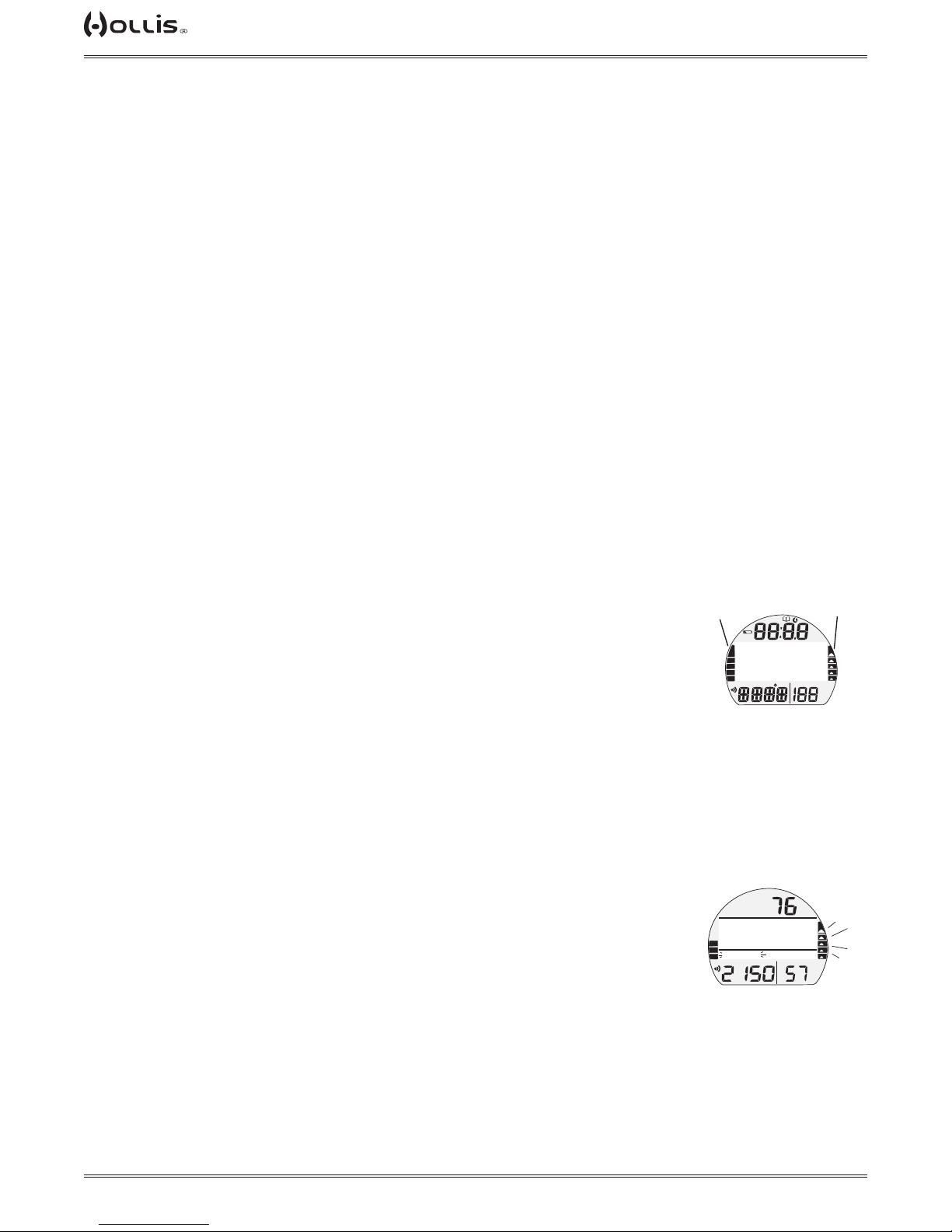
TX1 He OPERATING MANUAL
WET ACTIVATION
The TX1 He is congured with contacts that will automatically activate Dive Mode
when the space between the contacts is bridged by a conductive material (immersed
in water) and it senses a Depth of 5 FT (1.5 M).
The contacts are the metal pins of the PC Interface Data Port and the stems of the
buttons.
When Wet Activation is set OFF, the TX1 He will not enter Dive Mode unless it is rst
activated by push button and operating in a surface mode or it is a repetitive dive.
SMARTGLO® BACKLIGHT
The TX1 He is congured with a sensor that measures the intensity of ambient light.
This (Smartglo) saves battery power by allowing the Backlight to only come on when
light level is low.
To activate the SmartGlo Backlight >> press/release the S button less than 2 seconds.
• If ambient light level is low, the Backlight will activate and illuminate the display for
the Duration time set (0, 5, 10, or 15 seconds).
• Pressing any button while the Backlight is on will reset the timer, keeping it on for
the duration time set.
NOTE: Extensive use of the Backlight reduces estimated Battery life. Also,
the Backlight does not operate during a Low Battery Condition or when the
TX1 He is connected to a PC.
BAR GRAPHS
The TX1 He features 2 bar graphs, one on each side of the LCD.
> The one on the left represents inert gas (nitrogen and helium) loading. It is referred
to as the TLBG (Tissue Loading Bar Graph).
> The one on the right represents ascent rate. It is referred to as the VARI (Variable
Ascent Rate Indicator).
TLBG
The TLBG represents your relative No Deco or Deco status. The lower 4 segments
represent No Deco status and the fth at the top indicates a Deco condition. As your
Depth and Elapsed Dive Time increase segments add, and as you ascend segments
recede indicating that additional no deco time is available.
The TX1 He monitors 12 different inert gas compartments simultaneously and the
TLBG displays the one that is in control of your dive at any given time.
VARI
The VARI provides a visual representation of ascent speed (i.e., an ascent speedometer).
The segments represent two sets of speeds which change at a reference depth of 60
FT (18 M). Refer to the chart. When ascent is too fast, all segments of the VARI and
the graphics TOO FAST will be displayed ashing until ascent is
slowed.
a
TX1
DIAGNOSTICS
TLBG
PO2
BAR
PSI
BAR GRAPHS
FTM
NDC
46
TOO FAST
TLBG
ASCENT TOO FAST
GAS1
PO2
BAR
PSI
b
FTM
SURF
VARI
GTR
TAT
min
VARI
GTR
TAT
min
! WARNING: At depths greater than 60 FT (18 M), ascent rates should not exceed 60 FPM (18 MPM). At depths of 60 FT (18 M) and shallower, ascent rates
should not exceed 30 FPM (9 MPM).
© 2002 DESIGN (2014)
36
Doc. 12-4101-r06 (1/21/14)
Page 37

TX1 He OPERATING MANUAL
ALGORITHM
BUHLMANN ZHL-16C WITH GRADIENT FACTOR
The TX1 He uses the Bühlmann ZHL-16c algorithm utilizing user selectable gradient
factors. The user has full control of gradient factors (GF), to adjust dive proles and
conservatism.
GRADIENT FACTOR (GF)
Gradient factors are a method for setting decompression conservatism. This is accomplished by limiting what pressure gradient, imposed on the leading theoretical
tissue compartment, is permissible before further ascent.
M-value is the maximum inert gas saturation in the leading (currently limitting) tissue
compartment that the ZHL-16c model predicts will not result in DCS symptoms if the
diver were to ascend further.
Gradient factors limit the diver to ascend only with a fraction (factor) of the algorithm's
M-value. For example, a gradient factor of 0% would mean no off gassing is taking place in the leading tissue compartment. Gradient factors of 100% would be the
maximum allowable off gassing rate permitted by the algorithm.
The settings on the TX1 He allow for a GF Low and a GF High setting. The TX1 He
requires the diver to select between 5 GF presets or custom settings (0% to 90%) for
both the GF Low and GF High settings. The GF Low setting allows for the setting of
the gradient factor of the rst decompression stop, effecting what depth the rst ceiling will be. The GF High setting allows the user to select the tissue saturation level
the TX1 He will allow for surfacing, from the last deco stop.
The TX1 He does not allow for the selection of the GF for each individual deco stop.
Though by changing the GF Low and High settings, the depth of the rst deco stop
and the general slope of the ascent prole can be manipulated to adjust the conservatism. This provides the diver with greater exibility for planning the conservatism of
any dive.
When choosing GF settings, consider your physical condition, the dive conditions,
your personally accepted level of decompression risk. The Hollis HDDO software
may be utilized to explore how each setting effects any particular dive prole.
© 2002 DESIGN (2014)
37
Doc. 12-4101-r06 (1/21/14)
Page 38

TX1 He OPERATING MANUAL
DEEP STOP (DS)
When the DS selection is set On, it will trigger during NORM No Deco dives when
you descend to 80 FT (24 M) and calculate (and continually update) a Stop Depth
equal to 1/2 the Max Depth.
While 10 FT (3 M) deeper than the calculated DS, you will be able to access a DS
Preview screen that will display the current Deep Stop Depth (calculated) and Time
(xed at 2 min) for 5 seconds then return to the Main.
Upon initial ascent to within 10 FT (3 M) below the calculated Stop Depth, a DS
screen displaying a Stop Depth at 1/2 the Max Depth will appear with a Countdown
Timer beginning at 2:00 (min:sec) and counting down to 0:00.
> If you descend 10 FT (3 M) below, or ascend 10 FT (3 M) above, the calculated
Stop Depth for 10 seconds during the countdown, the No Deco Main will replace the
DS Main display and the DS feature will be disabled for the remainder of that dive.
There is no Penalty if the DS is ignored.
> In the event that you enter Deco, exceed 190 FT (57 M), or a High O2 condition
(≥80%) occurs, the DS will be disabled for the remainder of that dive.
> The DS is disabled during a High PO2 Alarm condition (≥ Set Point).
SAFETY STOP (SS)
If set On:
Upon ascent to within 5 FT (1.5 M) deeper than the SS Depth set for 1 second on a
No Deco dive in which Depth exceeded 30 FT (9 M) for 1 second, a beep will sound
and a SS at the Depth set will appear on the Main display with a countdown beginning at the SS Time set and counting down to 0:00 (min:sec).
• If the SS was set for Off or Timer, this display will not appear.
• In the event that you descend 10 FT (3 M) deeper than the Stop Depth for 10
seconds during the countdown, or the countdown reaches 0:00, the No Deco Main
screen will replace the SS Main screen which will reappear upon ascent to
within 5 FT (1.5 M) deeper than the Safety Stop Depth set for 1 second.
• In the event that you enter Deco during the dive, complete the Deco obligation, then
descend below 30 FT (9 M); the SS Main will appear again upon ascent to within 5
FT (1.5 M) deeper than the SS Depth set for 1 second.
• If you surface prior to completing the SS, it will be disabed for the remainder of that
dive.
• There is no Penalty if you surface prior to completing the SS or ignore it.
If set for Timer On:
Upon ascending to 20 FT (6 M) for 1 second on a No Deco dive in which Depth
exceeded 30 FT (9 M) for 1 second, a beep will sound and a Timer will appear (if set
On) displaying 0:00 (min:sec) until started.
• If the SS was set for Off or On, the Timer display will not appear.
• If you descend deeper than 30 FT (9 M) for 10 seconds, the No Deco Main will replace the Timer screen which will reappear upon ascent to 20 FT (6 M) for 1 second.
• If you enter Deco, or a High O2 alarm condition occurs (100%), while the SS Timer
is active, the SS function will be disabled for the remainder of that dive.
• If you surface prior to completing the SS, it will be disabled for the remainder of that
dive.
DIVE TIME REMAINING (DTR)
The TX1 He constantly monitors nitrogen loading and oxygen accumulation, and will
display whichever time is the least amount available as DTR on the No Deco Dive
Main screen. The graphic NDC, or OTR, will identify which time is being
displayed.
© 2002 DESIGN (2014)
38
Doc. 12-4101-r06 (1/21/14)
Page 39
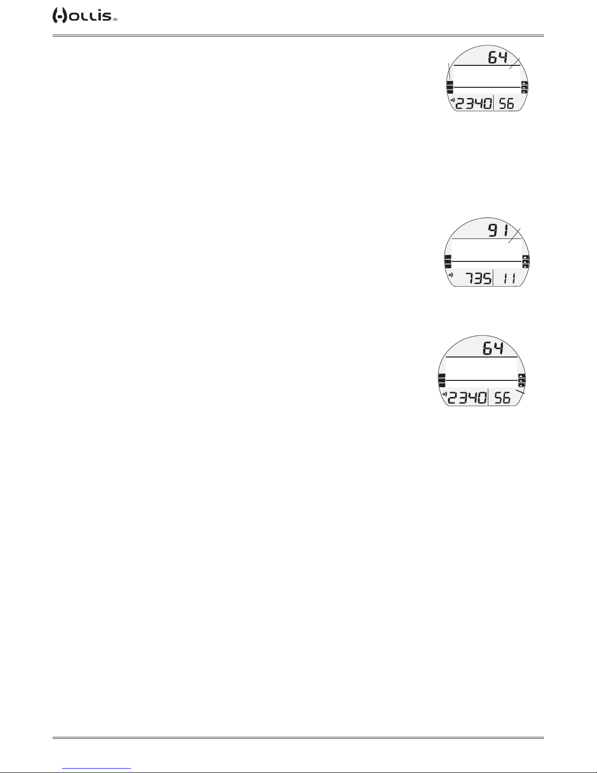
TX1 He OPERATING MANUAL
No Deco DTR (NDC)
NDC is the maximum amount of time that you can stay at your present Depth before
entering Deco. It is calculated based on the amount of inert gas (nitrogen and helium) absorbed by hypothetical tissue compartments. The rates each of these compartments absorb and release inert gas is mathematically modeled and compared
against a maximum allowable inert gas level.
Whichever one is closest to this maximum level is the controlling compartment for
that Depth. Its resulting value will be displayed as NDC time (a) and graphically as
the TLBG.
As you ascend, the TLBG segments will recede as control shifts to slower compartments. This is a feature of the decompression model that is the basis for multilevel
diving, one of the most important advantages that Hollis dive computers offer.
O2 Time Remaining (OTR)
During Nitrox and Oxygen operation, O₂ accumulation during a dive or 24 hour period
is displayed as a percent of O₂ saturation allowed per dive or per day. Max allowed
(100%) is 300 OTU.
When time remaining before reaching the O₂ limit becomes less than NDC, calculations for that Depth will be controlled by O₂. Then OTR will be displayed as DTR on
the Dive Main.
GAS TIME REMAINING (GTR)
b
48
DS
aır
TLBG
PO2
BAR
NO DECO MAIN
(NDC is DTR)
3
aır
TLBG
PO2
BAR
NO DECO MAIN
(OTR is DTR)
NDC
GAS1
PSI
OTR
GAS2
PSI
a
FTM
VARI
GTR
TAT
min
a
FTM
VARI
GTR
TAT
min
GTR is the time your current selected gas will last at the present Depth with the Tank
Pressure reserve that you selected during setup (End Pressure Alarm Setting). It is
displayed on the Dive Main screens.
GTR is calculated using a patented algorithm that is based on a diver's individual
Air Consumption Rate and Current Depth. The active tank transmitter pressure is
measured once each second, and an average rate of Consumption is calculated over
a 90 second period. This Rate of Consumption is then used in conjunction with the
Depth to predict the remaining time the active gas will last at the present depth and
breathing rate.
Gas Consumption and Depth are continuously monitored and GTR reects any
change in circumstances. For example, when you suddenly nd yourself swimming
against a strong current and begin breathing more rapidly, the TX1 He will recognize
the change and adjust GTR accordingly.
NOTE: GTR ONLY tracks the active gas transmitter. It does not account for
additional available tanks with transmitters you may be carrying ie. deco
tanks, travel gases, or pony tanks.
WARNING: Due to the TX1 He design parameters, multiple transmitters and
routine use of multiple tanks, GTR does not account for the ascent gas needed to surface. Ensure that you start your ascent with adequate gas reserves
(GTR reading). Programming a conservative End Pressure Alarm Setting for
the planned depth will enhance your safety.
48
DS
aır
TLBG
PO2
BAR
NO DECO MAIN
(GTR is 56 min)
NDC
GAS1
PSI
FTM
VARI
GTR
a
TAT
min
GTR Alarm
When GTR decreases to 5 minutes, the Audible will sound and the GTR time digits
and graphic AIR TIME will ash. If it decreases to 0, the Audible will sound again.
The time digits and graphic will continue to ash until GTR becomes greater than 5
minutes.
© 2002 DESIGN (2014)
39
Doc. 12-4101-r06 (1/21/14)
Page 40

TX1 He OPERATING MANUAL
TOTAL ASCENT TIME (TAT)
Available only on an alternate (ALT) screen when in a decompression requirement,
TAT displays the total time to the surface. For calculation, TAT assumes a strict following of the current decompression schedule and prescribed gas switches. It takes
into acount all decompression stops and a standard ascent time between stops. Any
delays in the decompression schedule, on the part of the diver, will cause the TAT to
adjust according to a revised decompression schedule.
FTMAX
250
DECO ALT 2
(TAT 18 min)
EDT
47
FTM
SURF
GTR
TAT
TAT
min
min
© 2002 DESIGN (2014)
40
Doc. 12-4101-r06 (1/21/14)
Page 41

TX1 He OPERATING MANUAL
NORM DIVE
OP MODE
© 2002 DESIGN (2014)
41
Doc. 12-4101-r06 (1/21/14)
Page 42

NORM DIVE SCREENS
TAP
TAP
TAP
TAP
Norm Dive Main
(default)
TX1 He OPERATING MANUAL
Norm Dive Alt 1 Norm Dive Alt 2 Norm Dive Alt 3
12
TX 15/45
TLBG
PO2
BAR
PSI
M
FTM
NDC
GAS2
GTR
A
FTM
SURF
S
VARI
TAT
min
10:55
PO2
M
A
BAR
S
GTR
TAT
min
A
FTMAX
250
M
EDT
FTM
SURF
47
A
O2 SAT
GF
S
GTR
TAT
min
45%
TX 15/45
28
GAS2
PO2
BAR
M
S
A
back to main
No Deco Main, information includes**:
**Which information is displayed is determined by the SET D menu selection saved during setup on the surface prior to the
dive.
> Current Depth with FT (or M) icon.
> DTR (up to 999 min) with graphic NDC (or OTR), dashes ( - - ) if on the surface.
> EDT (up to 999 min) with graphic, if set for display.
> Max Depth with graphic FT (or M) MAX, if set for display.
> Pressure (or letters SPG if no tmt) with PSI (or BAR) and Link icons, if Rcvr and TMT are active, ashing when
Link is lost.
> GF (Gradient Factor) if set to display on Dive Main.
> Graphics GAS NAME and GAS# for actual gas
> GTR (up to 199 min) with icons, blank if no TMT, or O2 Data is selected for display, dashes ( - - ) if on the surface.
> O2 Data, if set for display - including % O2 accumulated with graphic O2 SAT, PO2 value with icon, and FO2 set
for Gas
indicated (one in use).
> DS graphic - if Deep Stop is set On and has triggered.
> TLBG, VARI - if they apply.
No Deco ALT 1, information includes:
> Graphic ALt.
> Time of day (hr:min) with graphic A (or P) if 12 hour mode.
> Temperature with ° icon and graphic F (or C).
No Deco ALT 2, information includes:
> Graphic ALt.
> Max Depth with graphic FT (or M) MAX, blank if on Main*.
> EDT (min) with graphic, blank if on Main*.
> Pressure with PSI (or BAR) and Link icons, blank if on Main.
> GTR (min) with icons, blank if on Main, dashes ( - - ) if on the surface.
> TAT** Total Ascent Time (up to 199 min) with TAT and min icons.
*If max Depth & EDT are both on the Main, ALt 3 becomes ALt 2.
**Only displayed if in Decompression.
No Deco ALT 3,
> Graphic ALt.
> %O2 accumulated with graphic O2 SAT (if not already displayed on Dive Main).
> GF (Gradient Factor). GF does not display here if already displayed on Dive Main.
> PO2 value (x.xx ATA) with icon, dashes (--) if on the surface. (Alternately, gas pressure displays if PO2 is set to
display on Dive Main.)
> Graphics GAS NAME and GAS# for actual gas
> Tank pressure with psi (or bar) and link icon (if linked to a tmt).
© 2002 DESIGN (2014)
42
Doc. 12-4101-r06 (1/21/14)
Page 43
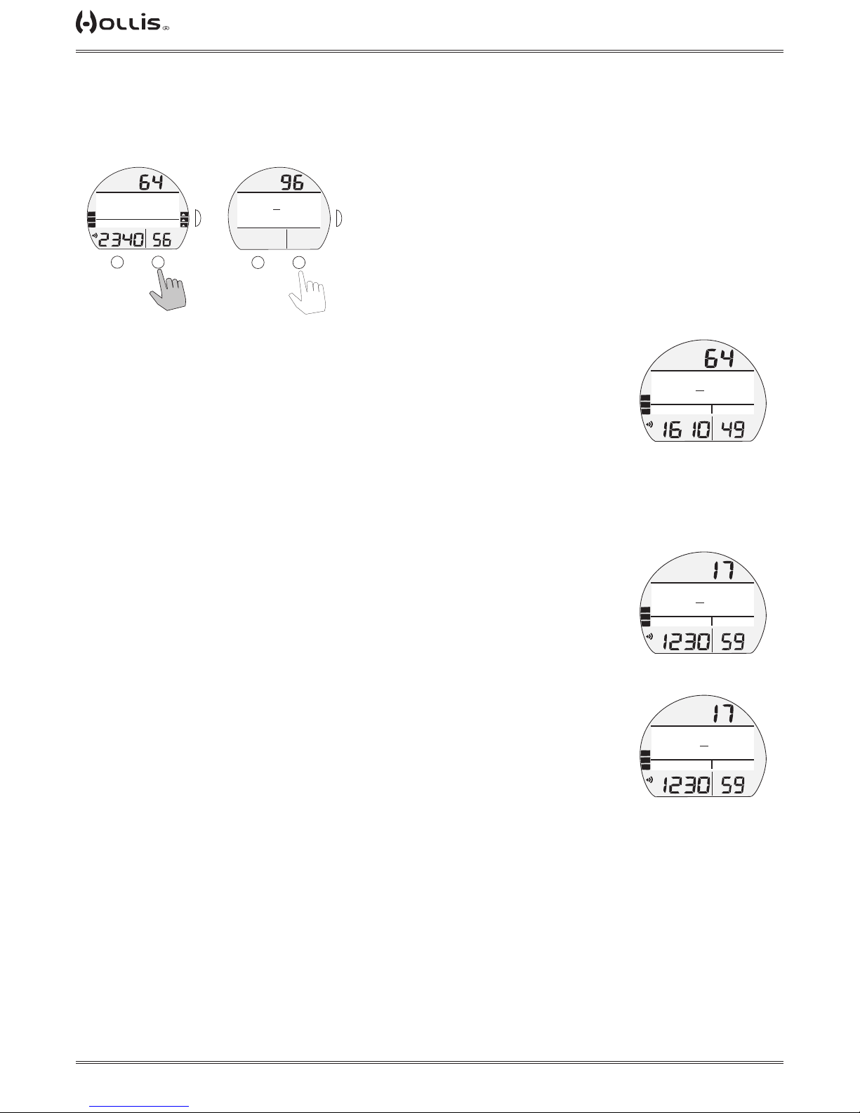
TX1 He OPERATING MANUAL
TAP
DEEP STOP PREVIEW, information includes:
> Current Depth with FT (or M) icon.
> Graphic DEEP STOP with Stop icon (arrows and bar).
> Stop Depth with graphic FT (or M) and countdown Time as 2:00 (min:sec).
Norm Dive Main
(deep stop triggered)
Deep Stop Preview
(default)
DS
aır
TLBG
48
PO2
BAR
PSI
M
FTM
NDC
GAS1
GTR
TAT
min
A
HOLD
DEEP STOP
FT
S
VARI
46
M
>
>
2:00
A
FTM
SURF
GTR
TAT
min
back to main
S
DEEP STOP MAIN, information includes:
> Current Depth with FT (or M) icon.
> Graphic DEEP STOP with Stop icon (arrows and bar).
> Stop Depth with graphic FT (or M) and countdown Time as 2:00 (min:sec).
> DTR (up to 999 min) with graphic NDC.
> Pressure with PSI (or BAR) and Link icons.
> Graphics GAS NAME and GAS# for actual gas.
> GTR (up to 199 min) with icons.
> TLBG, VARI - if they apply.
Deep Stop Alt Screens, information is similar to No Deco ALts.
SAFETY STOP MAIN, information includes* -
> Current Depth with FT (or M) icon.
> Graphic SAFETY STOP with Stop icon (arrows and bar).
> Stop Depth set with graphic FT (or M) with set time (min:sec) counting down to
0:00,
> Graphic TIMER, counting up from 0:00 to 9:59 (min:sec).
> DTR (up to 999 min) with graphic NDC.
> Pressure with PSI (or BAR) and Link icons.
> Graphics GAS NAME and GAS# for actual gas.
> GTR (up to 199 min) with icons.
> TLBG, VARI - if they apply.
Safety Stop Alt Screens, information is similar to No Deco ALts.
FTM
DEEP STOP
>
FT
FT
63
>
1:23
NDC 9
TLBG
PO2
DEEP STOP MAIN
SAFETY STOP
15
NDC 41
TLBG
PO2
SAFETY STOP MAIN
(set for depth/time prior to dive)
SAFETY STOP
TIMER
NDC 41
TLBG
PO2
SAFETY STOP MAIN
(set for run time prior to dive)
BAR
FT
FT
BAR
FT
BAR
PSI
>
PSI
>
PSI
GAS1
GTR
min
FTM
>
2:36
GAS3
GTR
min
FTM
>
2:36
GAS3
GTR
min
TAT
TAT
TAT
© 2002 DESIGN (2014)
43
Doc. 12-4101-r06 (1/21/14)
Page 44
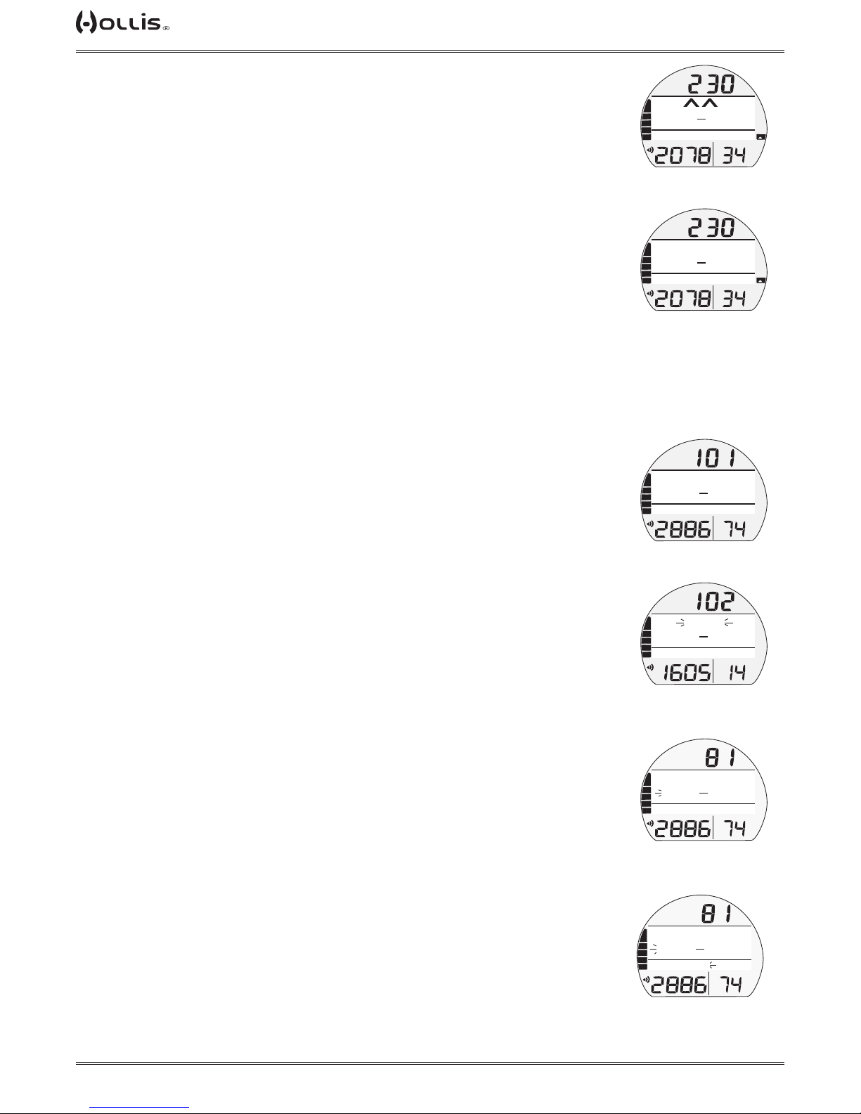
TX1 He OPERATING MANUAL
DECOMPRESSION
Decompression mode activates when theoretical No Decompression time and depth
limits are exceeded.
Upon entry into Deco, the Audible will sound during which the alarm LED and full
TLBG will ash. Two Up Arrows will also ash, until within 10 FT (3 M) of and below
the required Stop Depth (the Stop Zone).
> Once within 10 FT (3 M) of and below the required Stop Depth (the Stop Zone), the
full Stop icon (smaller Up and Down Arrows with Stop Bar) will be displayed solid.
Managing Deco Stops
To fulll your decompression obligation, you should make a safe controlled Ascent
to a depth slightly deeper than, or equal to, the required Stop Depth indicated and
decompress for the Stop Time indicated.
The amount of decompression credit time that you receive is dependent on Depth,
with slightly less credit given the deeper you are below the Stop Depth indicated.
You should stay slightly deeper than the required Stop Depth indicated until the next
shallower Stop Depth appears. Then, you can slowly ascend to, but not shallower
than that indicated Stop Depth.
DECO STOP MAIN, information includes:
> Current Depth with FT (or M) icon.
> Graphic DECO STOP with Stop icon (arrows and bar).
> Stop Depth with graphic FT (or M) and Stop Time (up to 99 min) with graphic MIN.
> Pressure with PSI (or BAR) and Link icons.
> GTR (up to 199 min) with icons.
> TLBG, VARI - if they apply.
> GAS # with gas name, AIR, NX (FO2), or TX (FO2/FHe), will ash if a gas switch is
recommended.
Deco Stop Alt Screens, information is similar to No Deco ALts.
MISSED DECO
Warning >> When the depth is shallower than the deepest Stop Depth (for less than 1 minute).
Alarm >> When the depth is shallower than the deepest Stop Depth (for more than 1 minute).
The warning will sound an audible alarm for 10 seconds or until acknowledged.
The stop depth will ash while a down arrow appears until returning below the deco
stop depth.
If the diver stays above the stop for more than 1 minute the alarm will activate. The
audible will sound again for 10 seconds or until acknowledged. In addition to the
depth the message MISSED DECO will also ash until returning below the deco stop
depth.
FTM
>
>
>
FT
100
TX 15/45
TLBG
PO2
BAR
DECO ENTRY
(1 of 2 alternating)
DECO ENTRY
FT
100
TX 15/45
TLBG
PO2
BAR
DECO ENTRY
(2 of 2 alternating)
DECO STOP
FT
100
AIR
TLBG
PO2
BAR
DECO STOP MAIN
GAS4 AIR
FT
100
TX 15/45
TLBG
PO2
BAR
DECO STOP MAIN
(gas switch indicated)
DECO STOP
FT
100
AIR
TLBG
PO2
BAR
MISSED DECO WARNING
>
>
>
>
MIN
2
>
GAS2
FTM
MIN
2
GAS2
FTM
MIN
2
GAS4
FTM
MIN
2
GAS2
FTM
MIN
2
GAS4
VARI
GTR
TAT
min
VARI
GTR
TAT
min
GTR
TAT
min
GTR
TAT
min
GTR
TAT
min
PSI
>
PSI
>
PSI
>
PSI
PSI
If the warning and alarm are ignored, the TX1 He will continue calculating a less
conservative decompression schedule at the depth the diver is currently at unless a
gradient factor of 90 is exceeded. If the ascent schedule exceeds a gradient factor
90 the computer will enter Deco Ceiling Violation (see the following).
© 2002 DESIGN (2014)
44
FTM
DECO STOP
>
FT
100
MISSED DECO
TLBG
PO2
BAR
MISSED DECO ALARM
Doc. 12-4101-r06 (1/21/14)
MIN
2
GAS4
PSI
GTR
TAT
min
Page 45
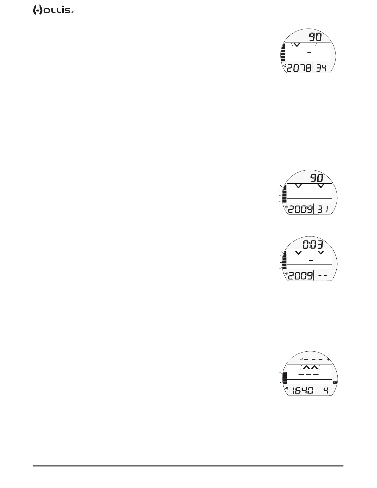
TX1 He OPERATING MANUAL
DECO CEILING VIOLATION (DCV)
The Deco Ceiling Violation triggers when the ascent exceeds a GF (gradient factor)
of 90 for less than 5 minutes regardless of GF settings. During which no off gassing
credit will be given, meaning Deco Stop Time and TAT will not decrease.
The Audible will sound during which the alarm LED will ash for 10 seconds or until
it is acknowledged. A Down Arrow will also ash until descent is made to below the
required Stop Depth. Then it is removed.
If the condition is corrected within 5 minutes, operation will then resume in Deco or
No Deco mode.
If not corrected within 5 minutes and still underwater, operation enters Delayed Deco
Violation (see the following section).
If not corrected within 5 minutes and the diver has surfaced (omitting deco), the coputer will enter VGM (Violation Gauge Mode).
DELAYED DECO VIOLATION (DDV)
Once the ascent exceeds a GF 90 for more than 5 minutes, operation will enter Delayed Deco Violation. During which no off gassing credit will be given, meaning Deco
Stop Time and TAT will not decrease.
The Audible will sound during which the alarm LED and full TLBG will ash for 10
seconds. Two Down Arrows will ash until descent is made to below the required
Stop Depth.
When descent below the required Deco Stop Depth, operation will then resume in
Deco or No Deco mode.
5 minutes after surfacing from the dive, operation reverts to VGM (Violation Gauge
Mode).
After a full 10 minutes on the surface, the TX1 He will switch to VGM Surface Main
(Surface functions remain available).
DEPTH VIOLATION (DV)
Upon descent deeper than the depth limitation (400 ft/120 m) of the TX1 He, the Au-
dible will sound during which the alarm LED will ash for 10 seconds. Two Up Arrows
and the loaded segments of the TLBG will also ash.
>
PSI
PSI
PSI
FT
GAS2
FTM
>
GAS2
SURF
>
GAS2
GTR
TAT
min
>>
GTR
TAT
min
>>
GTR
TAT
min
>>
GF>90
100 FT 2 MIN
TX 15/45
TLBG
PO2
BAR
DECO CEILING VIOLATION
>>
GF>90
100 FT 7 MIN
TX 15/45
TLBG
PO2
BAR
DELAYED DECO VIOLATION
(during audible)
>>
GF>90
100 FT 7 MIN
TX 15/45
TLBG
PO2
BAR
DELAYED DECO VIOLATION
(on surface < 5 min)
The Decompression Calculations will continue if data is accurate. Though they will
not be visible until ascending above 400 ft/120 m.
The Log for that dive will record 3 dashes as the Max Depth.
DV MAIN, information includes -
> Current Depth ashing as 3 dashes ( - - - ) with FT (or M) icon.
> (2) Up Arrows ashing, until at/above MOD.
> DTR as 3 dashes ( - - - ) with graphic NDC.
> Pressure with PSI (or BAR) and Link icons.
> Graphics GAS NAME and GAS# for actual gas.
> GTR (up to 199 min) with icons.
> TLBG - ashing for the remainder of that dive.
> VARI while ascending.
© 2002 DESIGN (2014)
45
FT
>>
>>
NDC
TX10/40
TLBG
PO2
DEPTH VIOLATION
Doc. 12-4101-r06 (1/21/14)
GAS5
BAR
PSI
VARI
GTR
TAT
min
Page 46
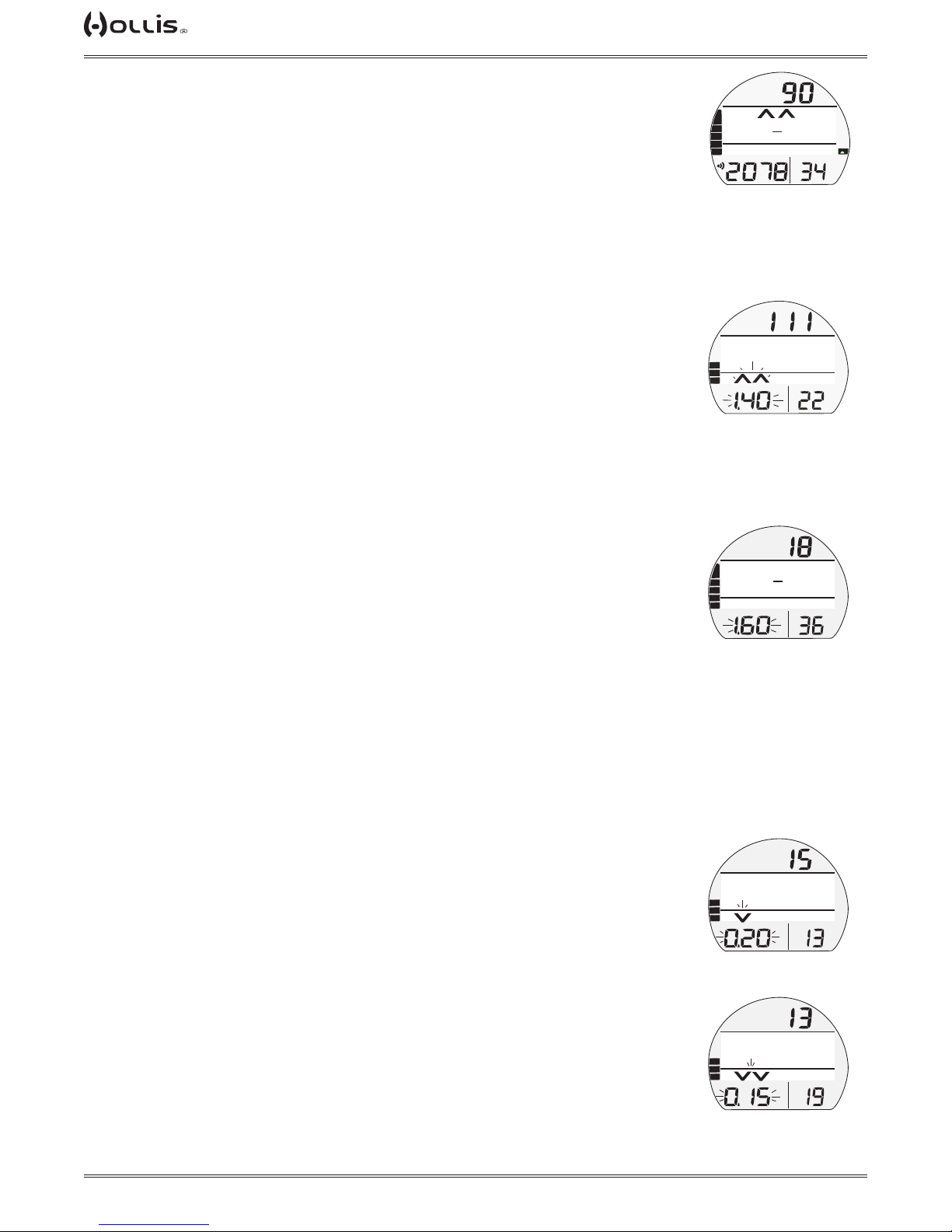
TX1 He OPERATING MANUAL
GAS SWITCH WARNING (AFTER DECO ENTRY)
Warning >> when the actual gas is not the best gas at current depth.
When there is required decompression, the TX1 He shall warn the diver about switching to the best active gas available. The best gas is the gas with highest PO2 that is
below the PO2 MAX at current depth. When there is a better active gas available; the
audible sound twice and the message SWITCH TO (gas name) will be displayed until
the gas is switched or the warning is acknowledged.
HIGH PO2
Alarm >> at Set Point value, except in Deco then at 1.60 only.
When partial pressure of oxygen (PO2) increases to the Warning level; the Audible
will sound during which an Up Arrow and the PO2 value with icon will ash in place of
Pressure.
The High PO2 Alarm level, the Audible will sound again during which (2) Up Arrows
and the PO2 value with icon will ash in place of Pressure.
> After the Audible is silenced, Pressure is restored, and the Up Arrows remain on
solid until PO2 decreases below the alarm level, at which time one of the Up Arrows
is removed.
High PO2 during Deco
The PO2 alarm that was set does not apply when in Deco.
If PO2 reaches 1.60, the Audible will sound during which the PO2 value with icon will
ash in place of Pressure.
> After the Audible is silenced, the PO2 value with icon will alternate with Pressure
once each minute*.
*PO2 will be displayed for 10 seconds, then Pressure will be displayed for 50 seconds once
each minute until PO2 decreases below 1.60, then PO2 will not be displayed.
FTM
>>
>>
>
FT
30
SWITCH TO NX 40
TLBG
PO2
BAR
GAS SWITCH WARNING
(after deco entry)
MIN
2
>
PSI
VARI
GTR
TAT
min
FTM
NDC
6
>
>
TLBG
PO2
HIGH PO2 ALARM
(during audible)
20
NX 80
TLBG
PO2
PO2
HIGH PO2 ALARM
(during audible, in Deco)
GAS2
BAR
DECO STOP
>
FT
BAR
>
18
GAS3
GTR
TAT
min
FTM
MIN
GTR
TAT
min
LOW PO2
Warning (only during No Deco) >> at 0.17 ≤ PO2 < 0.21
Alarm >> at PO2 < 0.17
When partial pressure of oxygen (PO2) decreases to the Warning level; the Audible
will sound during which a Down Arrow and the PO2 value with icon will ash in place
of Pressure.
> After the Audible is silenced, Pressure is restored, and the Down Arrow remains on
solid until PO2 increases above 0.20 ATA.
If PO2 continues to decrease and reaches the Low PO2 Alarm level, the Audible will
sound again during which (2) Down Arrows and the PO2 value with icon will ash in
place of Pressure.
> After the Audible is silenced, Pressure is restored, and the (2) Down Arrows and
PO2 icon remain on (ashing) until PO2 increases above 0.17 ATA. At which time the
screen reverts to the Low PO2 Warning Screen until PO2 increases above 0.20 ATA.
28
>
TLBG
PO2
BAR
LOW PO2 WARNING
(during audible)
GAS4
NDC
22
>
>
NDC
TLBG
PO2
LOW PO2 ALARM
(during audible)
GAS4
BAR
FTM
GTR
TAT
min
FTM
GTR
TAT
min
© 2002 DESIGN (2014)
46
Doc. 12-4101-r06 (1/21/14)
Page 47
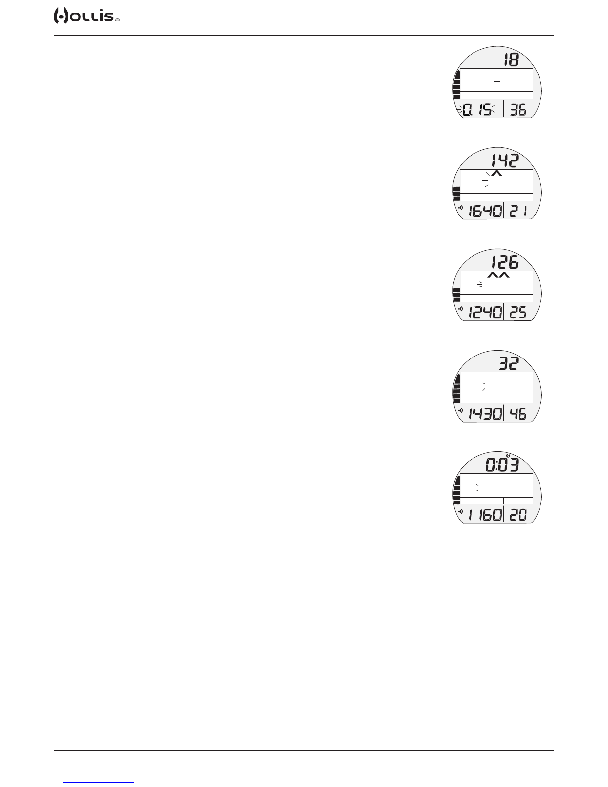
TX1 He OPERATING MANUAL
Low PO2 during Deco
If PO2 drops below 0.17 ATA, the Audible will sound during which the PO2 value with
icon will ash in place of Pressure.
> After the Audible is silenced, the PO2 value with icon will alternate with Pressure
once each minute*.
*PO2 will be displayed for 10 seconds, then Pressure will be displayed for 50 seconds once
each minute until PO2 increases above 0.17, then PO2 will not be displayed.
HIGH O2 SATURATION
Warning >> at 80 to 99% (240 OTU).
Alarm >> at 100% (300 OTU).
When O2 reaches the Warning level; the Audible will sound during which the O2
value with graphic %O2SAT and an Up Arrow will ash (in place of DTR) until the
audible is silenced. Then DTR will be restored. The Up Arrow will remain on solid until
O2 decreases below 80%.
If O2 reaches the Alarm level; the Audible will sound again during which (2) Up
Arrows and the O2 value 100 with graphic %O2SAT will ash until the audible is
silenced. Then O2 value with graphic %O2SAT will ash until on the surface.
High O2 during Deco
When O2 reaches the Warning Level; the Audible will sound during which the O2
value with graphic %O2SAT will ash in place of Stop Depth/Time with the graphic
DECO STOP until the Audible is silenced. Then Stop Depth/Time will be restored. No
indication (Up Arrow) is given to ascend.
When O2 reaches 100%, the Audible will sound again during which the O2 value
100 with graphic %O2SAT and (2) Up Arrows will ash in place of the graphic DECO
STOP until the audible is silenced. Then O2 value with graphic %O2SAT will ash
until on the surface, and the full TLBG remains on solid as a reminder of Deco.
High O2 on Surface
Upon ascent to 2 FT (0.6 M) for 1 second (surfacing), the Dive Main screen is displayed for 10 minutes with access to the Dive ALTs allowed. Surface Interval Time
with the SURF icon ashing will be displayed in place of Depth.
> If O2 is 100%, the value will ash on the Main until it is < 100%, then it will be
replaced with dashes and graphic NDC until 10 minutes elapse, then NORM Surface
Main.
FTM
DECO STOP
>
FT
20
TX 10/55
TLBG
PO2
PO2
BAR
LOW PO2 ALARM
(during audible in Deco)
NX 32
TLBG
BAR
O2 WARNING
(during audible)
100%
NX 32
TLBG
BAR
O2 ALARM
(during audible)
MIN
>
18
GAS6
FT
>
O2 SAT
80%
GAS3
PSI
FT
>
>
O2 SAT
GAS2
PSI
FT
GTR
TAT
min
GTR
min
GTR
min
DECO STOP
O2 SAT
80%
NX 36
TLBG
O2 WARNING
(during audible, in Deco)
100%
AIR
TLBG
O2 ALARM
(during audible, in Deco)
GAS2
BAR
PSI
GTR
min
O2 SAT
GAS2
BAR
PSI
GTR
min
> If you surface due to 100% O2 without having completed the Deco obligation, the
O2 value 100 with graphic % O2 SAT will ash for the rst 5 minutes. Then dashes
will be dipslayed and operation will enter VGM.
© 2002 DESIGN (2014)
47
Doc. 12-4101-r06 (1/21/14)
Page 48
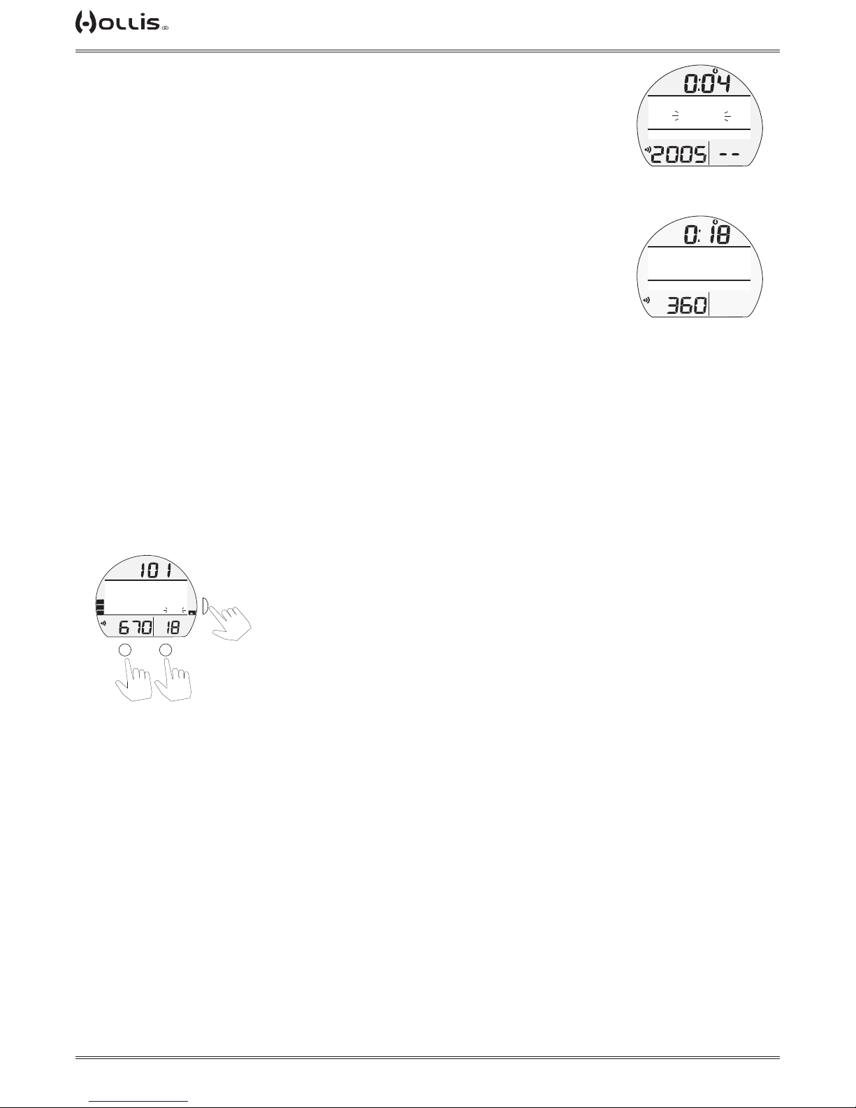
TX1 He OPERATING MANUAL
TAP
TAP
TAP
VIOLATION GAUGE MODE (VGM)
VGM turns the TX1 He into a digital instrument without any decompression or oxygen
related calculations or displays. This would be the result of severe decompression
violations or 100% O2 SAT condition.
The graphic VIOL ashes for the rst 10 minutes, then VIOLATION alternates with
NORM (each On 3 seconds) until unit shut down after 24 hours with no dives*.
*A full 24 hour surface interval must then be served before all functions are restored.
SURF
VIOLATION
NX 32
VGM MAIN
(on surface < 10 min)
GAS3
BAR
PSI
GTR
min
During that 24 hours, access to all menus and screens is available except those associated with decompression calculations such as Gas Menu, Plan Menu, Set GF,
Last Stop, Deep Stop, and Safety Stop. The Fly countdown timer provides the time
remaining (of the 24 hours required) before normal operation can resume with full
features and functions.
NORM DIVE MAIN MENU
Gas Switch
Similar to Surface Gas Switch (p. 22) with the inclusion of ICD warning when appropriate (see below).
Isobaric Counter Diffusion (ICD) Warning
During a gas switch the TX1 He will display a warning if there is a risk of ICD. The
risk must be accepted or declined by selecting YES or NO in the ICD Menu. If declined the TX1 He will not complete the gas switch. Instead it will return the user to
the Dive Main Screen.
> Graphic selection YES or NO.
FTM
!WARNING!
ISOBARIC COUNTER
FT
DIFFUSION
>CONFIRM YES
TLBG
PO2
BAR
PSI
or
M
S
VARI
GTR
TAT
min
A
to select
SURF
PO2
DIVE 4
BAR
PSI
GAS3
VIOL
NX 32
VGM MAIN
(on surface > 10 min)
to toggle YES/NO
Select Gases
Similar to the Surface Select Gases Menu (pg. 25).
© 2002 DESIGN (2014)
48
Doc. 12-4101-r06 (1/21/14)
Page 49
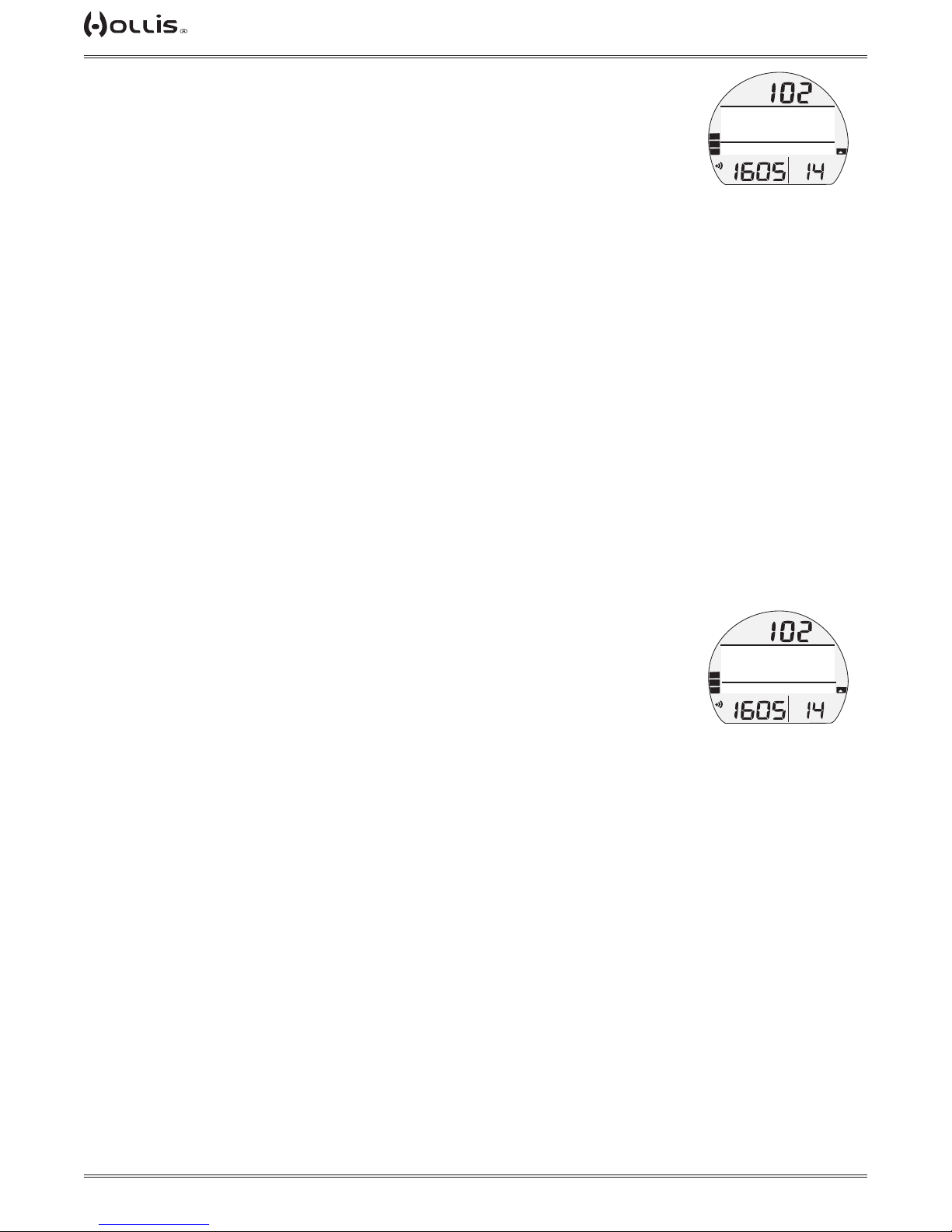
TX1 He OPERATING MANUAL
Depth Limits
This feature displays the depth limits of the current gas, based on MOD, END, WOB,
and HT physiological and alarm settings limits.
Depth Limit types:
MOD - is the Maximum Operating Depth calculated by the PO2 MAX set for the active gas.
END* - is the depth limit that the active gas reaches the Equivalent Nitrogen Depth
Alarm setting for the active gas.
WOB* - is the depth limit that the active gas reaches the Work Of Breathing Alarm
setting for the active gas.
HT - is the depth that the PO2 of the active gas equals 0.21 ATA.
*In this menu WOB and END stand for the limits set not the current (at actual depth) of the gas.
Information includes:
> Current Depth with FT (or M) icon.
> Tank Pressure with PSI (or BAR) and Link icons, if the receiver and transmitters are
active.
> PO2 value (x.xx ATA) with PO2 icon, replacing Pressure when option E is selected.
> GTR (up to 199 min) with GTR and min icons.
> TLBG with icon, Inert Gas Loading.
> VARI, Ascent Rate.
> Graphics MOD, END**, WOB**, and HT**.
> Graphic FEET (or METERS) LIMITS.
FTM
MOD END WOB HT
180 130 124 14
FEET LIMITS
TX 15/45
TLBG
PO2
DEPTH LIMITS
GAS3
BAR
PSI
VARI
GTR
TAT
min
**END, WOB, and HT are only displayed if their respective alarms are set ON and the actual
gas is Trimix.
Current END (w/O2 NARC Yes/No) WOB
This feature displays the current (at actual depth) END and WOB values of the active
gas.
Current Value types:
END - is the Equivalent Narcotic Depth value of the actual gas at the current depth.
NOTE: The TX1 He allows the inclusion of oxygen as a narcotic gas by setting O2 NARC to yes in the Utilities Menu. If set to yes, oxygen is considered equally narcotic as nitrogen. If O2 Narc is set to No, oxygen narcotic
effect will be disregarded in END calculations.
WOB - is the equivalent depth that AIR would have the same Work Of Breathing as
the actual (active gas) has at the current depth.
Information includes:
> Current Depth with FT or M icon.
> Graphics CURRENT.
> Graphics END (with the value) and WOB (with the value) of the actual gas*.
> Graphic FEET or METERS.
> Graphics GAS NAME (AIR, NX (FO2), or TX (FO2/FHe) and GAS# of the actual
gas.
> Tank Pressure with PSI (or BAR) and Link icons, if the receiver and transmitters are
active.
> PO2 value (x.xx ATA) with PO2 icon, replacing Pressure when option E is selected.
> GTR (up to 199 min) with GTR and min icons.
> TLBG with icon, Inert Gas Loading.
> VARI, Ascent Rate.
FTM
CURRENT
END 32 WOB 36
FEET
TX 15/45
TLBG
PO2
CURRENT END WOB
GAS3
VARI
BAR
GTR
PSI
TAT
min
*If FN2=0, the END shall not be calculated and 400 ft (or 120 m) shall be displayed as END value (N2 only). If any value is greater than 400 ft
(120 m), 400 ft (or 120 m) shall be displayed. 0 (zero) shall be displayed if any calculated value is negative.
© 2002 DESIGN (2014)
49
Doc. 12-4101-r06 (1/21/14)
Page 50
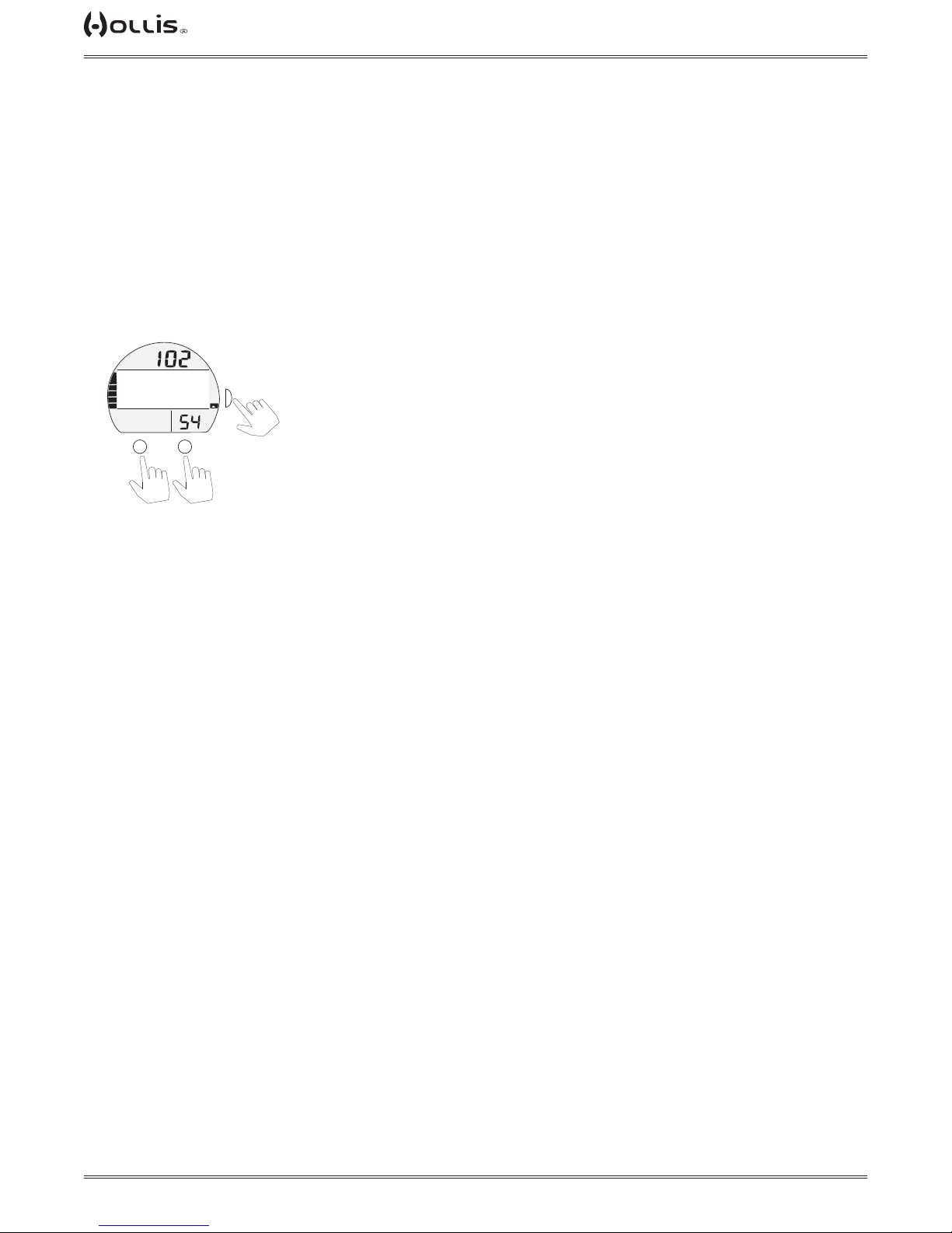
TX1 He OPERATING MANUAL
TAP
TAP
TAP
Deco Stops
Deco Stops is a menu that displays all of the currently required decompression stops, times, and the gases to be
used.
Information includes:
> Current Depth with FT or M icon.
> PO2 value (x.xx ATA) with PO2 icon, replacing Pressure when option E is selected.
> TAT (Total Ascent Time).
> TLBG with icon, Inert Gas Loading.
> VARI, Ascent Rate.
> Graphic FEET (or METERS) (depth of deco stops), MIN (duration of deco stops, Max 99 min), and GAS (Gas
Names).
> Graphic list of Depths, Duration, and Gas Names (AIR, NX FO2, or TX FO2/FHe).
FTM
60 5 NX 50
50 5 NX 50
40 6 NX 50
30 7 NX 50
TLBG
PO2
BAR
M
or
>
S
>
VARI
TAT
min
A
to select
downup
to scroll cursor (>)
Batt/TMT
Similar to the Surface Batt/TMT Menu (p.21).
© 2002 DESIGN (2014)
50
Doc. 12-4101-r06 (1/21/14)
Page 51

TX1 He OPERATING MANUAL
GAUGE
OP MODE
© 2002 DESIGN (2014)
51
Doc. 12-4101-r06 (1/21/14)
Page 52

TX1 He OPERATING MANUAL
TAP
TAP
TAP
TAP
GAUGE SURF SCREENS
Gauge Surf
Main
FTM
SURF
TMT1
PO2
BAR
PSI
M
DIVE 0
GTR
TAT
min
A
S
GAUGE
GAUGE SURF MAIN, information includes:
> SI (hr:min) with Time (clock) and SURF icons; if no dive yet, this is time since activation.
> Graphic GAUGE (operating mode).
> Graphic DIVE and number of dives completed during that operating period, up to 24 (0 if no dive made yet).
> Graphic TMT 1, default on surface before rst dive and 10 minutes after surfacing from dives.
> Tank Pressure with PSI (or BAR) and Link (speaker) icons, if the Receiver is successfully Linked with an active
TMT (Transmitter), 000 ashing after 15 seconds of lost Link.
> Battery icon, if voltage is low.
GAUGE SURF ALT 1, information includes:
> SI* (hr:min) with Time (clock) and SURF icons.
> Max Depth* with graphics FT (or M) and MAX.
> Elapsed Dive Time* (hr:min) with graphic EDT.
> Graphic LAST, indicating that data is from the dive previously conducted while in GAUGE mode.
FT MAX
TLBG
Gauge Surf
Alt 1
(PZ+)
EDT
83
232
PO2
BAR
PSI
M
Gauge Surf
Alt 2
FTM
SURF
S
GTR
TAT
min
A
(PZ+)
CF
12:45
TLBG
PO2
BAR
PSI
M
FTM
A
S
GTR
TAT
min
A
CF
FT
TLBG
Gauge Surf
Alt 3
(PZ+)
EDT
01:23
232
PO2
BAR
PSI
M
FTM
S
GTR
TAT
min
A
back to main
GAUGE SURF ALT 2, information includes:
> Altitude graphic, if EL - 2 (to EL - 7), blank if Sea level.
> Time of Day (hr:min) with graphic A (or P).
> Temperature with ° icon and graphic F (or C).
GAUGE SURF ALT 3, information includes:
> Graphics GAUG and AVE (average).
> Average Depth* with graphic FT (or M).
> Average EDT* (min) with graphic.
*These are average values calculated for the dive, or series of repetitive dives, conducted while still in
GAUGE.
© 2002 DESIGN (2014)
52
Doc. 12-4101-r06 (1/21/14)
Page 53
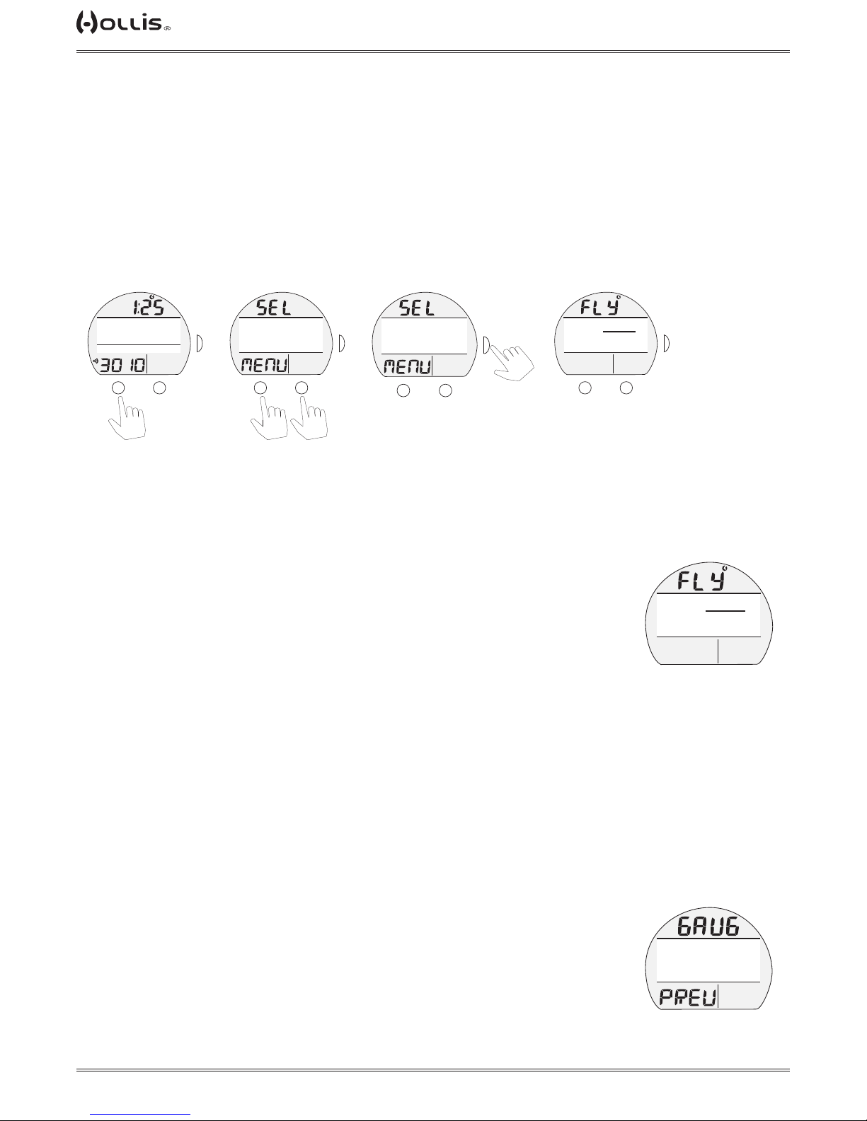
GAUGE MAIN MENU
TAP
TAP
TAP
TAP
Selections include:
> SWITCH TMT
> FLY.
> LOG.
> SET MENU.
> OP MODE.
> HISTORY.
> TX1 HE ID.
> BATT/TMT
> DIVE PREVIEW
TX1 He OPERATING MANUAL
Gauge Surf
Main
TMT1
PO2
BAR
PSI
M
DIVE 0
GAUGE
FTM
SURF
S
GTR
TAT
min
A
Gauge Surf
Main Menu
(PZ+)
CF
>FLY
LOG
SET MENU
OP MODE
TLBG
PO2
BAR
PSI
M
or
Gauge Surf
Gauge Fly
Main Menu
FTM
SURF
S
>
GTR
TAT
min
A
(PZ+)
CF
>FLY
LOG
SET MENU
OP MODE
TLBG
PO2
BAR
PSI
M
A
FTM
SURF
>
S
GTR
TAT
min
(PZ+)
CF
TLBG
PO2
BAR
M
downup
SWITCH TMT
The Switch TMT Menu selection provides access to a listing of sub menus that allow
the changing of the current TMT.
These Switch TMT Sub Menus are described after the Gauge Main Menu items (starting on
page 54).
FLY, information includes:
> Graphic FLY with countdown time (hr:min) and Time (clock) icon, dashes if no dive
yet.
LOG, shared with NORM (see page 21).
SET MENU, similar to NORM (see page 22).
> GAUGE does not access the Set Gases Menu.
FTM
SURF
23:50
PSI
GTR
TAT
min
A
TLBG
S
(PZ+)
FTM
CF
SURF
23:50
PO2
BAR
PSI
Fly
(10 min. after dive)
GTR
TAT
min
OP MODE, similar to NORM (see page 22).
HISTORY, shared with NORM (see page 23).
TX1 ID, same as NORM (see page 23).
BATT/TMT STATUS, same as NORM (see page 23).
DIVE PREVIEW
This feature provides quick access to a screen that displays up to 4 settings that can
be pre selected* using the Set P Menu.
Preview, information includes:
> Graphics GAUG and PREV.
> Selections* with Set Points entered using that menu.
• Press S button to revert to the Main Menu.
© 2002 DESIGN (2014)
53
(PZ+)
FTM
CF
DEPTH AL
EDT AL
TP AL
TMT1
TLBG
PO2
BAR
SURF
140 FT
60 MIN
300 PSI
ON
PSI
GTR
TAT
min
Gauge Dive
Preview
Doc. 12-4101-r06 (1/21/14)
Page 54
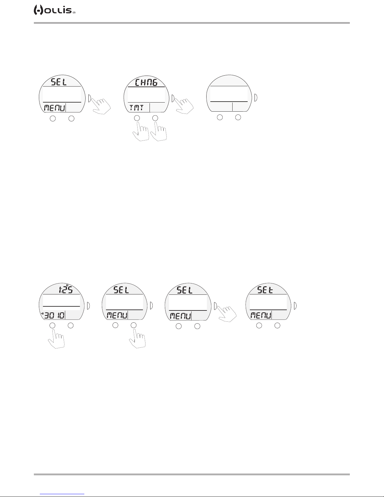
TX1 He OPERATING MANUAL
TAP
TAP
TAP
TAP
TAP
TAP
TAP
SWITCH TMT SUB MENUS
Information that follows describes the sub menus (GAUGE TMT SWITCH, TMT
SWITCH CONFIRMATION, SEARCHING TMT) that are accessed from the Gauge
SURF Main Menu.
Gauge Surf
Gauge TMT Switch Menu
Main Menu
(PZ+)
(PZ+)
FTM
FTM
SURF
CF
CF
>TMT SWITCH
>FLY
FLY
LOG
LOG
SET MENU
SET MENU
OP MODE
TLBG
TLBG
PO2
PO2
M
SURF
BAR
BAR
PSI
PSI
A
>
>
S
GTR
GTR
TAT
TAT
min
min
(PZ+)
(PZ+)
CF
CF
>USE DEFAULT
>TMT 2
TMT 3
ADD MAX D
TLBG
TLBG
PO2
PO2
BAR
BAR
M
PSI
PSI
A
or
to scroll cursor (>)
GAUGE TMT SWITCH, information includes*:
> Graphic CHNG and TMT
selections include:
> all active TMTS displayed as TMT #
FTM
FTM
SURF
SURF
S
GTR
GTR
TAT
TAT
min
min
to select
downup
Searching for TMT
(PZ+)
FTM
FTM
SURF
23:50
TMT 2
BAR
PSI
SURF
S
GTR
GTR
TAT
TAT
min
min
A
CF
CF
SEARCHING FOR ---
TLBG
PO2
M
* If there are no active TMTs then the TMT Switch Menu is unavailable.
** The current TMT and TMTs turned OFF will not display as options on the menu.
SEARCHING FOR TMT, information includes:
> Graphic SEARCHING FOR --- TMT (1, 2, 3, 4, 5, or 6).
SET GROUPS
Information that follows describes the selections contained in the GAUGE Set Groups
(A, U, T, S, D, P) that are accessed from the Set Menu.
Gauge Surf Main Sel Menu Sel Menu
(set menu highlighted)
TMT1
PO2
BAR
PSI
M
DIVE 0
GAUGE
(PZ+)
FTM
SURF
S
GTR
TAT
min
A
CF
>FLY
LOG
SET MENU
OP MODE
TLBG
PO2
M
FTM
SURF
S
BAR
>
PSI
GTR
TAT
min
A
(PZ+)
CF
FLY
LOG
>SET MENU
OP MODE
TLBG
PO2
BAR
PSI
M
A
FTM
SURF
x 2
S
>
GTR
TAT
min
Set Menu
(PZ+)
CF
>A-ALARMS
U-UTILITIES
T-TIME
S-SHORTCUT
TLBG
PO2
BAR
PSI
M
SET A (ALARMS), shared with NORM (see page 28).
SET U (UTILITIES), shared with NORM (see page 29).
> GAUGE includes TO SET TMT MENU similar to NORM Set TMT Menu (see page
27).
FTM
SURF
S
>
GTR
TAT
min
A
SET T (TIME/DATE), shared with NORM (see page 31).
© 2002 DESIGN (2014)
54
Doc. 12-4101-r06 (1/21/14)
Page 55
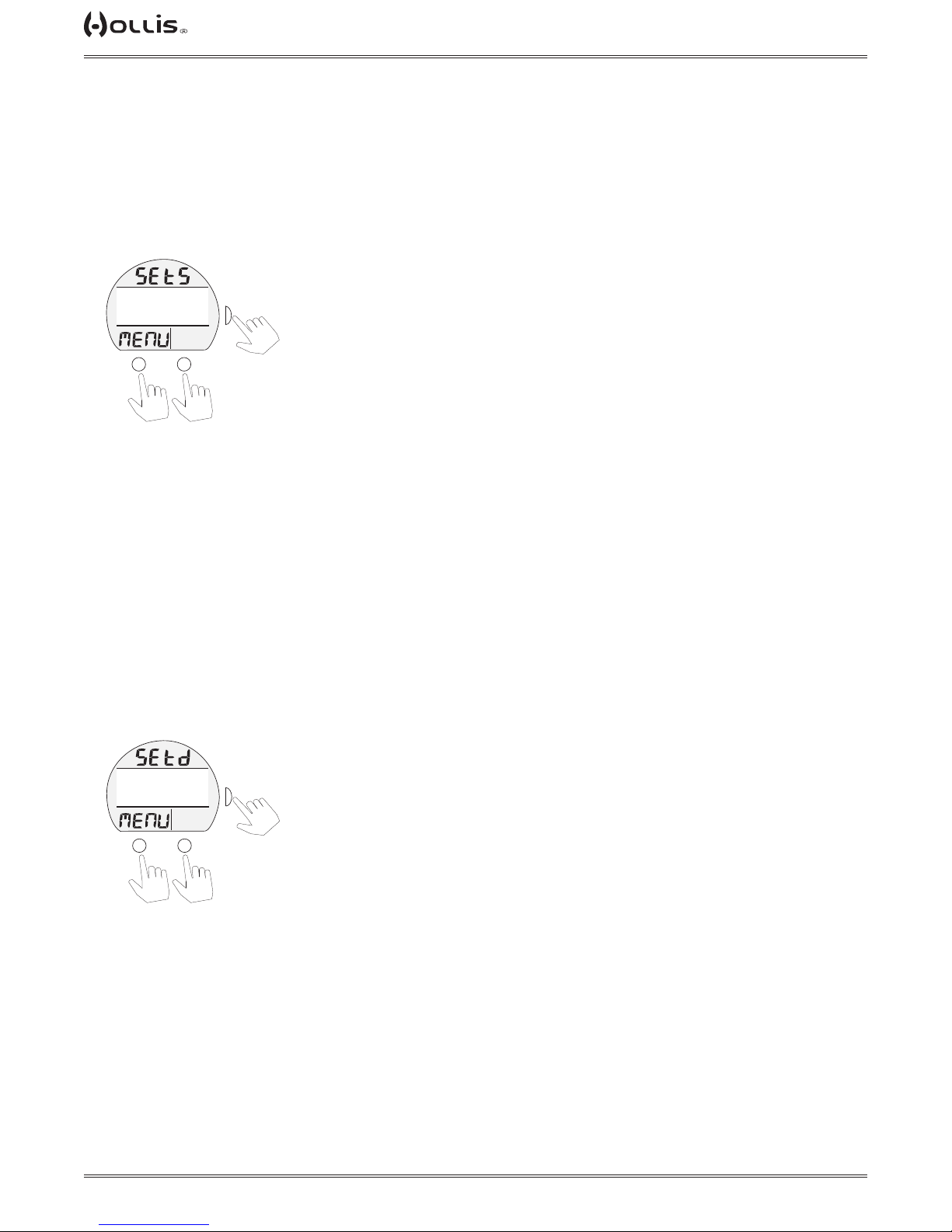
TX1 He OPERATING MANUAL
TAP
TAP
TAP
TAP
TAP
TAP
SET S (Shortcut) Menu, information includes:
> Graphics SEt S and MENU.
Selections include:
> LOG MENU.
> MY INFO (default Shortcut until another item is selected)
> SET HEADING.
> SET TIME.
Gauge Set S Menu
(PZ+)
FTM
CF
>LOG MENU
MY INFO
SET HEADING
SET TIME
TLBG
PO2
M
to scroll cursor (>)
One item can be selected from the list. That item (referred to as a Shortcut) can then be accessed directly by pressing M (2 sec.) while viewing the
Surface Main.
SURF
BAR
PSI
or
S
GTR
TAT
min
A
to select
downup
SET D (Dive Main) Menu, information includes:
> Graphics SEt d and MENU.
The default screen for dives displays Current Depth, Run Timer, Pressure, and GTR
(gas time remaining). Max Depth is displayed on an Alternate screen. Set D allows it
to be added to the Main (moving it from the Alternate).
Selections include:
> USE DEFAULT >> no change to the display.
> ADD MAX D >> also reduces the size of NDC digits.
Gauge Set D Menu
(PZ+)
FTM
CF
>USE DEFAULT
ADD MAX D
TLBG
PO2
M
to scroll cursor (>)
*Ensure that the selection to be saved reects information you want to see on the Dive Main, it
cannot be changed during the dive (only while on the surface using this menu).
SURF
BAR
PSI
or
S
GTR
TAT
min
A
to select
downup
© 2002 DESIGN (2014)
55
Doc. 12-4101-r06 (1/21/14)
Page 56
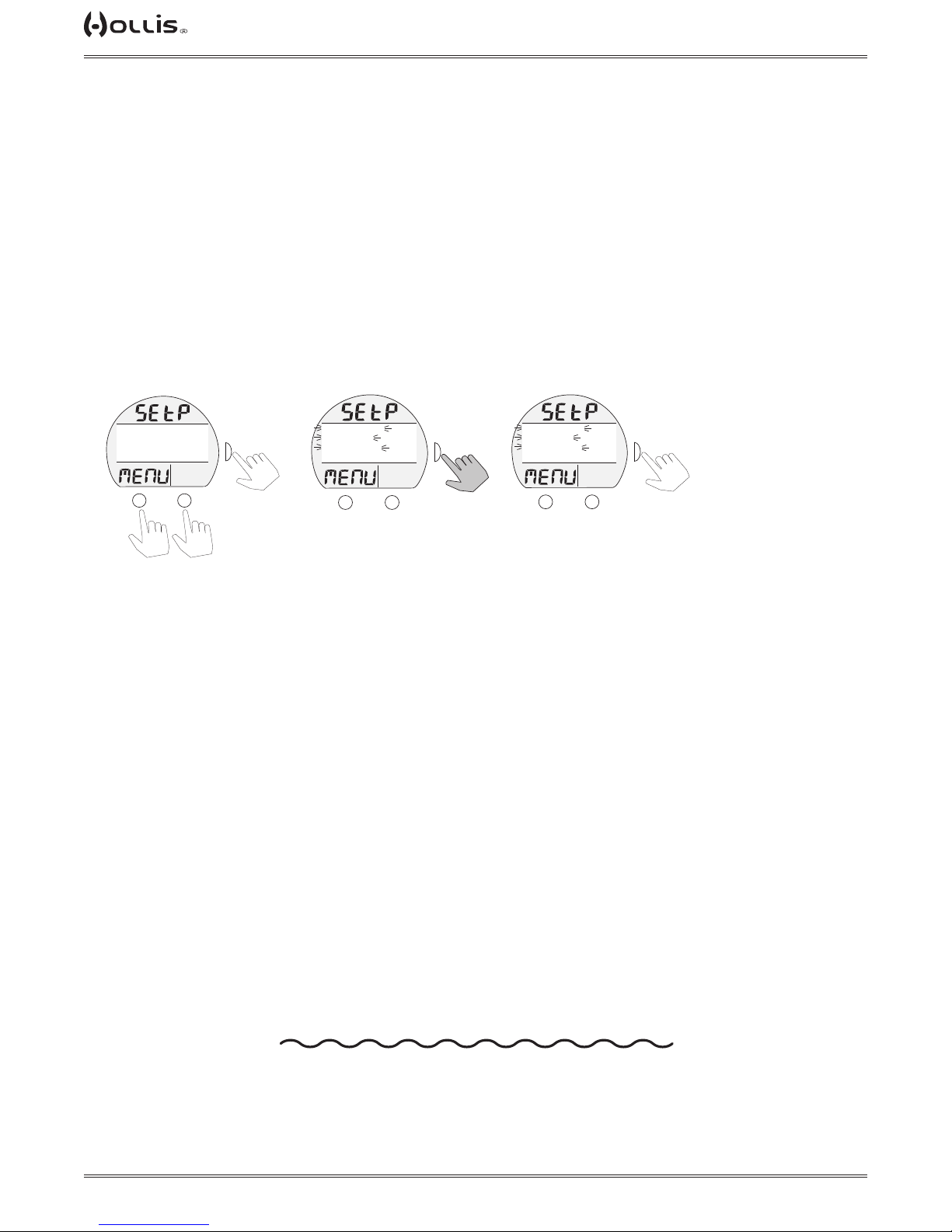
TX1 He OPERATING MANUAL
TAP
TAP
TAP
TAP
SET P (Preview) Menu, information includes:
> Graphics SEt P and MENU.
Using this menu, you can chose up to 4 items (Set Points that have been entered) for display on a Preview screen that can be
accessed from the
Surface Main Menu.
Selections include:
> DEPTH AL SET.
> EDT AL SET.
> TP AL SET.
> GLO DUR SET.
> MAX DEPTH
> TMT1 SET
> TMT2 SET
> TMT3 SET
> TMT4 SET
> TMT5 SET
> TMT6 SET
Guage Set P Menu
(PZ+)
FTM
CF
DEPTH AL SET
EDT AL SET
TP AL SET
>GLO DUR SET
TLBG
PO2
M
SURF
BAR
>
PSI
GTR
TAT
min
A
or
to scroll cursor (>)
S
to select
or deselect
downup
Guage Set P Menu
(selected items ash)
(PZ+)
FTM
CF
>DEPTH AL SET
>EDT AL SET
>GLO DUR SET
TLBG
PO2
M
SURF
BAR
>
PSI
GTR
TAT
min
A
S
to save
Guage Set P Preview
(only selected items display)
(PZ+)
FTM
CF
>DEPTH AL SET
>EDT AL SET
>GLO DUR SET
TLBG
PO2
M
SURF
S
BAR
>
PSI
GTR
TAT
min
A
to Set Menu
*Once 4 items are ashing, another item cannot be toggled to ash until one of the ashing items is toggled to solid.
When satised that those items ashing (up to 4) are what you want for the Preview screen, press S (2 sec) to display all items
ashing, then press S (< 2 sec) to revert to the Preview screen with all items solid.
Upon descent to 5 FT (1.5 M) for 5 seconds, operation
© 2002 DESIGN (2014)
will enter GAUGE Dive Mode.
56
Doc. 12-4101-r06 (1/21/14)
Page 57
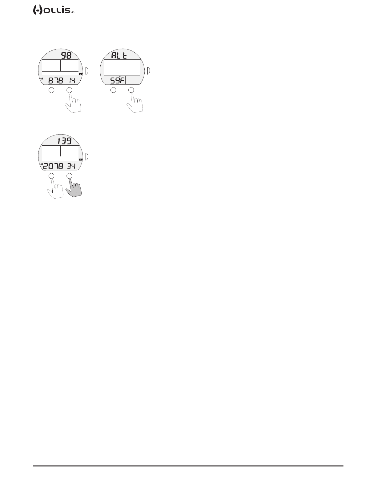
GAUGE DIVE SCREENS
TAP
TAP
TAP
Gauge Dive Main
(optional main, no timer)
TX1 He OPERATING MANUAL
Gauge Dive Alt
(timer not on)
(using timer, default main)
start/stop time
GAUGE DIVE MAIN, information** includes -
**Which information is displayed on the Main screen and which is on the Alternates is determined by the SET D menu selection saved during setup on the surface prior to the dive.
FTM
FT MAX
EDT
43
276
TMT1
PO2
BAR
M
GTR
PSI
A
Gauge Dive Main
FTM
TIME
EDT
6
2:46
TMT1
PO2
BAR
M
GTR
PSI
A
or
HOLD
VARI
TAT
min
VARI
TAT
min
reset time
FTM
SURF
S
10:55
PO2
M
A
BAR
S
GTR
TAT
min
A
back to main
S
> Current Depth with FT (or M) icon.
> Graphic TIMER with Time (up to 999:59 min:sec), 0:00 until started and after reset.
> Max Depth with graphics FT (or M) and MAX, if set for display.
> Graphic EDT with Elapsed Dive Time (up to 999 min).
> Graphic TMT (1, 2, 3, 4, 5, or 6), one in use.
> Pressure (or letters SPG if no tmt) with PSI (or BAR) and Link icons, if Rcvr and
TMT are active, ashing when Link is lost.
> GTR (up to 199 min) with GTR and min icons, dashes ( - - ) if on the surface.
> VARI while ascending.
• A (< 2 sec) to access ALT.
• A (2 sec) to Reset Run Timer (to 0:00).
• A (< 2 sec) to Start/Stop the Timer.
• M (2 sec) to access TMT Switching*.
• S (< 2 sec) to activate Smartglo® Backlight or acknowledge alarms.
• S (2 sec) to access Compass*.
*These items can only be accessed while viewing the Main.
GAUGE DIVE ALT, information includes > Graphic ALt.
> Max Depth with MAX and FT (or M) icons, if Timer is on Main.
> Time of Day (hr:min) with graphic A (or P) if 12 Hour.
> Temperature with ° icon and graphic F (or C).
• A (< 2 sec) to revert to Main.
• Revert to Main in 5 sec, if A is not pressed.
• S (< 2 sec) to activate Smartglo® Backlight.
© 2002 DESIGN (2014)
57
Doc. 12-4101-r06 (1/21/14)
Page 58
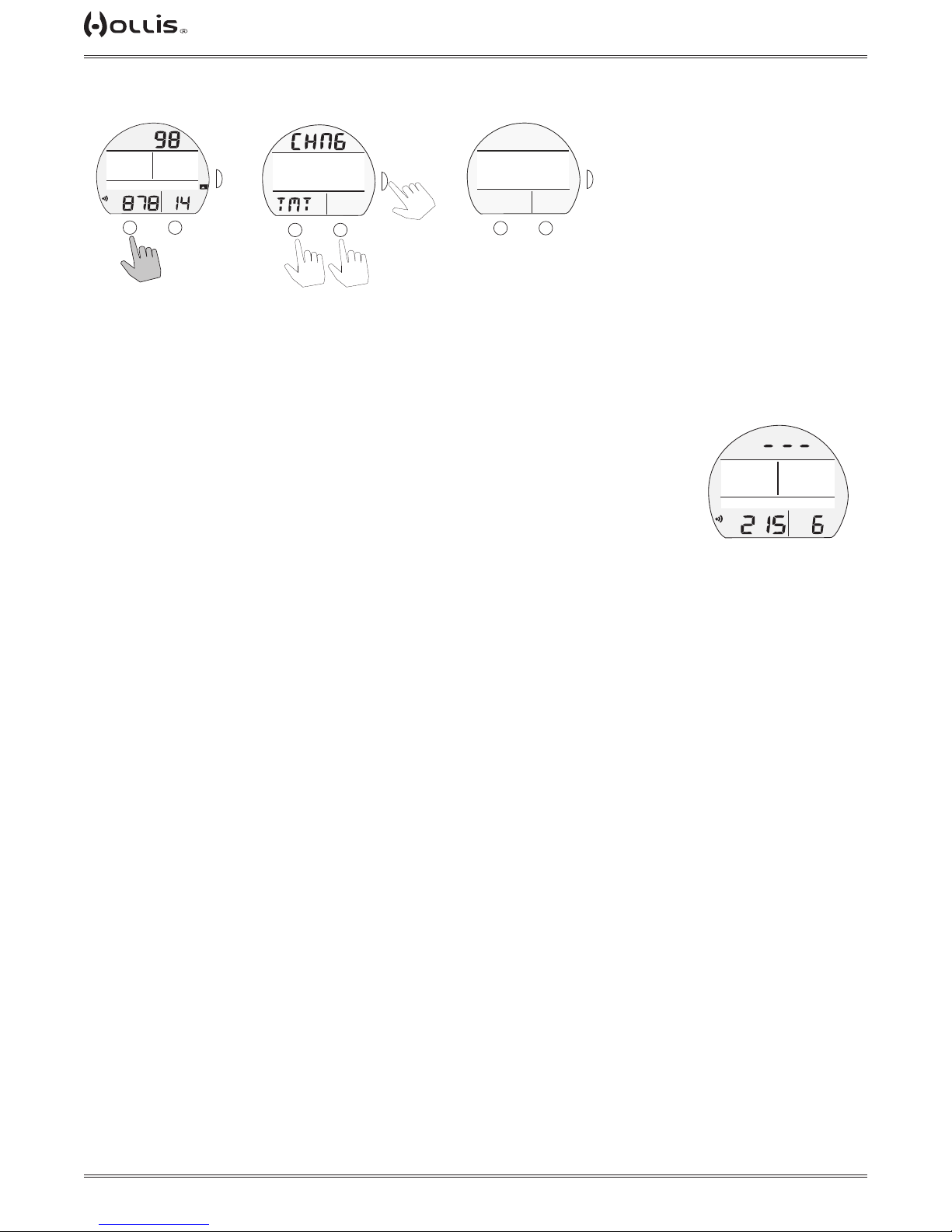
TX1 He OPERATING MANUAL
TAP
TAP
TAP
GAUGE DIVE CHANGE TMT SCREENS
Gauge Dive Main
Gauge TMT Switch Menu
(optional main, no timer)
(PZ+)
(PZ+)
CF
CF
>USE DEFAULT
>TMT 2
TMT 3
ADD MAX D
TLBG
TLBG
PO2
PO2
BAR
BAR
M
FTM
FTM
SURF
SURF
PSI
PSI
or
S
GTR
GTR
TAT
TAT
min
min
A
to select
FT MAX
276
TMT1
PO2
M
EDT
BAR
PSI
FTM
43
VARI
GTR
TAT
min
A
S
downup
to scroll cursor (>)
GAUGE TMT SWITCH, shared with GAUGE SURF MODE (see page 54).
SEARCHING FOR TMT, shared with GAUGE SURF MODE (see page 54).
GAUGE DEPTH VIOLATION
Upon descent deeper than the Max Functional Depth of 400 FT/120 M, the Audible
will sound during which the alarm LED will ash.
Current Depth and Max Depth (if no timer on Main) will only indicate 3 dashes
( - - - ) signifying that you are Out of Range.
Upon ascending above the Max Functional Depth, Current Depth will be restored,
however, Max Depth (if no timer on Main) will display 3 dashes for the remainder of
that dive. Also, the Log for that dive will display 3 dashes as the Max Depth.
Searching for TMT
(PZ+)
FTM
FTM
SURF
23:50
TMT 2
BAR
PSI
SURF
S
GTR
GTR
TAT
TAT
min
min
A
CF
CF
SEARCHING FOR ---
TLBG
PO2
M
FTM
TIME
EDT
BAR
PSI
16
GTR
TAT
min
12:46
TMT1
PO2
Gauge Depth Violation
© 2002 DESIGN (2014)
58
Doc. 12-4101-r06 (1/21/14)
Page 59

TX1 He OPERATING MANUAL
COMPASS
MODE
© 2002 DESIGN (2014)
59
Doc. 12-4101-r06 (1/21/14)
Page 60
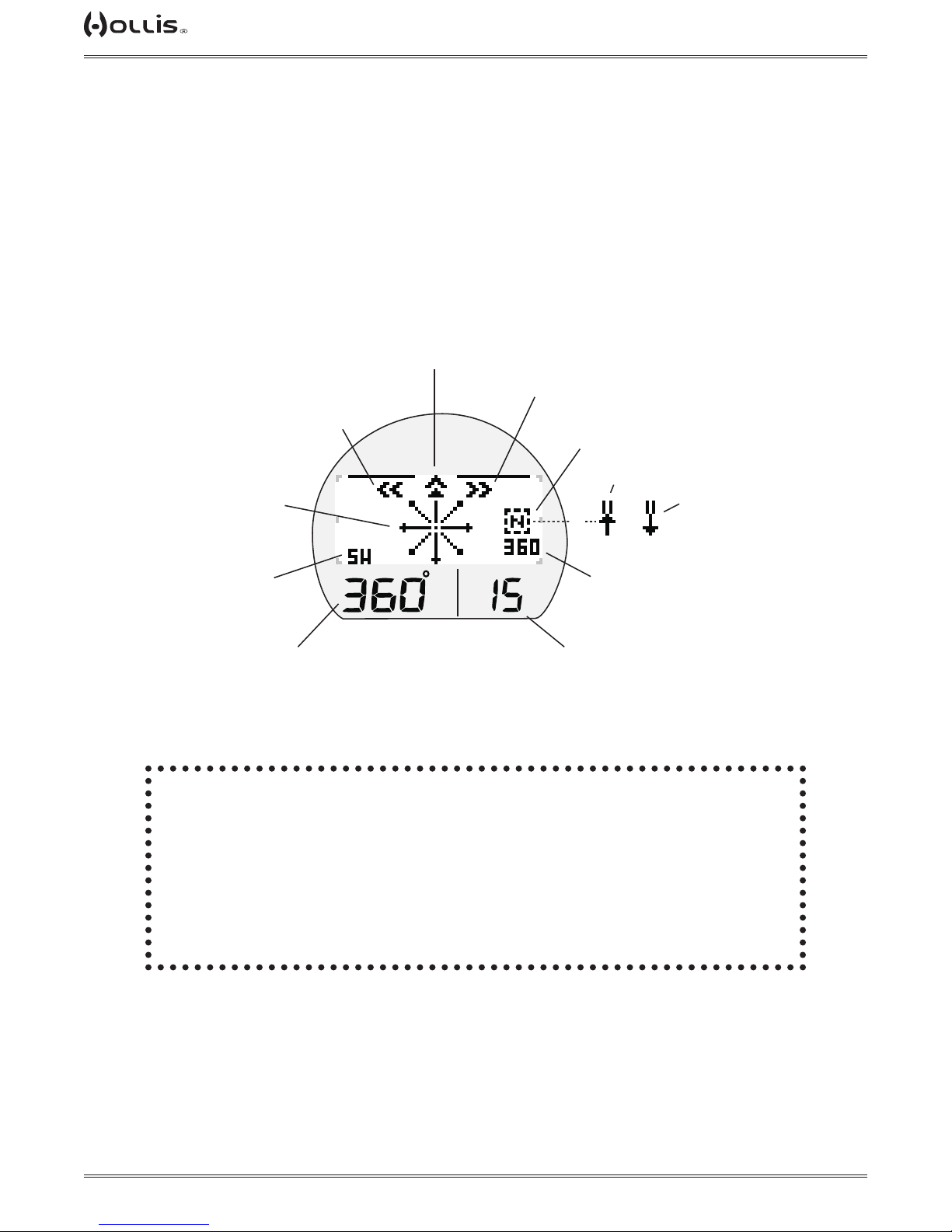
Dynamic North, or
RefHeading set
TX1 He OPERATING MANUAL
Diver’s
Direction of
Travel
Turn Right
Turn Left
North OP Mode
Reference OP Mode
Ref Reverse
or
Diver’s general
direction
Diver’s actual
Heading
TLBG
PO2
BAR
Ref Heading set
Compass Access Time remaining
when <= 15 sec.
(press S button to extend time)
! WARNING: You must become thoroughly familiar with setup and
operation of the TX1 He Digital Compass before using it as your
primary device for navigation. Failure to do so could result in serious errors relating to activities involving navigation.
> Practice on land before use in water.
> Practice on the surface before use underwater.
© 2002 DESIGN (2014)
60
Doc. 12-4101-r06 (1/21/14)
Page 61
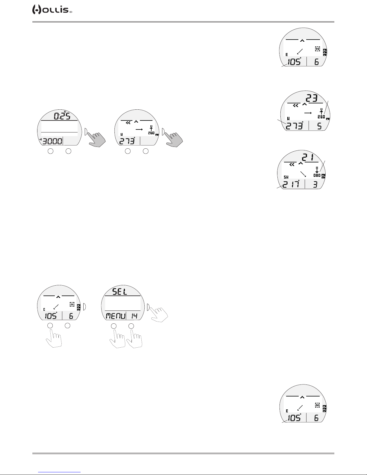
TX1 He OPERATING MANUAL
heading
heading
TAP
TAP
TAP
TAP
heading
OVERVIEW
> Compass OP Mode selected (North or Reference) - remains until changed.
> Reference OP Mode - can set a course, then also select a Reverse course while on
the surface and during dives.
> Numeric values are displayed as 3 digits (000 to 360°), have a resolution of 001°,
and an accuracy of +/- 005°.
> Operation will be normal and display of values will be within specied tolerances up
to 90° tilt at which time the Heading
(diver's direction) digits are removed until the tilt angle is corrected.
From Surf Main or Dive Main Compass Main
(North OP Mode)
TLBG
PO2
BAR
actual
NORTH OP MODE
VARI
course
FT
set
FTM
SURF
PO2
M
BAR
PSI
DIVE 0
GAS1
GTR
TAT
min
A
S
HOLD
TLBG
PO2
BAR
M
S
VARI
HOLD
A
or no button
press for
NORM
aır
2 min* to return
to main screen
*During the nal 15 seconds, the remaining On time is displayed in the lower right corner.
If a button is pressed during that time, the 2 minute On time will reset allowing operation to
remain in Compass Mode.
Upon accessing the Compass, the OP (operating) Main of the last mode selected will
be displayed >> North, Reference, or Reverse Reference.
COMPASS MENU
Selections include:
> NORTH MODE -select as OP Mode with no set heading.
> REF MODE - select as OP Mode with set heading allowed.
> CALIBRATE - access to initiate Calibration.
> SET DECLINATION - access to set Declination.
Compass Main Compass Menu
actual
heading
TLBG
PO2
BAR
REF OP MODE
FT
TLBG
PO2
BAR
actual
REVERSE REF OP MODE
180°
opposite
set
VARI
VARI
>NORTH MODE
REF MODE
S
TLBG
PO2
BAR
M
VARI
A
CALIBRATE
SET DECLIN
PO2
BAR
M
or
to scroll cursor (>)
NOTE: Compass Menu is only available while in Surface Mode.
NORTH OP MAIN, information includes -
> Current Depth with FT (or M) icon, Surface Interval during rst 10 min on surface,
blank on surface > 10 min.
> North Mode icon (letter N in box).
> Static Arrow icon (at 12 o'clock), diver direction of travel.
> Dynamic Arrow, relative direction of magnetic North.
> Numeric heading (diver's current direction), 001 to 360°, with position graphic (N, E,
SE, etc.).
> On time remaining, counting down, if 15 to 0 (sec) remaining.
© 2002 DESIGN (2014)
S
A
to select
downup
VARI
actual
TLBG
PO2
BAR
NORTH OP MAIN
(at 105°)
61
Doc. 12-4101-r06 (1/21/14)
Page 62
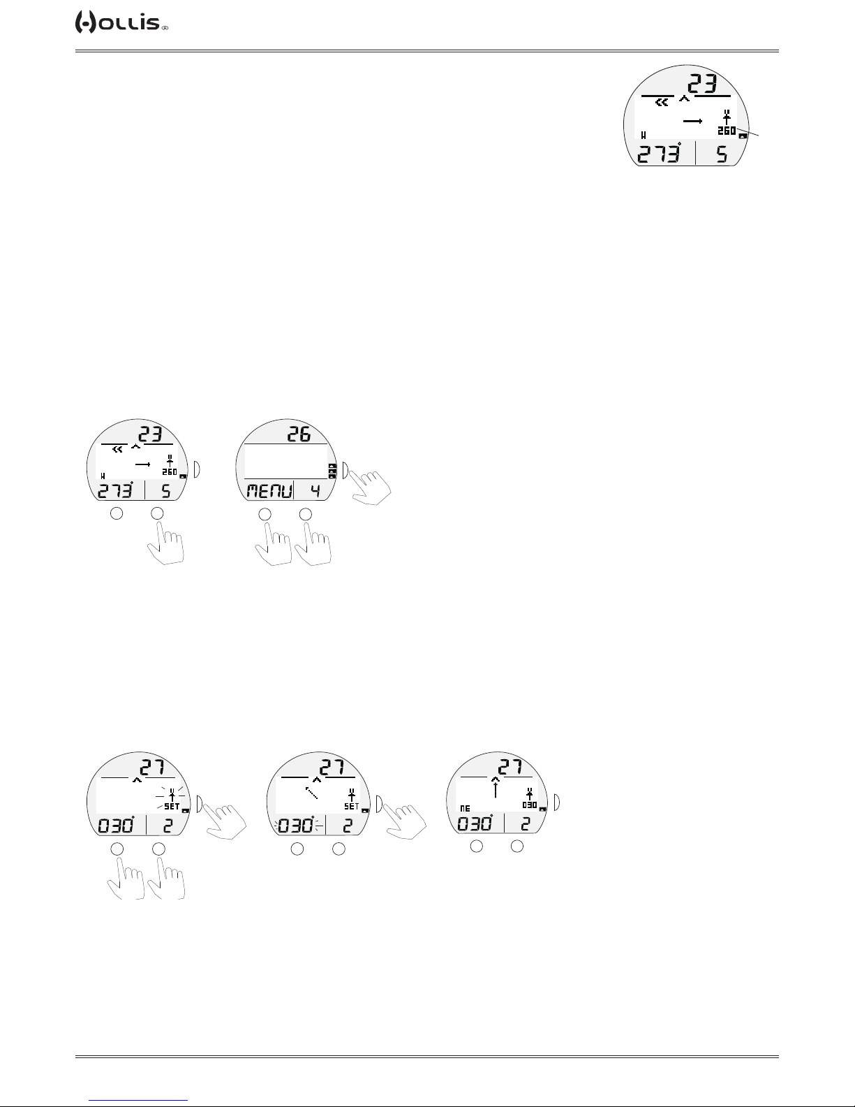
TX1 He OPERATING MANUAL
TAP
TAP
TAP
TAP
TAP
TAP
TAP
TAP
REFERENCE OP MAIN, information includes -
> Current Depth with FT (or M) icon, Surface Interval during rst 10 min on surface,
blank on surface > 10 min.
> Reference Mode icon (2 bars with arrow) with numeric Reference heading (course)
set below it.
> Static Arrow icon (at 12 o'clock), diver direction of travel.
> Turn Arrow icon (left or right) ashing during any time the diver deviates ≥ 10° off
the heading set.
> Dynamic Arrow, tracking Reference direction set.
> Numeric heading (diver's current direction), 001 to 360°, with position graphic (N, E,
SE, ESE, etc.).
> On time remaining, counting down, if 15 to 0 (sec) remaining.
REFERENCE MENU, information includes > Current Depth with FT (or M) icon, blank on surface.
> Graphic MENU, with selections ->
> SET HEADING.
> REVERSE HEADING.
> On time remaining, counting down, if 15 to 0 (sec) remaining.
REF OP Main
TLBG
PO2
BAR
FT
S
VARI
REF Menu
FT
>SET HEADING
REVERSE HEADING
PO2
BAR
S
VARI
FT
TLBG
PO2
BAR
REF OP MAIN
(at 277°, turn left to 260°)
a
VARI
A
M
A
M
or
to select
downup
to scroll cursor (>)
Set Reference Heading, information includes > Current Depth with FT (or M) icon, blank on surface.
> Reference Mode icon (2 bars with arrow) with graphic SET (ashing) below it.
> Static Arrow icon (at 12 o'clock), diver direction of travel.
> Dynamic Arrow, tracking Reference direction set.
> Numeric heading (diver's direction), with position graphic.
> On time remaining, counting down, if 15 to 0 (sec) remaining.
Rotate To Desired Heading
(while holding level)
FT
S
BAR
VARI
A
to Lock
Heading
TLBG
PO2
BAR
M
TLBG
to Compass
Menu
FT
S
PO2
BAR
M
VARI
A
to continue
TLBG
PO2
M
to Reference
Menu
FT
S
VARI
A
© 2002 DESIGN (2014)
62
Doc. 12-4101-r06 (1/21/14)
Page 63
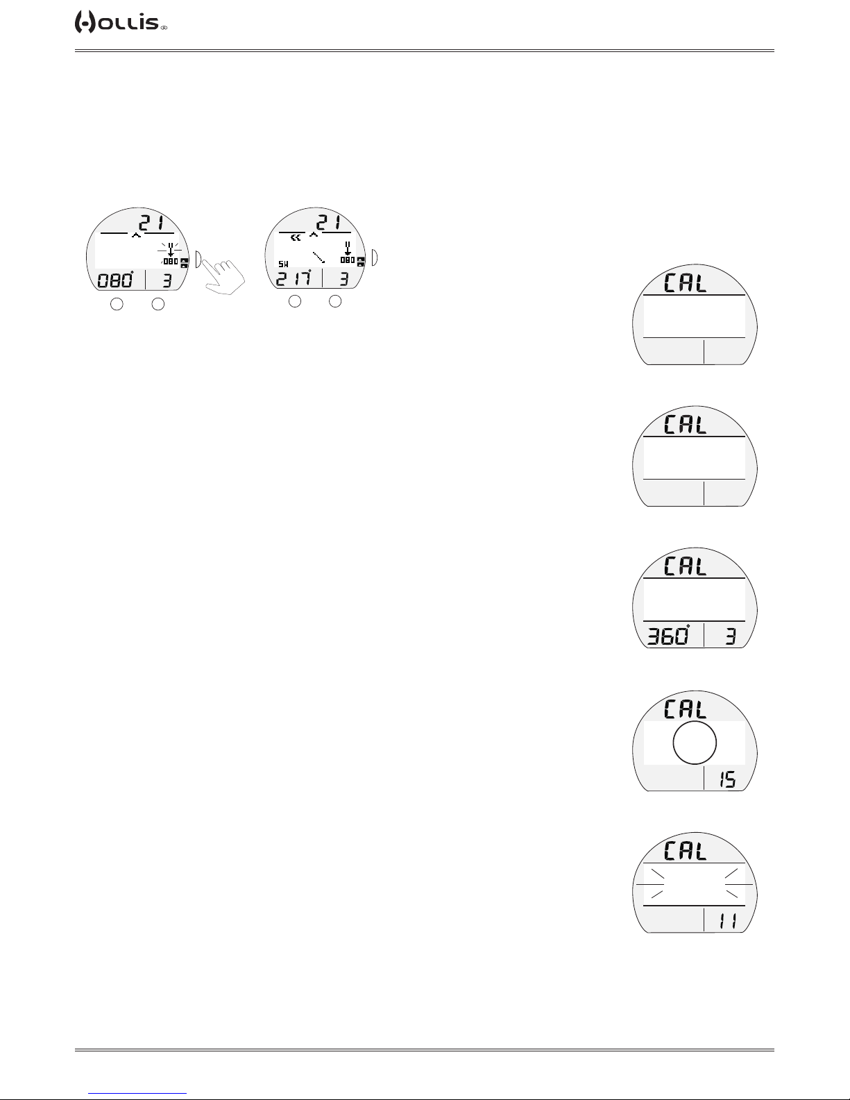
TX1 He OPERATING MANUAL
TAP
Reverse Ref Heading, information includes > Current Depth with FT (or M) icon, blank on surface.
> Reverse Mode icon (2 bars with arrow) with reverse Heading (180° opposite of
Reference Heading set) below it (ashing).
> Static Arrow icon (at 12 o'clock), diver direction of travel.
> Dynamic Arrow, tracking Reference direction set.
> Numeric heading (diver's direction), with position graphic.
> On time remaining, counting down, if 15 to 0 (sec).
FT
S
TLBG
PO2
BAR
M
VARI
A
to accept
Heading
TLBG
PO2
M
FT
S
BAR
VARI
A
The value below the Reverse Mode icon will stop ashing indicating the Heading has been
reversed.
CALIBRATION (surface only)
Local magnetic elds can effect display of actual location when reading a digital
compass.
It may be advantageous to Calibrate the Compass before its rst use after purchase,
before use in new global regions, or if inaccuracies are experienced.
Calibration will be required when the battery is changed.
Upon selecting Calibration on the Compass Menu (by S < 2 sec), a screen appears
displaying the graphics CAL with Face Down Until Beep*.
*This screen will also be accessed after the Battery is changed and Data is either saved or
cleared.
FACE DOWN
UNTIL BEEP
ACCES TO CAL
(turn unit upside down)
FACE DOWN
UNTIL BEEP
AFTER BEEP
(turn unit right side up)
ROTATE TO
CALIBRATE
To initiate Calibration > turn the unit over (face down) until it beeps, then > turn the unit over (face up) until it beeps, after which a screen appears displaying
the graphics CAL with Rotate To Calibrate 360°.
> while keeping it in a at level position, slowly and steadily rotate* it 360° while
keeping it in a at level position (keeping it level is critical for accuracy), progress will
be indicated by a circle forming on the display.
*Rotation should take about 15 seconds. If not fully rotated in 15 seconds, operation will revert
to the Compass Menu.
Calibration complete -
> Once fully formed, the circle will be replaced with the graphics Ready Passed Cali-
bration or Failed Calibrate Again, ashing for 3 seconds, then -
> If READY, operation reverts to the Compass OP Main.
> If FAILED, operation reverts to the CAL Face Down Until Beep screen for repeat of
the procedure.
> If Calibration fails 3 times, operation reverts to the Surface Main screen.
TO START CAL
CAL PROGRESS
(circle forms while rotating)
READY
PASSED
CALIBRATION
CAL PASSED
© 2002 DESIGN (2014)
63
Doc. 12-4101-r06 (1/21/14)
Page 64
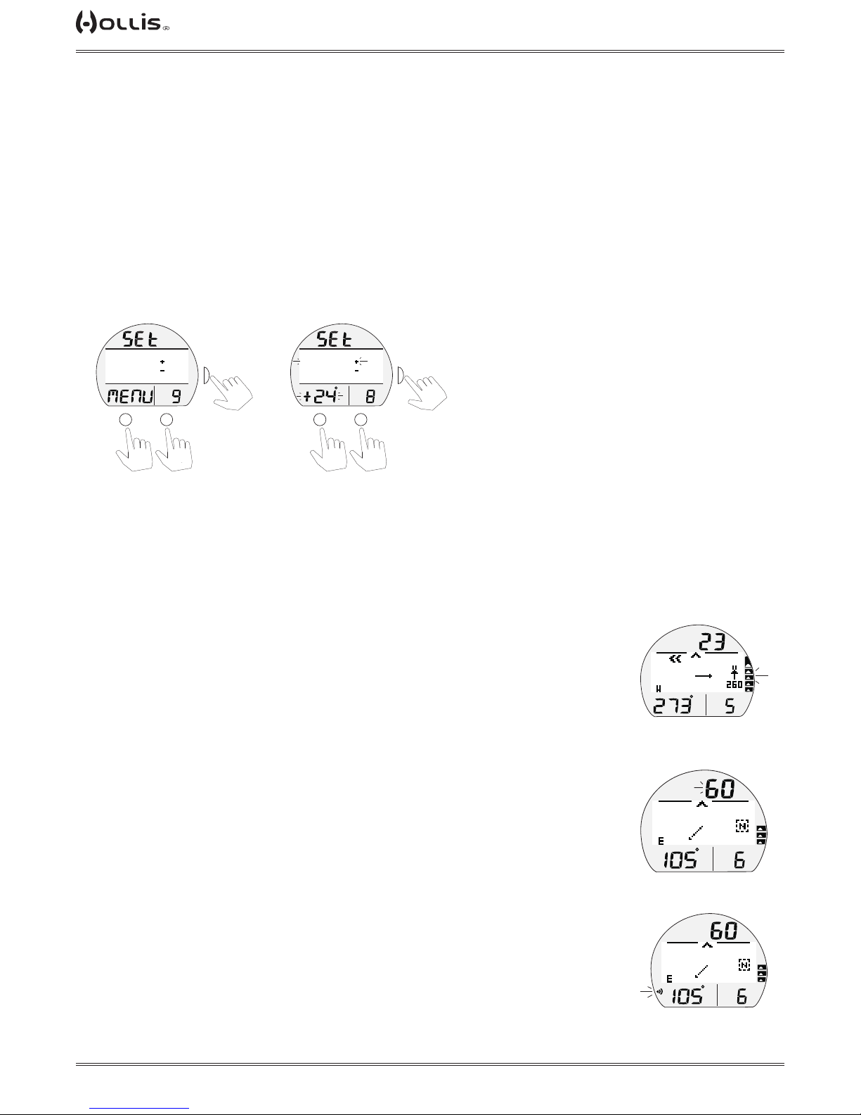
TX1 He OPERATING MANUAL
TAP
TAP
TAP
TAP
TAP
TAP
DECLINATION
Magnetic Declination is taken from numbers provided on maps or charts that apply to
a specic location. The numbers represent
the easterly or westerly angular difference (Declination) in degrees between magnetic
North and true (geometric or polar) North.
A Compass will point to magnetic North unless its reference is adjusted to true North
prior to conducting activities.
Declination Menu, information includes > Graphics SEt and MENU, with selections > OFF.
> DECLIN EAST + .
> DECLIN WEST - .
Declination Menu
Set Declination East or West
(declination east chosen, ashing)
>OFF
DECLIN EAST
DECLIN WEST
PO2
BAR
A
M
or
downup
to scroll cursor (>)
S
to select
OFF
>DECLIN EAST
DECLIN WEST
PO2
BAR
A
to save setting
+
or
M
-
to adjust setting
S
> If OFF is selected, Declination is set for 0° and operation reverts to the Compass
Menu.
> If DECLIN EAST (or WEST) is selected, that graphic will ash and the numeric
value with ° icon will ash in place of the
graphic MENU.
ALARMS
When most Alarms strike, operation in Compass Mode will be terminated and the
Dive Main will be displayed indicating the alarm condition. Compass Mode can then
be reentered by pressing S (2 sec).
During several types of alarms, indication will be given while remaining in Compass
Mode without interuption. They are -
Ascent Alarm -
> VARI, all segments ashing until slowed.
TLBG
PO2
BAR
ASCENT ALARM
FT
VARI
FT
Depth Alarm -
> Depth digits ashing until < alarm depth set.
Loss of Link -
> Link icon on ashing until Link is regained.
© 2002 DESIGN (2014)
64
TLBG
PO2
BAR
VARI
DEPTH ALARM
FT
TLBG
PO2
BAR
VARI
LOSS OF LINK
Doc. 12-4101-r06 (1/21/14)
Page 65

TX1 He OPERATING MANUAL
REFERENCE
CAUTION: When the procedure provided in this section is used to change
the TX1 He battery, you must be sure that the case O-ring is not pinched
and that the TX1 He is water tight before conducting diving activities.
Pre-dive pressure testing by an Authorized Hollis Facility is highly recommended.
© 2002 DESIGN (2014)
65
Doc. 12-4101-r06 (1/21/14)
Page 66
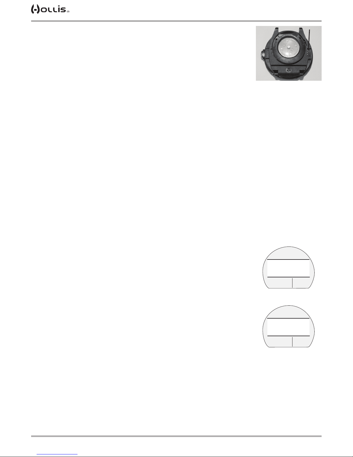
TX1 He OPERATING MANUAL
a
PC INTERFACE
The TX1 He is congured with a Data Port that enables it to be connected to a PC
through a USB port using a special
Interface Cable supplied or available as an optional accessory.
A USB Driver is provided on the HCI CD. This must be installed on the PC with the
program.
The Settings Upload feature can be used to set/change all of the unit's settings except FO2 and FHe which must be entered using the unit's control buttons and menu
system.
Information* available for retrieval (Download) from the TX1 He to the PC HCI program includes items such as dive number, surface interval time, max depth, elapsed
dive time, start date and time, lowest temperature underwater, sampling rate, dive
prole, Set Points, start/end pressure, Gas Time Remaining, O2 data, ascent rate,
TLBG, and Switching events.
The TX1 He checks for the presence of an interface device connection to the Data
Port once every second while in Surface Mode. Checks are not made if the Wet Activation contacts are wet.
Upon sensing an interface connection, the requesting device (PC) connects to the
TX1 He and is prepared for Upload of settings or Download of data which is then initiated using the PC HCI program.
Prior to attempting to Download data from your TX1 He or Upload settings to it, review the Help section of the HCI program. Recommended is to print those sections of
Help that you consider appropriate for your interface activities.
The TX1 He checks for a connection to the Data Port once every second while the
Surface Main is displayed. Checks are not made if the Wet Activation contacts are
wet.
When the PC Interface cable is plugged in, the graphic PC COMM is displayed with a
2 minute countdown timer that runs until the connection is conrmed, then the graphics PC COMM CONNECTED are displayed until completion of the upload or download operation.
PC REQUIREMENTS:
• IBM®, or compatible, PC with USB Port
• Intel® Pentium 200 MHz or better microprocessor
• Microsoft® Windows® 2000, XP, Vista, or 7
• Super VGA card or compatible video graphics adaptor (256 color or greater) with a
minimum 800 X 600 pixel screen area of display settings
• 16MB of available RAM
• 20MB of available hard drive storage
• Mouse
• CD ROM drive
• Printer
For software updates, refer to the Hollis web site at ->> www.HollisGEAR.com
For support, call Hollis Support toll free at ->> (510)729-5110, 8 AM TO 5 PM USA
Pacic time.
TX1 He
(a - data port)
FTM
CF
PC COMM
120 SECONDS
PCI CABLE
(connected)
CF
PC COMM
CONNECTED
PCI CONNECTION
(conrmed)
SURF
SURF
GTR
TAT
min
GTR
TAT
min
© 2002 DESIGN (2014)
66
Doc. 12-4101-r06 (1/21/14)
Page 67

TX1 He OPERATING MANUAL
b
CARE AND CLEANING
Protect your unit from shock, excessive temperatures, exposure to chemicals, and
tampering. Protect the lens against scratches with a Instrument Lens Protector. Small
scratches will naturally disappear underwater.
• Soak and rinse the TX1 He in fresh water at the end of each day of diving, and
check to ensure that the areas around the low pressure (depth) sensor, PC interface
data port, and buttons are free of debris or obstructions. Soak and rinse the regulator
with the transmitter attached.
• To dissolve salt crystals, use lukewarm water or a slightly acidic bath (50% white
vinegar/50% fresh water). After removal from the bath, place the TX1 He and the
regulator assembly with transmitter under gently running water and towel dry before
storing.
• Transport your TX1 He system cool, dry, and protected.
INSPECTIONS AND SERVICE
Your TX1 He should be inspected annually by an Authorized Hollis Dealer who will
perform a factory prescribed function check and inspection for damage or wear. To
keep the 2 year limited warranty in effect, this inspection must be completed one year
after purchase (+/- 30 days).
Hollis recommends that you continue to have an inspection performed every year to
ensure it is working properly.
The costs of annual inspections, or inspections relating to water tight integrity, are not
covered under the terms of the 2 year limited warranty.
To Obtain Service:
Take your TX1 He to your local Authorized Hollis Dealer.
a
TX1 He
(a - depth sensor, b - data port)
If required to return your TX1 He to the Hollis USA factory:
• Obtain an RA (Return Authorization) number by contacting Hollis USA at (510)7295110 or send an e-mail to [email protected].
• Record all dive data in the Log and/or download the data stored in memory. All data
will be erased during factory service.
• Package it using a protective cushioning material.
• Include a legible note stating the specic reason for return, your name, address,
daytime phone number, serial number(s), and a copy of your original sales receipt
and Warranty Registration.
• Send freight prepaid and insured using a traceable method.
• Non-warranty service must be prepaid. COD is not accepted.
• Additional information is available on the Hollis web site HollisGear.com or on the
local Hollis web site that serves your global region.
© 2002 DESIGN (2014)
67
Doc. 12-4101-r06 (1/21/14)
Page 68
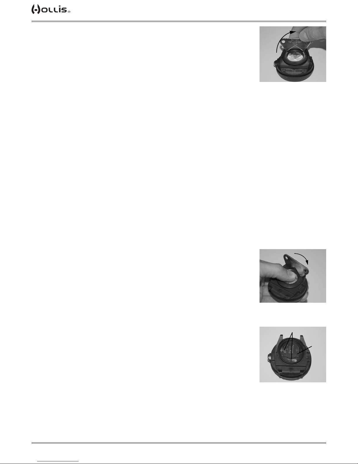
TX1 He OPERATING MANUAL
BATTERY REPLACEMENT
The procedures that follow must be closely adhered to avoid entrance of
water into the unit. Damage due to improper Battery replacement (or subsequent leakage of moisture into the unit) is not covered by the TX1 He's 2
year warranty.
When replacing the Battery in the TX1 He, it is recommended that you also consider
replacing the Battery(s) in the Transmitter(s) to be used, and vice-versa.
The Battery Compartment should only be opened in a dry and clean environment
with extreme care taken to prevent the entrance of moisture or dust.
As an additional precautionary measure to prevent formation of moisture in the
Battery Compartment, it is recommended that the Battery be changed in an environment equivalent to the local outdoor temperature and humidity (e.g., do not change
the Battery in an air conditioned environment then take it outside during a hot sunny
day).
Inspect the Buttons, Lens, and Housing to ensure they are not cracked or damaged.
If there is any sign of moisture inside the unit, DO NOT attempt to use it for diving
until it receives proper service by the Hollis factory or an Authorized Regional Facility.
OPEN
TX1 He
(cover removal)
Data Retention
When the battery is removed, settings* and calculations for repetitive dives are
retained in volatile memory until a new battery is installed. You will have the choice of
saving or deleting the data (see page 70).
*Date will have to be set, Time may require adjustment for the time duration that the
battery remains out of the unit.
Battery Cover Removal
• Locate the Battery Compartment on the back of the module.
• While applying steady inward pressure on the clear Battery Cover, rotate the Cover
Ring clockwise 10 degrees (using a battery replacement tool).
• Lift the Cover Ring up and away from the Housing.
• Remove the clear Battery Cover.
Battery Removal
• Remove the Retaining Bar located across the lower portion of the Battery.
• Remove the Cover O-ring. DO NOT use tools.
• Using care not to damage the Battery Contacts, slide the Battery up and out of the
right side of the Battery Compartment.
DO NOT allow a metal object to short circuit the top of the Battery which is
positive (+) to the negative ( - ) contact of the Compartment.
OPEN
TX1 He RELEASE COVER
RING
b
a
© 2002 DESIGN (2014)
68
(a - retaining bar, b - contacts)
TX1 He
Doc. 12-4101-r06 (1/21/14)
Page 69
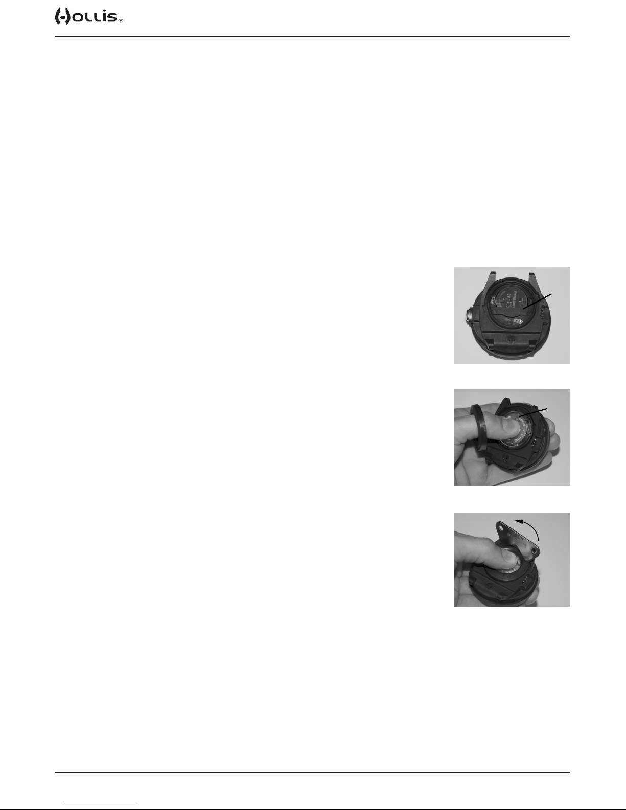
TX1 He OPERATING MANUAL
Inspection
• Closely check all of the sealing surfaces for any signs of damage that might impair
proper sealing.
• Inspect the Buttons, Lens, and Housing to ensure they are not cracked or damaged.
• Remove the Battery Cover O-ring and inspect it for any signs of deterioration or
deformity. DO NOT use tools to remove the O-ring.
• To ensure proper sealing, O-ring replacement is highly recommended each time the
Battery is replaced.
• Closely examine the Battery Cover and Housing for any signs of damage that might
prevent proper threading.
• Closely examine the inside of the Battery Compartment for any signs of corrosion
indicating entrance of moisture into the unit.
! WARNING: If damage, moisture, or corrosion is found, return your unit
to an Authorized Hollis Dealer, and DO NOT attempt to use it until it has
received factory prescribed service.
TX1 He Battery Installation
• Slide a new 3 volt CR2450 Lithium Battery, negative ( - ) side down into the cavity of
the battery compartment. Slide it in from the right side and ensure that it slides under
the contact clip on the left rim of the cavity.
• Orient the Retaining Bar across the lower portion of the Battery and carefully push it
down into position.
• Replace the Cover O-ring with a new one which must be a genuine Hollis part that
can be purchased from an Authorized Hollis Dealer.
a
Use of any other O-ring will void the warranty.
• Lightly lubricate the new Cover O-ring with silicone grease and place it on the inner
rim of the Battery Cover, and ensure that it is evenly seated.
• Slide the Cover Ring, top portion rst (small opening), onto your thumb.
• Carefully place the Cover (with O-ring) into position on the rim of the Battery Compartment, then press it completely and evenly down into place with your same thumb.
• Maintain the Cover securely in place and, using your other hand, slide the Cover
Ring off your thumb and into position around the Battery Compartment. The tabs on
the Ring t down into the slots located at the 2 and 9 o'clock positions.
• Using your ngers, turn the Ring counter clockwise 5 degrees until the tabs engage,
then tighten it 5 more degrees by turning it counter clockwise with the aide of a battery removal tool.
TX1 He BATTERY & HOUSING
(installed, a - retaining bar)
a
TX1 He COVER & RING
(a - battery cover)
CLOSE
TX1 He TIGHTEN COVER
RING
© 2002 DESIGN (2014)
69
Doc. 12-4101-r06 (1/21/14)
Page 70
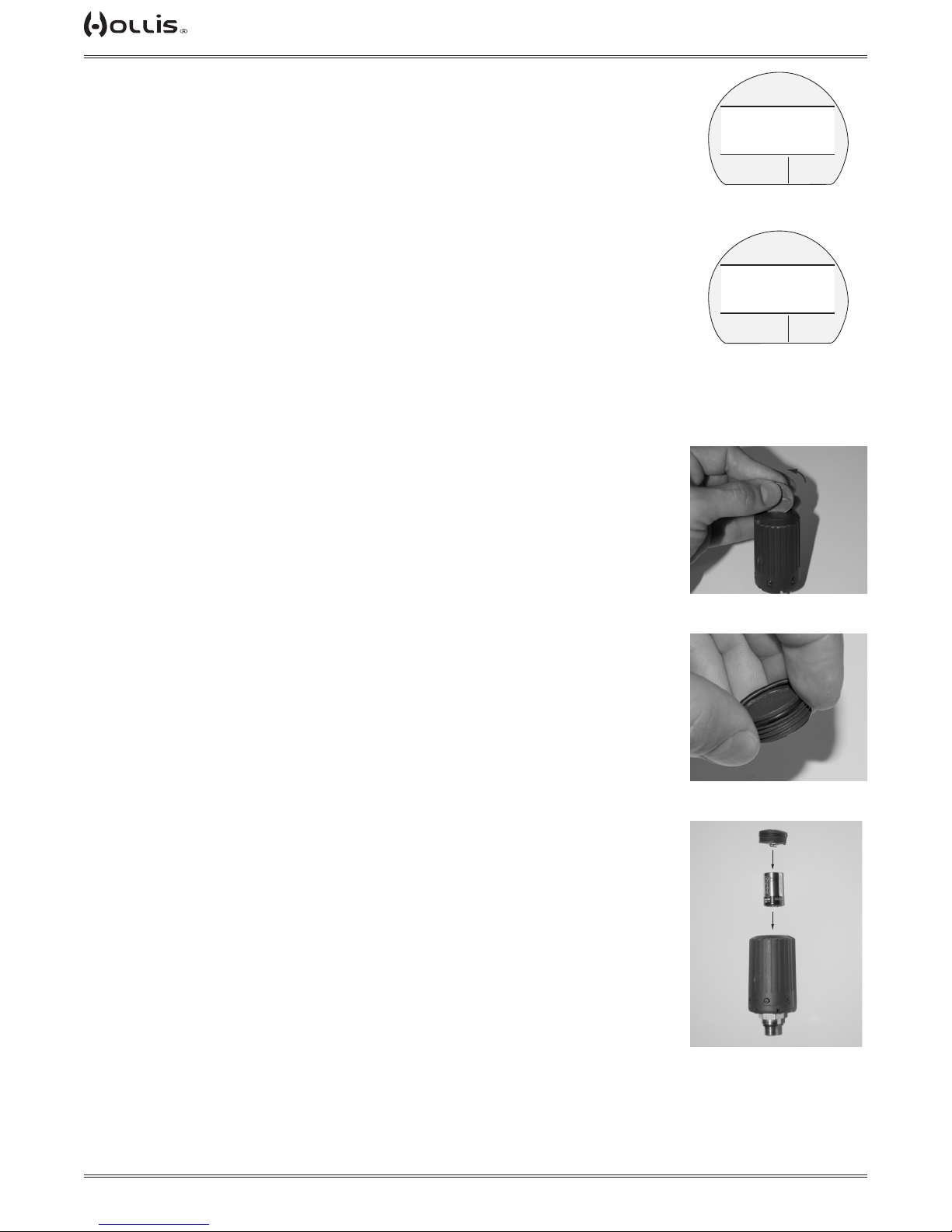
TX1 He OPERATING MANUAL
Testing
> Ensure that the LCD is clear and sharp in contrast. If any portions are missing or
appear dim, or if a Low Battery condition is indicated, return the TX1 He with Transmitter to an Authorized Hollis Dealer for evaluation before use.
> During 24 hours after completion of a dive, the graphic DATA with selections SAVE
and CLEAR will be displayed giving you the option to retain or delete settings and NiO2 calculations for repetitive dives.
• Press the A button to toggle between SAVE and CLEAR.
• Press the S button to save the selection.
DATA
>SAVE?
CLEAR?
SELECT ITEM
> Graphics DATA SAVED (or CLEARED) with CAL COMPASS appear for 3 seconds,
then operation reverts to the
Compass CAL screen.
> Calibrate the Compass. Refer to page 63.
> Verify all Set Points prior to diving.
• Pressurize the Regulator assembly (with Transmitter).
• Verify that the Link icon is displayed.
• Check the TMT Status screens. Refer to page 23.
TRANSMITTER BATTERY REMOVAL
Locate the Battery Cover on the end of the housing:
• Apply a coin to the recessed slot of the Cover and turn it counter clockwise out of
the housing.
• Remove the Battery and discard it according to local regulations governing disposal
of Lithium batteries.
TRANSMITTER BATTERY INSTALLATION
• Lightly lubricate the new Battery Cover O-ring with silicone grease and install it onto
the Battery Cover. DO NOT roll the O-ring over the Threads, instead stretch it slightly
to work it down over the slotted end of the Cover into the groove at the base of the
threads.
• The O-ring must be a genuine Hollis part that can be purchased from an Authorized
Hollis Dealer.
DATA
SAVED
CAL COMPASS
DATA SAVED
OPEN
TMT COVER REMOVAL
Use of any other O-ring will void the warranty.
• Place a new 3 volt CR2 Lithium Battery (Duracell model DL-CR2 or equivalent)
positive (+) side down into the Battery compartment with the negative end facing up/
out.
• Ensure that the Battery is properly oriented and the Cover O-ring is evenly seated
around the Cover.
• Carefully place the Cover (with Spring) into the housing and turn clockwise slowly
by hand to ensure proper threading.
• Apply a coin and tighten until secure. The outer surface of the Battery Cover should
be ush with the outer surface of the housing.
© 2002 DESIGN (2014)
70
INSTALLING COVER O-RING
-
+
BATTERY ORIENTATION
Doc. 12-4101-r06 (1/21/14)
Page 71
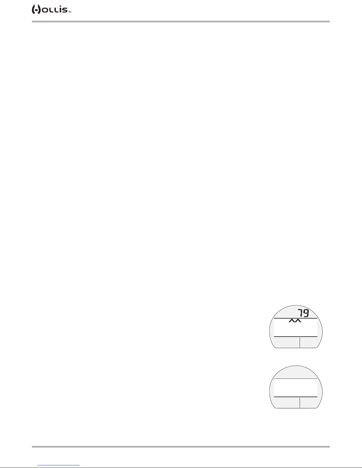
TX1 He OPERATING MANUAL
INSTALLING A TRANSMITTER ON A REGULATOR
• Remove the existing pressure gauge and high pressure hose, or the high pressure
port plug from the port marked HP using the proper size hex key.
• Lightly lubricate the O-ring and threads of the Transmitter tting with a halocarbon
based lubricant such as Tribolube® 71 or Christo-Lube® MCG111.
• Thread the Transmitter clockwise by hand into the regulator's HP port and tighten
until secure with an appropriate sized open end wrench.
• Attach the regulator First Stage to a full scuba tank and pressurize by slowly open-
ing the tank valve, listening for any indication of air leaking around the tting.
• If air leakage is present, DO NOT use, take the complete regulator assembly to an
Authorized Hollis Dealer for inspection and service.
TRANSMITTER COMPATIBILITY WITH NITROX
When packaged and shipped from the factory, Hollis Transmitters are rated for use
with compressed Air, Nitrox, and Trimix breathing gas mixtures containing up to 99%
O2 by volume and with 100% O2.
ALTITUDE SENSING AND ADJUSTMENT
Prior to the rst dive of a series of repetitive dives, Altitude (i.e., ambient pressure) is
measured upon activation then every 15 minutes until a dive is made.
> Measurements are only taken when the unit is dry.
> Two readings are taken, the second reading 5 seconds after the rst. The readings
must be within 1 foot (30 cm) of each other to record that ambient pressure as the
current Altitude.
> No adjustments are made during any time that the Wet Contacts are bridged.
When diving in high altitude waters from 3,001 to 14,000 feet (916 to 4,270 meters),
the TX1 He automatically adjusts to these conditions providing corrected Depth, and
reduced No Deco and O2 Times at intervals of 1,000 feet (305 meters).
At an elevation of 3,001 feet (916 meters), Depth calibration automatically changes
from feet of seawater to feet of fresh water. This is the rst adjustment to the algorithm.
The TX1 He will not function above 14,000 feet (4,270 meters).
RESET DURING A DIVE
The intent of the feature is to assist the diver by providing indication of Depth during
the ascent and encourage return of the affected unit to the factory for evaluation prior
to further use.
If the TX1 He Resets (i.e.; is On, turns Off, then turns On again) for any reason during any dive, inert gas, O2, and GTR calculations are terminated (upon turning Off).
Upon turning On, the graphic ERROR and the UP Arrow icons appear solid, and
Current
Depth is displayed. No other information is displayed. The Backlight remains operational.
Upon surfacing, the graphic ERROR is displayed solid for 5 seconds, then the unit
will shut off with operation blocked permanently, even if the battery is replaced and
attempts are made to reactivate the unit.
! WARNING: In the unlikely event that this should ever happen, DO NOT
continue diving with the unit, return it to the factory as soon as possible.
>
>
ERROR
PO2
BAR
ERROR
(during dive)
ERROR
PO2
BAR
ERROR
(after surfacing)
FTM
© 2002 DESIGN (2014)
71
Doc. 12-4101-r06 (1/21/14)
Page 72
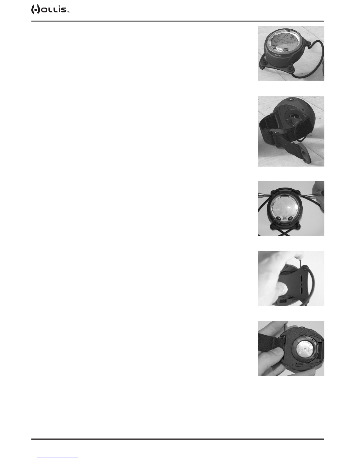
TX1 He OPERATING MANUAL
WRIST STRAP
The TX1 He allows for two different style wrist straps the optional shock cord version (P/N 204.2365) and the standard elastic band version. The shock cord version
is excellent if you will routinely mount the TX1 He in the same position and use the
same thermal protection. In this scenario the shock cord version will only need to be
adjusted once. If you nd that you are changing congurations, environments, and
switching from drysuits to wetsuits routinely, you may nd the elastic band version
more convenient.
Strap Removal
There are two retaining screws holding the wrist strap to the TX1 He.
• Using two small blade style screwdrivers, turn the opposing screw heads counter
clockwise to remove. It may be necessary to use a ne needle or pick to pull the
screws from the TX1 module boot if they do not drop out. Be careful to not scratch or
damage any parts in doing so.
• Repeat the above step for the other retaining screw.
• With the retaining screws removed, the strap should lift away from the computer
body.
Strap Replacement
Installing the shock cord or elastic band versions is essentially the same.
• Align and hold the strap end or plastic base in place on the computer body as
shown.
• While holding the strap end or plastic base in place, slide the long screw post
through the body and strap end or plastic base.
• On the opposing side thread and tighten the retaining screw clockwise into the
screw post with a small at blade screwdriver*. DO NOT overtighten. It will be neces-
sary to hold one end stationary with a small at blade screwdriver when doing this.
*The threads of the screws must be clean, and a drop of medium strength liquid
thread lock should be applied to the retaining screw before installation.
• Repeat the above steps for the other strap end and retaining screw.
SHOCK CORD
WRIST STRAP
ELASTIC BAND
WRIST STRAP
REMOVING RETAINING
SCREW
© 2002 DESIGN (2014)
72
REPLACING SCREW
(shock cord version)
REPLACING SCREW
(elastic band version)
Doc. 12-4101-r06 (1/21/14)
Page 73

TX1 He OPERATING MANUAL
Adjusting the Shock Cord Version (P/N 204.2365)
The shock cord should be tted in position over any gloves, wetsuit, or drysuit. Keep
in mind neoprene compresses with depth, and compensate the tension accordingly.
• Knot one end of the shock cord.
• Thread the other end of the shock cord through the eyelets, as shown in sequence
(arrow 1 - 4).
• Pull the loose end until the proper tension is reached.
• Then tie a new knot to hold the tension.
• Cut the excess shock cord*. Then burn the freshly cut end of the shock cord with a
match or lighter to avoid future fraying.
*You may want to try the new shock cord length on an actual dive before cutting
the shock cord. Once the shock cord is cut too short, it will need to be replaced to
lengthen once again.
3
2
1
4
ADJUSTING THE
SHOCK CORD
© 2002 DESIGN (2014)
73
Doc. 12-4101-r06 (1/21/14)
Page 74

TX1 He OPERATING MANUAL
TECHNICAL DATA
© 2002 DESIGN (2014)
74
Doc. 12-4101-r06 (1/21/14)
Page 75

TX1 He OPERATING MANUAL
SPECIFICATIONS
CAN BE USED AS
• Dive Computer (Air, Nitrox, or Trimix) with up to 6 Gases, 6 Transmitters, and gas mixes containing up to 100% O2.
• Digital Depth Gauge/Timer with up to 6 Transmitters.
• Compass.
DIVE COMPUTER PERFORMANCE
• Bühlmann ZHL-16c w/Gradient Factors, algorithm.
• Decompression in agreement with Bühlmann ZHL-16c.
• No Deco Deep Stops >> Morroni, Bennett.
• Deco Deep Stops >> Blatteau, Gerth, Gutvik.
• Altitude >> Bühlmann, IANTD, RDP (Cross).
• Altitude corrections and O2 limits based on NOAA tables.
TRANSMITTERS (TMTs)
• Battery and Pressure check
> every 2 seconds when awake
• Startup
> Pressure ≥ 120 PSI (8 BAR)
> Battery ≥ 2.75 volts
• Shutdown
> Pressure < 50 PSI (3.5 BAR)
TMT Compatibility with Nitrox
• When packaged and shipped from the factory, Hollis Transmitters are rated for use with compressed Air and Nitrox mixtures containing up to 99% O2
by volume and with 100% O2.
OPERATIONAL PERFORMANCE
Function: Accuracy:
• Depth ±1% of full scale
• Timers 1 second per day
Dive Mode Activation:
• Must rst be activated by button press, if Wet Activation is set OFF.
• Automatic by immersion in water, if Wet Activation is set ON.
• Cannot be manually activated deeper than 4 FT (1.2 M), if Wet Activation is set OFF.
• Cannot operate as a DC at elevations higher than 14,000 feet (4,270 meters).
Unit Shutoff:
• 2 hours after activation, if no dive conducted.
• 24 hours after conducting a dive, if no further dives conducted.
Dive Counter:
• NORM/GAUGE displays Dives #1 to 24 (0 if no dive made yet).
• Resets to Dive #1, upon diving (after 24 hours with no dives).
Dive Log Mode:
• Stores 24 most recent NORM/GAUGE dives in memory for viewing.
• After 24 dives, adds 25th dive in memory and deletes the older dive.
Altitude:
• Operational from sea level to 14,000 feet (4,270 meters) elevation.
• Measures ambient pressure upon activation and every 15 minutes while in Surface modes.
• Does not measure ambient pressure when Wet.
• Compensates for Altitudes above sea level beginning at 3,001 feet (916 meters) elevation and every 1,000 feet (305 meters) higher.
Power:
• Battery (1) 3 vdc, CR2450, Lithium battery (Panasonic or equivalent)
• Transmitter Battery (1) 3 vdc, CR2, .75 Ahr, Lithium battery (Duracell model DL-CR2 or equivalent)
• Shelf life Up to 5 years
• Replacement User replaceable (annual recommended)
• Use Life 1 year or 300 dive hours if (2) 1 hour dives per dive day
• Use Life (Transmitter) 300 dive hours if (2) 1 hour dives per dive day
Battery Indicator:
• Warning >> icon on solid when ≤ 2.75 volts, Battery change recommended.
• Alarm >> icon on ashing when ≤ 2.50 volts, change the Battery, will not function.
Operating Temperature:
• Out of the water >> between 20 °F and 140 °F (-6 and 60 °C).
• In the water >> between 28 °F and 95 °F (-2 and 35 °C).
© 2002 DESIGN (2014)
SPECIFICATIONS (CONTINUED)
75
Doc. 12-4101-r06 (1/21/14)
Page 76

TX1 He OPERATING MANUAL
BAR GRAPHS:
TLBG segments
• No Deco Normal zone 1 to 3
• No Deco Caution zone 4
• Decompression zone 5 (all)
VARI 60 FT (18 M) & Shallower Deeper than 60 FT (18 M)
segments FPM MPM segments FPM MPM
0 0 - 10 0 - 3 0 0 - 20 0 - 6
• Normal zone 1 11 - 15 3.5 - 4.5 1 21 - 30 6.5 - 9
Normal zone 2 16 - 20 5 - 6 2 31 - 40 9.5 - 12
Normal zone 3 21 - 25 6.5 - 7.5 3 41 - 50 12.5 - 15
• Caution zone 4 26 - 30 8 - 9 4 51 - 60 15.5 - 18
• Too Fast zone (ashing) 5 (all) > 30 > 9 5 (all) > 60 > 18
NUMERIC DISPLAYS: Range: Resolution:
• Time of Day 0:00 to 23:59 hr:min 1 minute
• PCI Countdown Timer 1:59 to 0:00 min:sec 1 second
• Altitude Level Sea, EL-2 to EL-7 1 (level)
• Time to Fly 23:50 to 0:00 hr:min 1 minute
• Time to Desaturate 23:50 to 0:00 hr:min 1 minute
• Temperature 0 to 99°F (-18 to 60°C) 1°F (C)
• Depth (display) 0 to 400 FT (120 M) 1 FT (0.1/1 M )
• Max Op Depth (NORM) 400 FT (120 M)
• Max Op Depth (GAUGE) 400 FT (120 M)
• Tank Pressure 0 to 5000 PSI (345 BAR) 5 PSI (1 BAR)
• NORM/GAUG SI Time 0:00 to 23:59 hr:min 1 minute
• NORM/GAUG Dive Number 0 to 24 1 (dive)
• NORM/GAUG EDT 0 to 999 min 1 minute
• NORM DTR 0 to 999 min 1 minute
• NORM/GAUG GTR 0 to 199 min 1 minute
• FO2 (1, 2, 3, 4, 5, 6) Set Points Air, 21 to 100 % 1 %
• FHe (1, 2, 3, 4, 5, 6) Set Points 0 to 93% 1 %
• PO2 Value 0.00 to 5.00 ATA 0.01 ATA
• O2 Saturation 0 to 100 % 1 %
• GF High 10 to 90 1
• GF Low 10 to 90 1
• No Deco Deep Stop Time 2:00 to 0:00 min:sec 1 second
• No Deco Safety Stop Time 5:00 to 0:00 min:sec 1 second
• Safety Stop Timer 0:00 to 9:59 min:sec 1 second
• GAUGE Dive Run Timer 0 to 999 min 1 minute
• Deco Stop Time 1 to 99 min 1 minute
• Total Ascent Time 1 to 199 min 1 minute
• Violation Countdown Timer 23:50 to 0:00 hr:min 1 minute
• Compass Heading 001 to 360° 001°
• Compass Op Time Remaining 15 to 1 sec 1 sec
© 2002 DESIGN (2014)
76
Doc. 12-4101-r06 (1/21/14)
Page 77

TX1 He OPERATING MANUAL
! WARNING: If your TX1 He stops working for any reason while operating, it is important that you
have anticipated this possibility and are prepared for it. This is an important reason for not pushing the tables, oxygen exposure limits, and a critical reason to avoid entering decompression,
without proper training. If you dive in situations where your trip would be ruined or your safety
would be jeopardized by losing the use of your TX1 He, a backup instrument system is highly
recommended.
FCC COMPLIANCE:
This equipment complies with Part 15 of the FCC Rules. Operation is subject to the following two conditions: 1.) this equipment may not cause harmful interference, and 2.) this equipment must accept any
interference received, including interference that may cause undesired operation.
FCC INTERFERENCE STATEMENT:
This equipment has been tested and found to comply with the limits for an Intentional Radiator, a Class
B Digital Device, pursuant to Part 15 of FCC Rules, Title 47 of the Code of Federal Regulations. These
rules are designed to provide reasonable protection against harmful interference in a commercial or residential installation. This equip-ment generates, uses and can radiate radio frequency energy and, if not
installed and used in accordance with the instructions, may cause harmful interference to radio communications.
There is no guarantee that interference will not occur in a particular installation. If this equipment does
cause interference to radio or television reception, which can be deter-mined by turning the equipment off
and on, the user is encouraged to try to correct the interference by one or more of the following measures:
• Reorient or relocate the receiving antenna.
• Increase the separation between the equipment and receiver.
• Connect the equipment to an outlet on a circuit different from that to which the receiver is connected.
• Consult the dealer or an experienced radio/TV technician.
! WARNING: Changes or modication to this unit not expressly approved by HOLLIS/2002 Design
could void the user's authority to operate the equipment.
© 2002 DESIGN (2014)
77
Doc. 12-4101-r06 (1/21/14)
Page 78
TX1 He OPERATING MANUAL
INSPECTION / SERVICE RECORD
TX1 HE SERIAL NUMBER:
TX1 HE FIRMWARE REV:
TRANSMITTER 1 SERIAL NUMBER:
TRANSMITTER 2 SERIAL NUMBER:
TRANSMITTER 3 SERIAL NUMBER:
TRANSMITTER 4 SERIAL NUMBER:
TRANSMITTER 5 SERIAL NUMBER:
TRANSMITTER 6 SERIAL NUMBER:
DATE OF PURCHASE:
PURCHASED FROM:
Below to be lled in by an Authorized Hollis Dealer:
Date Service Performed Dealer / Technician
HOLLIS USA
2002 Davis Street
San Leandro, CA 94577
Tel: (510) 729-5110
Fax: (510) 729-5115
Web: www.HollisGear.com
E-mail: [email protected]
International Ofces
See (http://hollisgear.com/international.asp) for current contact info.
© 2002 DESIGN (2014)
78
Doc. 12-4101-r06 (1/21/14)
 Loading...