

Page 1
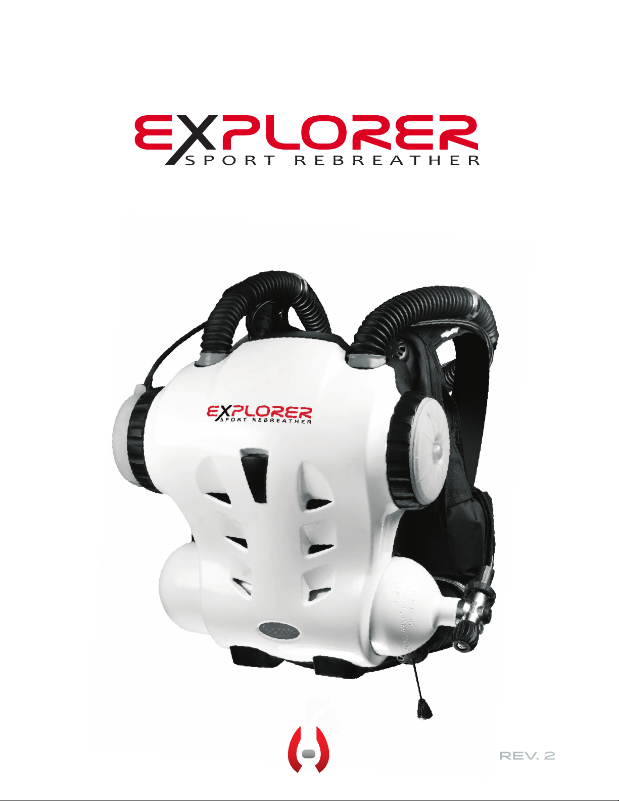
user Manual
REV. 2
Page 2
This is the operations manual for the
HOLLIS EXPLORER
This manual, specifications and features of the Explorer are proprietary and
copyright Hollis Inc., 2012.
This document cannot be copied or distributed without the prior agreement and
authorization from Hollis Inc.
All information contained is subject to change. Contact the manufacturer for the
latest information. www.hollisgear.com
The EXPLORER is manufactured in the USA by Hollis Inc.,
2002 Davis Street, San Leandro, CA 94577. USA
Ph (510) 729-5100
EC Type approved by SGS UK Ltd. Weston-super-Mare. BS22 6WA. Notified
Body No. 0120.
Testing conducted by ANSTI Test Systems. Hants.
To ensure your user information is up to date. Please check
www.hollisgear.com/support.asp for updates to this manual.
For warranty information see www.hollisgear.com/support_warranty.asp
DANGERS, WARNINGS, CAUTIONS, AND NOTES
Pay attention to the following symbols when they appear throughout this document. They denote important information and tips.
!
DANGERS: are indicators of important information that if ignored would lead
to severe injury or death.
WARNINGS: are indicators of important information that if ignored could lead
!
to severe injury or death.
CAUTION
CAUTIONS: are indicators of information that if ignored may lead to minor to
moderate injury.
NOTES: indicate tips and advice that can inform of features, aid assembly, or
prevent damage to the product.
Page 3

EXPLORER DESIGN TEAM
Bob Hollis
Kevin Gurr
HollisExplorer
User Manual
Document Control Number: 12-4102
Rev. 2
Publish Date: 7/26/2013
WARNING:
!
USE OF THE EXPLORER MANUAL
This user manual does not, nor is it intended to
contain any information needed to safely dive with
any type of SCUBA apparatus. It is designed as a
guide for the proper setup, operation, maintenance,
and field service of the Hollis Explorer only. It does
NOT take the place of a recognized training agency
instructor-led diver-training course or its associated
training manual(s) and materials. This user manual
is intended to be used only as a type specific addition to such training and materials, and as a user
reference. This manual cannot be used as a substitute guide for any other type of Self Contained
Underwater Breathing Apparatus (SCUBA).
Photo by:
www.HINDL.com
Page 4

GENERAL SAFETY
STATEMENTS + WARNINGS
WARNING:
!
GENERAL SAFETY
No person should breathe from, or attempt to operate in any way, a Hollis Explorer rebreather, or any
component part thereof, without first completing an appropriate Hollis Certified user-training course.
Further, no Explorer diver should use a Hollis Explorer without direct Hollis instructor supervision until
they have mastered the proper set-up and operation of the Hollis Explorer rebreather. This includes
new Explorer divers as well as Explorer certified divers who have been away from diving for an extended period of time and would benefit from an instructor-led refresher course to regain skills and mastery
of the Hollis Explorer. Failure to do so can lead to serious injury or death.
WARNING:
!
NITROX STATEMENT
The EXPLORER equipment is classified as being suitable for use with nitrogen-oxygen (Nitrox) breathing gas mixtures containing up to 40% oxygen by volume without the need for special preparation,
cleaning , or component parts.
If Explorer equipment is subsequently used with equipment, or connected to an air supply system, that
is not rated for Oxygen Service, it can subsequently be used with Nitrox (up to 40% O2) as long as the
equipment is maintained in accordance with the procedures and parts specified in the Hollis EXPLORER Product Service Guide.
The EXPLORER was designed for use with Nitrox (up to 40% O2). DO NOT use gas mixtures with a
higher fraction of oxygen greater than 40% with your EXPLORER.
WARNING:
CAUSTIC MATERIAL
The CO2 absorbent used in the scrubber is caustic alkaline material. Take steps to protect yourself from
direct lung and skin contact. Furthermore, poor management of the breathing loop could lead to water
contact with the CO2 absorbent, causing a “caustic cocktail” (very caustic liquid). This could lead to se-
vere chemical burns and if inhaled - possible drowning. Proper handling procedures, pre-dive checks,
dive techniques, and maintenance mitigates this risk.
iv |
Page 5

WARNING:
!
DESIGN AND TESTING
The Hollis Explorer has been designed and tested, both in materials and function to operate safely
and consistently under a wide range of diving environments. You must not alter, add, remove, or reshape any functional item of the Hollis Explorer. Additionally, NEVER substitute any part of the Hollis
Explorer with third-party items which have not been tested and approved by Hollis for use with the
Explorer.
This includes, but is not limited to, hoses, breathing assemblies, electronics, breathing gas delivery
assemblies and their constituent parts, sealing rings, valves and their constituent parts and sealing
surfaces, latches, buoyancy devices, inflation and deflation mechanisms and on-board alternate
breathing devices.
Altering, adding, removing, re-shaping or substituting any part of the Hollis Explorer with non-approved parts can adversely alter the breathing, gas delivery or CO2 absorption characteristics of the
Hollis Explorer and may create a very unpredictable and dangerous breathing device, possibly leading to serious injury or death.
Non-approved alterations to functional parts of the Explorer will automatically void all factory warranties, and no repairs or service work will be performed by any Hollis service professional until the
altered Explorer unit is brought back into factory specifications by a Hollis service professional at the
owner’s expense.
WARNING:
!
COMPUTER / CONTROLLER-SPECIFIC WARNINGS
This computer is capable of calculating deco stop requirements. These calculations are predictions of
physiological decompression requirements. Calculations are for contingency use only. The Explorer
in this “sport” configuration is not intended for decompression use.
| v
Page 6

TABLE OF CONTENTS
General Safety Statements & Warnings
PART 1
YOUR NEW EXPLORER
SECTION 1
REBREATHER LIFE SUPPORT SYSTEM
RULES
SECTION 2
BATTERIES
SECTION 3
UNIT LAYOUT
SECTION 4
COVER REMOVED
SECTION 5
GAS FLOW
SECTION 6
MECHANICAL FEATURES
PART 2
OUT OF THE BOX
SECTION 1
INITIAL ASSEMBLY
PART 3
LIFE SUPPORT SYSTEM
(COMPUTER)
SECTION 1
GENERAL OPS
SECTION 2
AUTOMATIC TURN ON
SECTION 3
DISPLAY SYMBOLS
SECTION 4
SCREEN ICONS
SECTION 5
DIVE SCREENS
SECTION 6
STATUS SCREENS
SECTION 7
MAIN MENU
SECTION 8
SETUP MENU
iii-v
SECTION 9
BAILOUT & GAS CONFIGURATION
SECTION 10
DCP (DIVE CONTROL PARAMETER)
SECTION 11
RMS(RESOURCES MANAGEMENT SYSTEM)
SECTION 12
O2 SENSOR CALIBRATION
SECTION 13
O2 SENSOR VOTING
SECTION 14
CDM (CANISTER DURATION METER)
SECTION 15
DISPLAY & ALARM SYSTEMS
SECTION 16
ALARM FLOW DIAGRAMS
SECTION 17
GAS RESERVES
SECTION 18
MOD (MAXIMUM OPERATING DEPTH)
SECTION 19
DECO CONTINGENCY
SECTION 20
INTERNET REPROGRAMMING
PART 4
GETTING READY TO DIVE
SECTION 1
GEAR PREP
SECTION 2
PRE-DIVE SETUP
SECTION 3
COMPLETING PRE-DIVE CHECKS
SECTION 4
USER FAULT FINDING & TESTING
PART 5
MANDATORY DIVING SKILLS
SECTION 1
EXPLORER BASICS
SECTION 2
IN-WATER SKILLS CHART
vi |
Page 7

SECTION 3
EXPLORER SKILLS COMPLETED
PART 6
COMPLETE DISASSEMBLY &
REASSEMBLY
SECTION 1
THE FULL DEAL
PART 7
USER MAINTENANCE & ABSORBENT STORAGE
SECTION 1
O2 SENSORS
SECTION 2
SANITIZING
SECTION 3
CO2 ABSORBENT
SECTION 4
SERVICE
SECTION 5
MAINTENANCE SCHEDULE
PART 8
APPROVED PRODUCTS &
GLOSSARY
SECTION 1
APPROVED PRODUCTS
SECTION 2
GLOSSARY
| vii
Page 8
1.1
Your New Explorer
Rebreather LifE Support
System Rules
!
DANGER: Read and understand this list prior to using this unit.
Rules for EXPLORER Diving
1. Always complete all pre-dive checks. Pay special attention to BOV
mushroom valve tests.
2. Always pre-breathe the Explorer Sport Rebreather until the system
passes its’ tests.
3. Do not modify the EXPLORER without the manufacturer’s written consent.
4. Do not use a full-face mask, Unless approved by Hollis for use with the
EXPLORER
5. Always analyse your gas.
6. Never dive a unit you suspect is leaking and has not passed all the predive tests.
7. Never leave your BOV open on the surface
8. Ensure your BC is inflated at the surface.
9. Take time to adjust your weight correctly, do not dive over-weighted.
10. Always dive with buoyancy control and buoyancy inflation.
11. Practice a skill on every dive.
12. Avoid unnecessary mask clearing.
13. Regularly sanatize the unit.
14. Never exceed the CO2 alarms.
15. Never hold your breath
16. Never start a dive with a low battery alarm.
17. Always carry bailout gases of sufficient volume for the planned dive as
per your training agency recommendations.
If you do not understand any or all of this section please contact your training agency or Hollis.
2 |
IF IN DOUBT BAIL OUT!
Page 9
BATTERIES
The EXPLORER uses Lithium Polymer batteries. These rechargeable batteries are very efficient and provide many years of reliable operation.
Rechargeable Lithium batteries can be recharged at any time and do not
have a significant memory affect, which would otherwise cause unreliable
battery operation. The batteries are UL listed (flight safe) and are double
sealed to reduce the chance of leakage to a minimum.
As extra confidence, the LSS Module battery pack includes 3 separate
batteries to ensure operation even under multiple battery failure scenarios.
During diving the battery reserve alarm will indicate when there is still sufficient battery to allow a return to the surface with a small reserve. The unit
MUST then be charged prior to diving again.
1.2
The handset has its own battery that is charged from the EXPLORER Module automatically.
The user should keep the batteries recharged and topped up to ensure
there is always maximum capacity for any dive.
A fully charged battery pack will display 1000 minutes of battery life.
!
DANGER: The battery estimate is based on current temperature, light usage on the handset, DCP setting and other variables. Changes in conditions (i.e. cold water) may shorten burn
times. Plan dives accordingly, and always monitor the HUD and
Wrist Displays for system operation status.
NOTE: The EXPLORER must be fully charged before its rst
use. Always dry the Optocon charge connector before attaching the charging connector. Damage may result if this is not
done.
Check that all parts of the charger are kept dry and only used indoors.
Battery level alarms will activate when the batteries get low. When Battery
level alarms will activate when the batteries get low. When a battery low
alarm is activated this will be displayed on the Status screen.
WARNING: DO NOT dive a battery level, which is less than
!
twice your expected dive time for the next dive.
| 3
Page 10
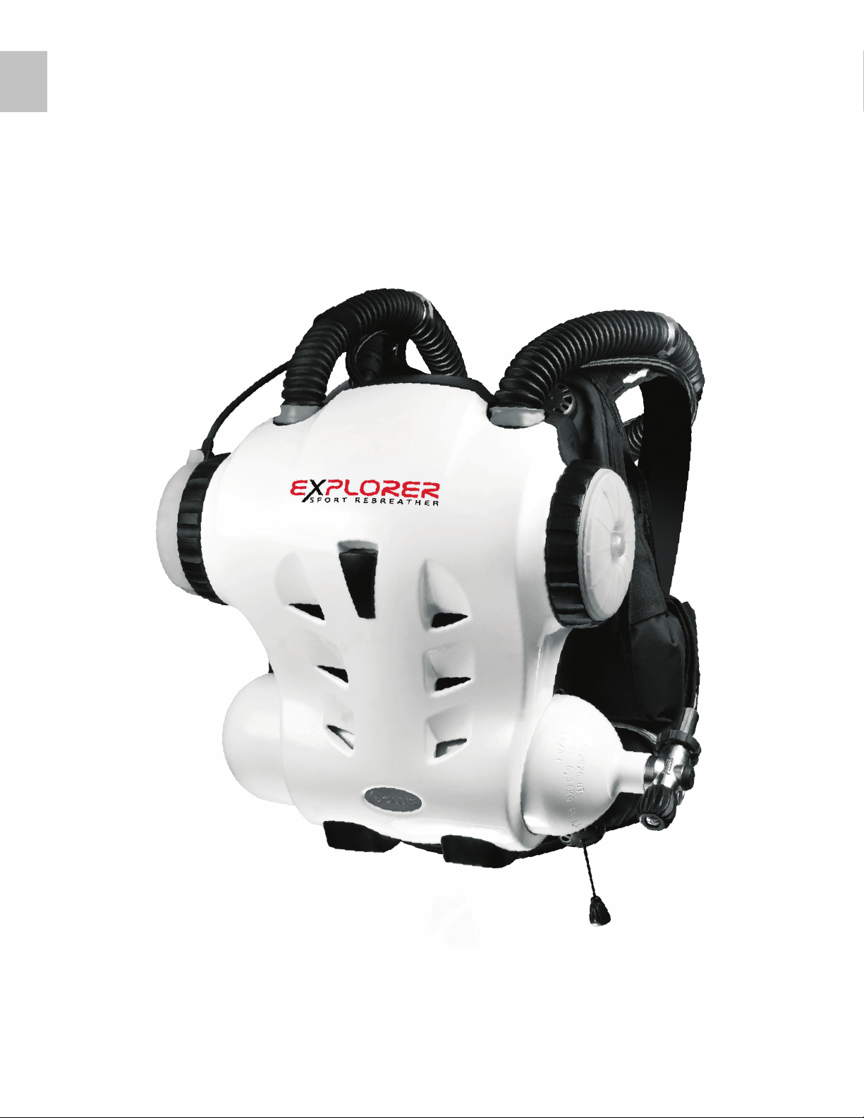
1.3
ASSEMBLED UNIT
4 |
Page 11
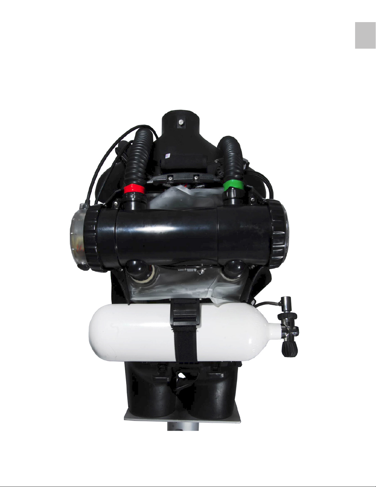
Cover Removed
1.4
| 5
Page 12
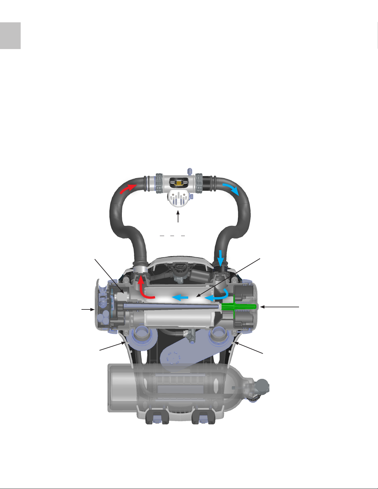
1.5
GAS FLOW
As the diver exhales gas flows through the hose (blue arrow) and over the
right shoulder. It then enters the absorbent filter and flows across the Oxygen and CO2 sensors in the Sensor Module and through the inhale hose
(red arrow) and back to the mouthpiece.
Gas also naturally flows in and out of the exhale and inhale counterlungs.
Electronics
Inhale
Counterlung
O2 & CO
Sensors
BOV
(Bailout Valve)
2
Absorbent
Filter
Filter
“In - Out”
Indicator
Exhale
Counterlung
6 |
Page 13
Mechanical Features
The EXPLORER is an electro-mechanical rebreather. Over time certain software and hardware optional extras and/or software upgrades will become
available. Please check www.HollisGear.com for details.
HARNESS/BCD
EXPLORER uses a custom bolt fitting, backplate, Solo webbing harness,
and Hollis C45LX Wing. There is an optional EXPLORER BCD available.
COUNTERLUNG
The EXPLORER comes complete with dual back-mounted counterlungs
(BCL). These are attached to the canister by a screw threaded O-ring
fitting.
1.6
CYLINDER
EXPLORER uses a 5L/40cuft cylinder with an inline valve. Dives over 18
m/60 ft requires that an additional bailout cylinder of a minimum capacity
of 3 L/20 cuft be used in conjunction with the 5L/40 cu ft cylinder.
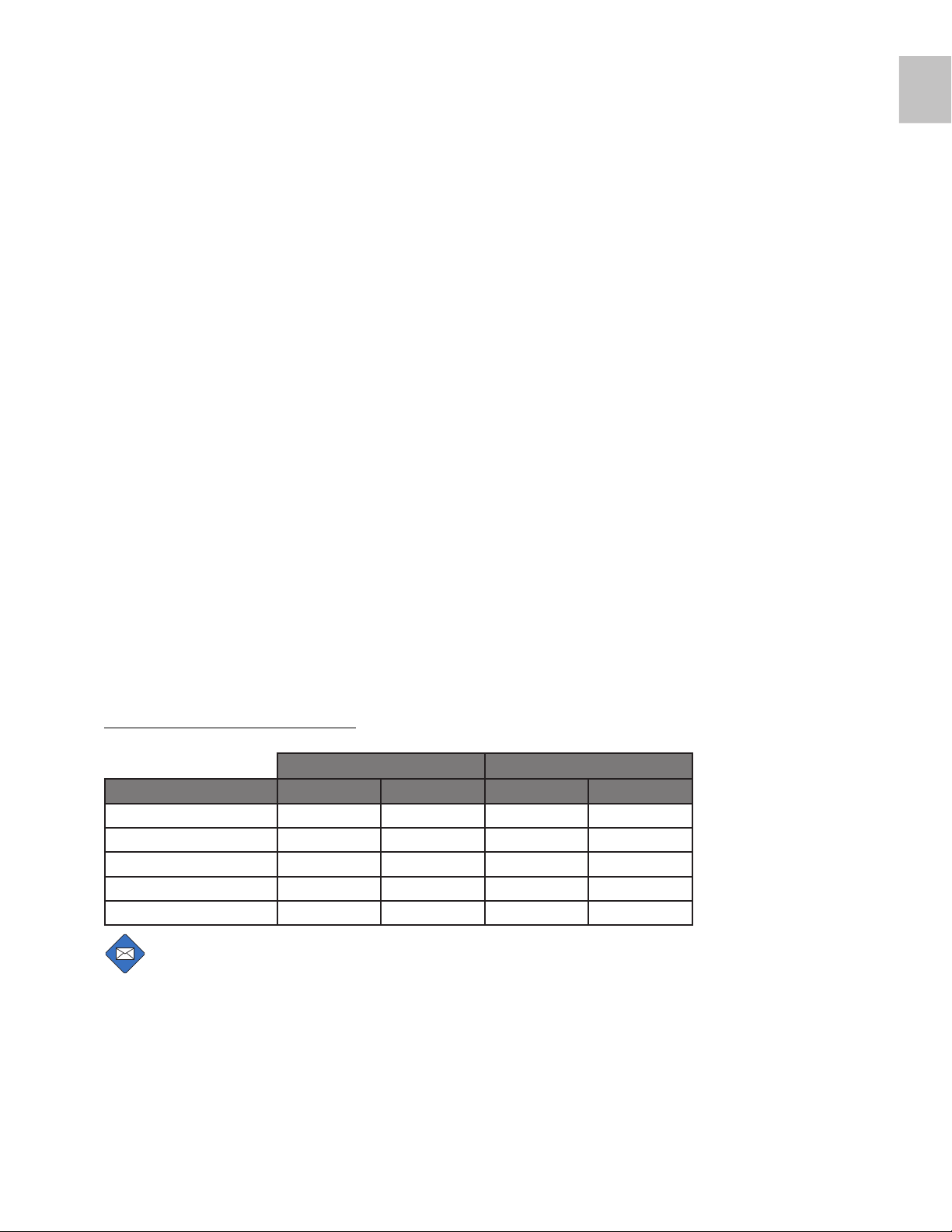
USA Only Cylinder Options Chart
Capacity Working pressure
Manufacturer WC (L) WC (CU/FT) BAR PSI
Beever (Eurocylinders) 5 41 232 3410
Luxfer (US) 4.9 40 204 3000
Catalina 4.3 35.26 204 3000
Faber 5 41 232 3410
Faber 6 49 232 3410
NOTE: The Explorer can accomadate a maximum 5.5 in/14 cm
diameter tank.
| 7
Page 14
CC
OC
EU Only Cylinder Chart
Capacity Working pressure
Manufacturer WC (L) WC (CU/FT) BAR PSI
Faber 5 41 232 3410
Beever (Eurocylinders) 5 41 232 3410
OUTER CASE
The outer case is made from high impact plastic.
OVER-PRESSURE VALVES
EXPLORER uses a combined water release and balanced Loop Control
Valve (LCV). The balanced valve ensures that, the underwater release
pressure is near-constant in any orientation. When the unit vents it also
removes any water from the exhale counterlung. This is best conducted in
a heads up position.
In addition there is a master (high flow) over pressure release valve that is
set to 40mb to help control ascents.
BOV (BAILOUT VALVE)
EXPLORER comes with a BOV. The BOV attaches to the on-board nitrox
circuit. The BOV is designed as the primary bail out (providing a sufficient/
planned volume is carried).
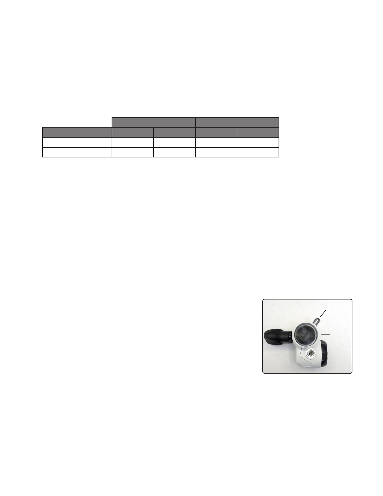
The BOV has two modes (Fig. 1.1):
• OC (Open Circuit Position)
• CC (Closed Circuit Position)
When the mouthpiece is open, the BOV is in the closed circuit position and
when the mouthpiece is closed it is open circuit position.
INTELLIGENT HUD (HEADS UP DISPLAY) & BUD (BUDDY UNIVERSAL
DISPLAY)
The Intelligent HUD (Heads Up Display) is attached to the BOV in the divers line of sight. There is also a BUD (Buddy Universal Display) display in
Fig. 1.1
8 |
Page 15

the EXPLORER Module for Dive Buddy/Instructor use.
These displays give full alarm status at all times using a visual and a tactile
alarm system.
SENSORS
The EXPLORER uses 3 oxygen sensors and one gaseous CO2 sensor. It
also uses a wireless HP sensor.
All sensors are automatically calibrated by the electronic control system.
1.6
| 9
Page 16
out of the box
initial assembly
The parts to assemble your EXPLORER include:
1. The Front Case
2. The Back Case
3. The Canister (pre-assembled in the Case Front)
4. The Sensor Module (Pre-assembled into the Canister)
5. The Life Support System (LSS) Module (Pre-assembled into the Canis
ter) secured in the system case
6. The Right Hand End Cap (Pre-assembled into the Canister)
7. The Regulator First Stage (Pre-assembled in the Case Front)
8. The Buoyancy Control Device (BCD)
9. The 5L/40cuft SCUBA cylinder and valve
10. Two Breathing Hoses
11. The combined Dive-Surface Valve (DSV) and Bail-out Valve (BOV)
12. The Absorbent Filter (pre-assembled into the Canister – User Pack
version only)
13. One Exhale counterlung
14. One Inhale counterlung
15. One Loop Control Valve (LCV) counterlung port/tube
16. Three Oxygen Sensors
17. One CO2 Sensor - Optional
18. One power charger
ASSEMBLY
Step 1.
Remove all parts from the split top box.
Step 2.
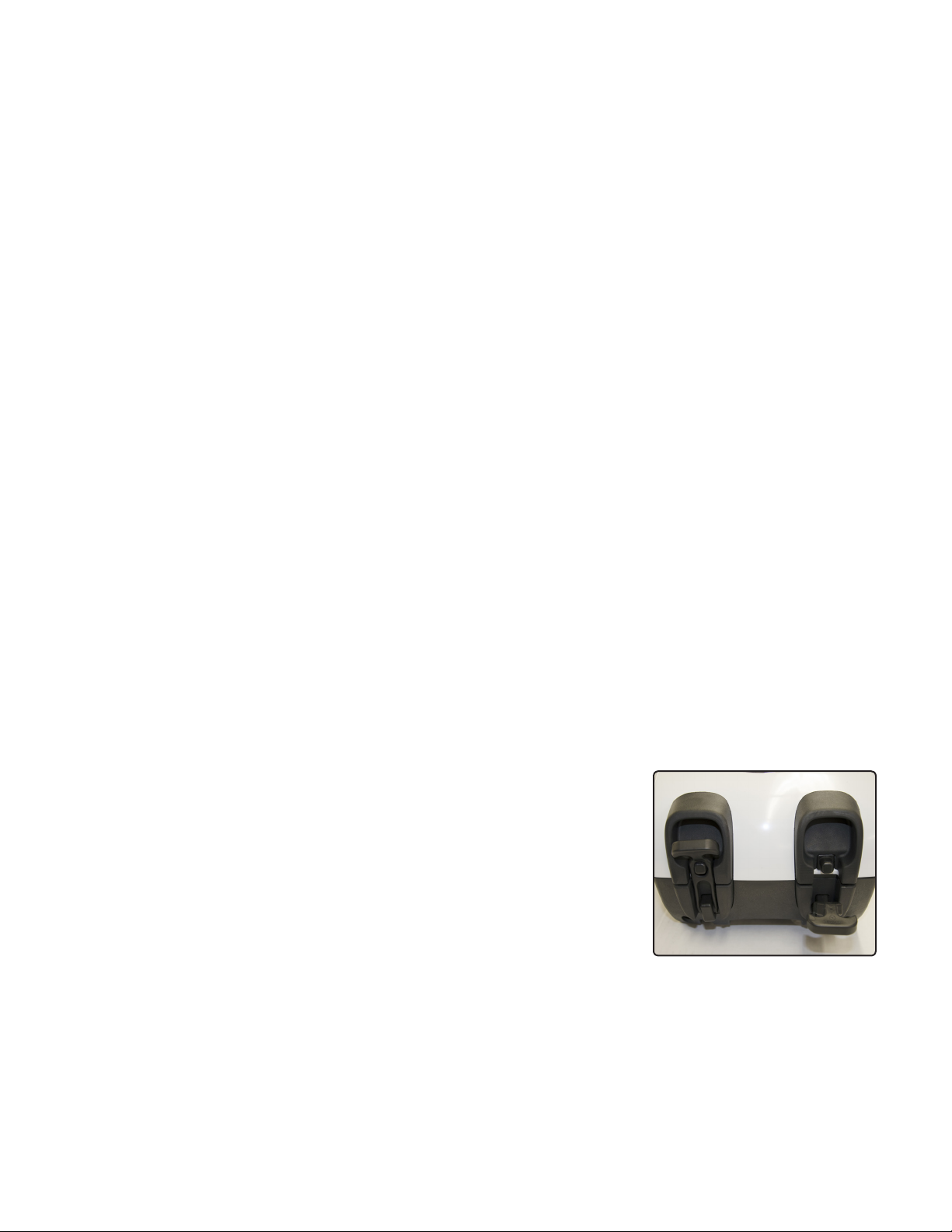
Undo the rubber latches at the base of the Case Front/Back assembly and
lift up the Case Back until the hinge at the top is free (Fig. 2.1). Place to
one side.
Fig. 2.1
10 |
Page 17
Step 3.
Open the box with the Oxygen and CO2 sensors in it. Remove the sensors
from the box and open up the airtight bags.
DANGER: All sensors must be allowed to sit in an AIR atmo-
!
sphere for at least twelve hours prior to use in the EXPLORER.
The Sensors can be immediately assembled into the Sensor
Module but this module should not be fully installed for at least
12 hours after unsealing the sensors packages.
WARNING: After an initial calibration and dive the sensors
!
should be calibrated again after 24 hours.
Step 4.
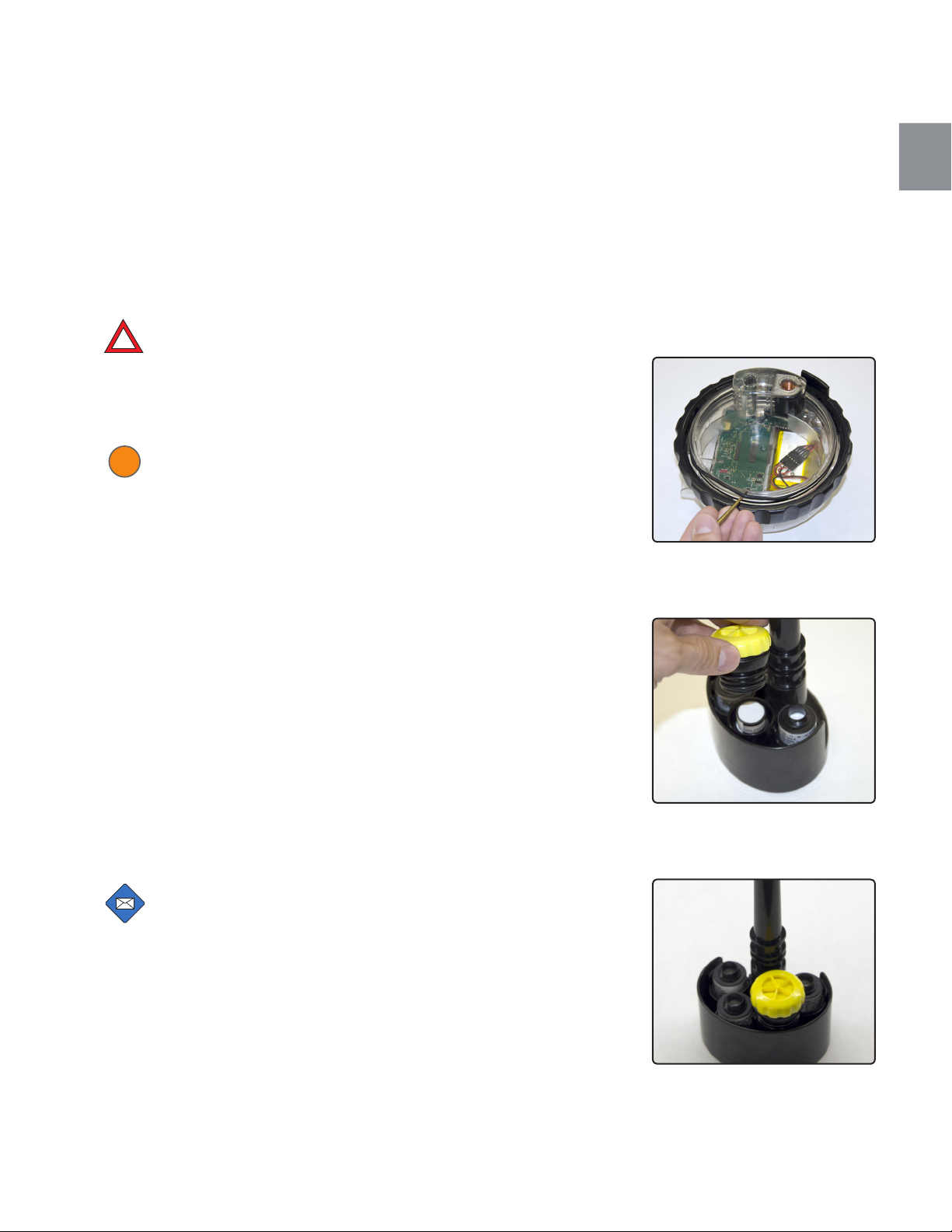
Remove the LSS Module by turning the lock ring ½ turn counterclockwise.
Note the orientation in the Canister.
2.1
Fig. 2.2
Visually* inspect the large sealing O-rings for damage (Fig. 2.2).
Pull the Sensor Module out from the Canister.
Remove the yellow and black CO2 sensor filter cap as shown below (Fig.
2.3). This is a simple O-ring push fit and is retained in place once the Sen-
sor Module is assembled into the Canister, as are all the oxygen sensors.
Push the three oxygen sensors and one CO2 sensor onto their respective
connection points as shown in the picture below.
NOTE: Ensure the oxygen sensors are installed with the white
membrane facing up, as shown.
Inspect the the yellow membrane in the CO2 sensor cap to ensure it's flat in
the holder. Then replace the Sensor Module, and refit the cap (Fig. 2.4).
Fig. 2.3
* The O-ring pick is used in the photo for illustration purposes. It is not
necessary to remove the O-ring before every dive.
Fig. 2.4
| 11
Page 18
Step 5.
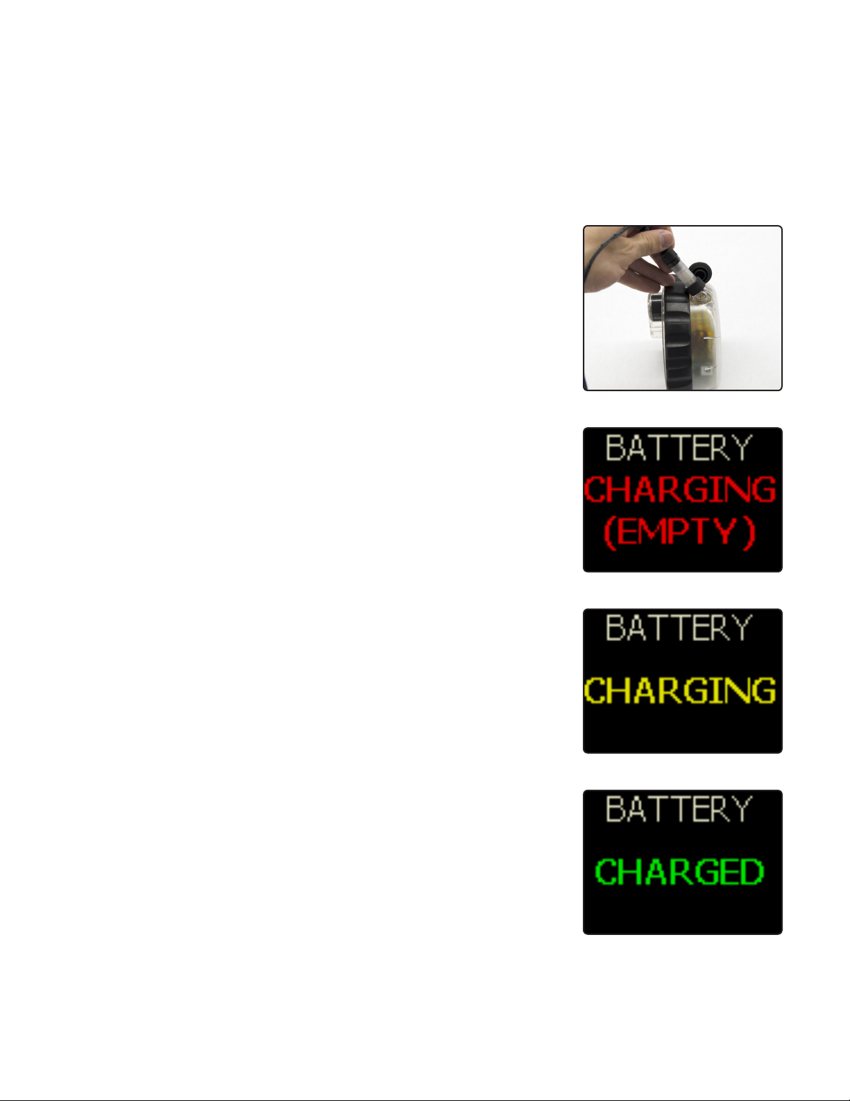
Move the LSS module to one side and peel the Optocon charging/
download connector protection cap off as shown (Fig. 2.5).
Plug in the power charger. You will need to rotate the cable end
connector until the key way aligns. Then push it in and tighten up the
black lock ring. The lock ring will spin freely once the connector is ful-
ly assembled. Once connected and power is applied then a red light
will appear on the Electronic Head.
To remove unscrew the ring (which will rotate freely until pulled back
to start the thread) and pull out the connector.
When charging, a Red light appears on the LSS Module. It turns
Fig. 2.5
Green when the LSS Module if fully charged. A full charge takes ap-
proximately 10 hours.
EXPLORER has 3 battery status displays with the charger connected:
1. Battery Charging (Empty) (Fig. 2.6)
2. Battery Charging (Fig. 2.7)
3. Battery Charged (Fig. 2.8)
Once fully charged the LSS Module can be refitted to the Canister.
Fig. 2.6
Fig. 2.7
Fig. 2.8
12 |
Page 19
To view the charge status of your EXPLORER, do the following:
CC
OC
1. Remove the charger (if attached).
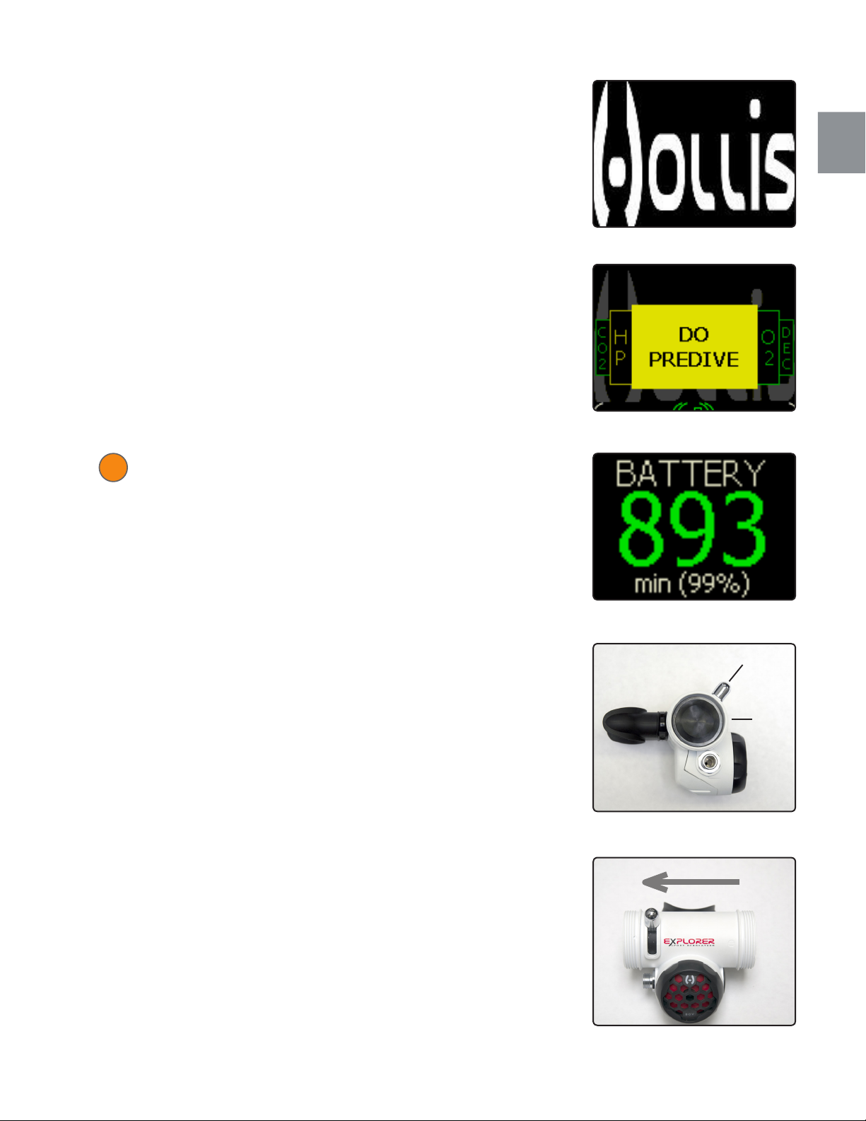
2. Do a long hold of any button on the handset and the Hollis splash
screen (Fig. 2.9) will display. This screen will timeout after 3 seconds
and the "Do Predive" screen (Fig. 2.10) will display.
3. Continue to do a short push of the either button until you see the
central window change to battery status (Fig. 2.11).
WARNING: DO NOT start a dive with a battery minutes display
!
of less than twice the dive time you intend to do. The Pre-dive
sequence will fail if the battery minutes are too low.
2.1
Fig. 2.9
Fig. 2.10
Step 6.
If required attach the BCD to the Case Front using the screws supplied.
Connect the LP inflator hose.
Step 7.
Inspect the mushroom valves in the BOV and make sure they are in place.
Put the BOV into the CC (Closed Circuit) position (Fig. 2.12). Look into one
side of the BOV at the mushroom valve. If you can see daylight through the
other side of the BOV then the valve is not seated correctly.
With the BOV lever in the Closed Circuit position, breathe off the BOV and
ensure the mushroom valves function correctly as per the instructions in
the ‘BOV Assembly’ subsection in the "Complete Disassembly & Reassembly" Part of this manual.
Attach the regulator LP hose to the BOV and gently tighten the nut
to the hose inlet (Fig. 2.13, item C). After inspecting the hose end
O-rings, attach the breathing hoses to the BOV. Ensure the white hose
end goes to the inhale side (Fig. 2.13, item B) of the BOV.
Fig. 2.11
Fig. 2.12
A B
C
Fig. 2.13
| 13
Page 20
Fit the breathing hose alternate ends to the Canister. Ensure the white
hose end goes to the white coded Canister port.
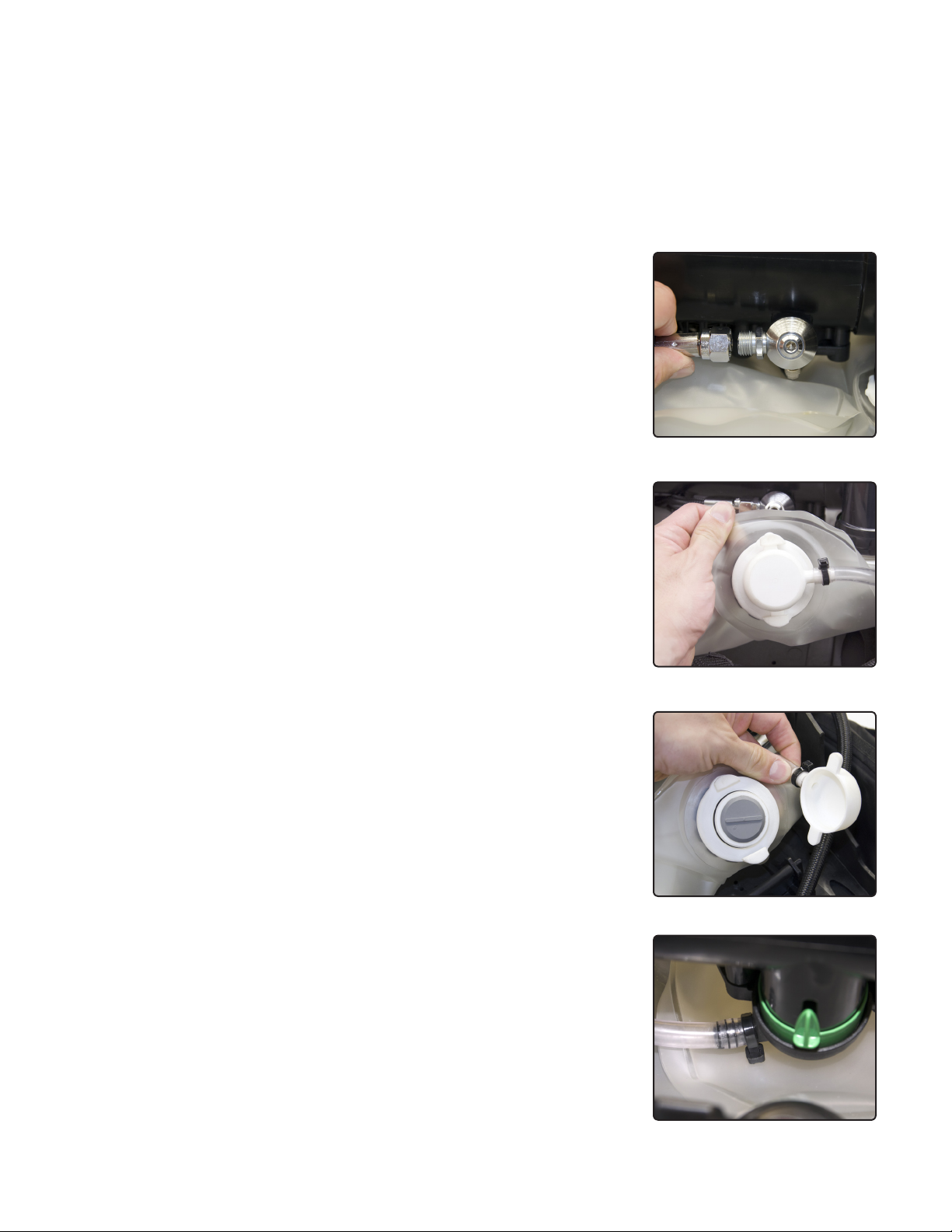
Confirm the ADV LP feed hose is fitted correctly and tightened to a
torque of 50-60 in-lbs/5.6-6.7 N-m (Fig. 2.14).
Step 8.
Remove the Counterlungs from the packaging. Visually inspect them
for damage.
The Exhale counterlung (Fig. 2.15) is the one with the mushroom valve
in the base (this valve is seated in the LCV port).
The LCV port cap is removed by a ¼ turn counterclockwise. This gives
access to the mushroom valve. Inspect the mushroom valve and LCV
Fig. 2.14
port O-ring and the Canister port O-rings for damage (Fig. 2.16).
Attach the LCV port cap to the counterlung. Twist the cap until it clicks
shut.
If not already installed, attach the LCV tube open end to the LCV on the
Canister, using the clip provided (Fig. 2.17).
Fig. 2.15
Fig. 2.16
14 |
Fig. 2.17
Page 21
Inspect the Canister port O-rings on the Inhale counterlung and attach the
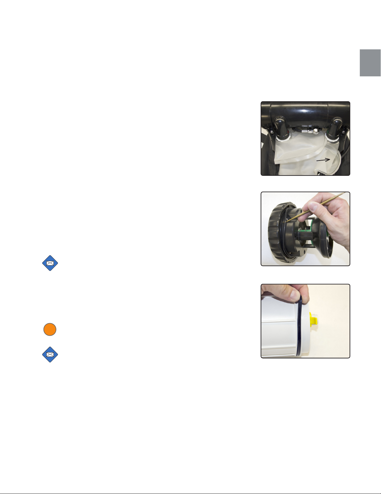
counterlung to the Canister. The assembled orientation of the Counterlungs and the LCV tube should be as shown (Fig. 2.18). The LCV tube is
on the underside of the counter lung in the figure and is not visible.
Step 9.
Remove the Right-hand End Cap by twisting the lock ring ½ turn counterclockwise and visually* inspect the sealing O-ring (Fig. 2.19).
2.1
LCV
EXPLORER can be used with two types of absorbent filter:
• Professionally pre-packed
• Single use Pre-packed
The Professionally pre-packed version can be filled with granular absorbent by a qualified dive professional (see you Instructor or Hollis dealer
for more information).
The Single Use pre-packed version comes in a sealed bag and the filter
CANNOT be taken apart or refilled.
NOTE: If the unit is supplied with a Professionally pre-packed
absorbent Filter then this will be assembled inside the Canister. Reach into the Canister and pull out the Filter by grasping
the central (yellow) pull-tab.
Inspect the Filter quad-ring for damage. Clean the ring groove and the ring
and lightly grease the ring before refitting (Fig. 2.20).
WARNING: This Quad Ring should be replaced every 30 hours
!
of dive time or annually whichever comes sooner.
NOTE: The Single Use Pre-packed Absorbent Filter comes
supplied in a sealed bag and is available from your Hollis deal-
er. This also has a quad ring tted, which must be inspected
prior to use.
Fig. 2.18
Fig. 2.19
Fig. 2.20
For Professionally pre-packed systems, pack the Absorbent Filter as per
instructions.
Insert the scrubber into the canister, and seat it by pressing it into position.
Then refit the end cap by aligning the tab on the end cap and pressing in
* The O-ring pick is used in the photo for illustration purposes. It is not
necessary to remove the O-ring before every dive.
| 15
Page 22
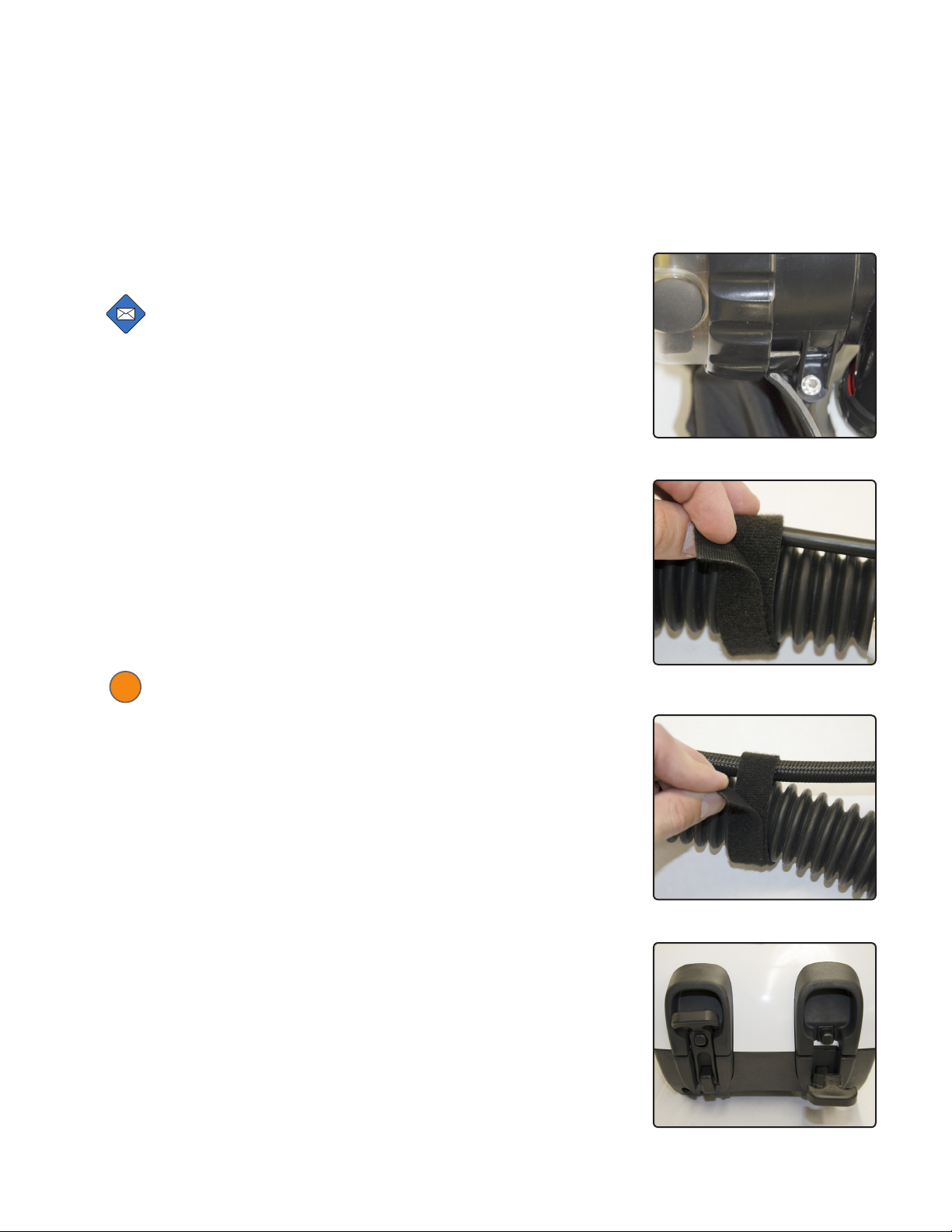
on the clear center. While pressing firmly, twist the lock ring to 3 O’clock
with your fingers until fully closed as shown (Fig. 2.21).
NOTE: The Case Back will not t and lock properly if the end
cap lock rings are not in the correct orientation.
Step 10.
Fit the SCUBA cylinder. Ensure the HP hose fits into the slots in the case
under the cylinder. Tighten the cam strap.
Inspect the HP DIN wheel O-ring for damage and attach the DIN wheel.
Step 11.
Attach the HUD to the HUD bracket and fit the hose wraps as shown (Fig.
2.22).
Fit the LP hose wraps as shown (Fig. 2.23).
Step 12.
Refit the Case Back and secure the two clips at its base (Fig. 2.24).
WARNING: Ensure that the counterlungs are not pinched
!
during installation of the Case Back. Pinching counterlungs
could puncture or cut the counterlungs, leading to ooding and
risk of drowning.
Step 13.
Turn on the wrist display by doing a long hold of either buttons.
Complete the pre-dive sequence as instructed.
Fig. 2.21
Fig. 2.22
16 |
Fig. 2.23
Fig. 2.24
Page 23

Life Support System (computer)
General Operation
The EXPLORER Life-Support System (LSS) is designed around a breathing
loop, high pressure gas sources and electronics control system - all highly
integrated to give an intelligent but simple display of status to the diver
while providing life-support.
This gives the user a simple "Check-and-Dive" functionality that makes the
EXPLORER the easiest Rebreather to prepare for diving, while ensuring
system integrity and improving safety.
It uses intelligent monitoring and design experience to determine the
appropriate tests and checks that the diver needs to perform to get the
EXPLORER ready for use.
Any problems are described clearly on the STATUS screen with the required action.
The integrated system design means that failures or problems with any
part of the system are communicated to the diver, either in pre-dive checks
and procedures, or as data values/graphics or instructions. There is significant background analysis that produces a warning system sensitive to
changes in expected levels, but intelligent enough to not confuse and over
load the diver with information and situations that may be routine during a
dive. These electronic alarms combined with varying levels of mechanical
user controls ensure the LLS is maintained.
3.1
Examples:
• PPO2 changes that may normally cause PPO2 alarms to be triggered are
inhibited if they are of the correct characteristic expected during a descent
or setpoint change.
• There is a significant amount of mechanical design required to achieve
a moisture tolerant breathing loop that reduces distortion of the readings
from the PPO2/CO2 sensors to a minimum. The reliability of the PPO2
readings is further improved by employing a voting algorithm for the PPO2
sensors that can ignore data from rogue sensors.
The EXPLORER design is simple to use but this simplicity does not mean
that the system is simple in terms of data processing or control analysis.
The EXPLORER includes many levels of warning and system analysis,
simplified through experience and intelligence to provide a straightforward
human interface that does not routinely overload or annoy with status or
| 17
Page 24

false warnings.
It takes considerable system intelligence and design experience to ensure
the warnings do not overload or falsely advise the user of problems. If
falsely warned too many times, then there is a reduced likelihood of the
diver responding correctly to a truly dangerous and potentially life-threatening situation.
Mechanically it is vital that simple mechanical tasks required to set up the
EXPLORER are not ambiguous and prone to user error.
THE HEADS UP DISPLAY
The Heads Up Display (HUD) is an ergonomic addition for the diver, as it
gives a simplified and quick to follow view of the status of the EXPLORER.
The HUD as 3 main warning levels:
• Flashing Red plus vibration alarm - warning is activated when a dive
should be aborted on open circuit or not started.
• If diving, the diver should switch to the bailout gas.
• The HUD vibration alarm will vibrate every ¼ second for 10 seconds, and
then repeat the 10-second alarm every minute.
• Flashing Green and Blue Leeds - warning is activated when a manageable error situation is in place. The correct response is to ascend slowly on
closed circuit monitoring the Primary display.
• Solid Green - means there are no detected problems
WARNING: If any other light sequence or a ‘no light’ scenario is
!
experienced then the diver should refer to the wrist display for
information.
WARNING: If no wrist display is seen the diver MUST switch to
!
open circuit and ascend.
The LED states are configured for color blind as well as highly stressed divers. The positions of the LED’s, the flashing or solid state, provide conditions that cannot be confused with one another. Also, during stressful dive
scenarios, the position and status is quick to comprehend and therefore
intuitively the desired response is performed.
18 |
Page 25
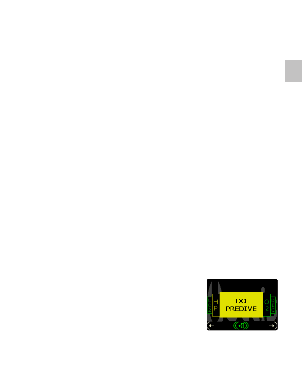
PRE-DIVE CHECKS
With current technology, not all aspects of the safety and working nature
of the EXPLORER system can be performed or determined automatically.
Therefore, when turning on the EXPLORER, there are a series of pre-dive
checks that must be performed. The EXPLORER also gives guidance in
performing these checks. These checks are displayed in sequence on the
EXPLORER wrist display unit. Some of these checks rely completely on
the diver to perform them correctly – i.e. Close/open mouthpiece. Other
tests can be positively checked for by the electronics control system and
the user needs to confirm that these are OK to dive with – i.e. that the high
pressure cylinder is adequately filled.
Information regarding the current status of EXPLORER and all available
resources can be reviewed prior to conducting Pre-Dive Checks using the
STATUS screen.
DATA LOGGING
EXPLORER has a sophisticated data logging system that not only records
all the units’ sensors (depth, time, PO2; etc.) but also records any alarms
and error messages (such as missed Pre-dive checks). This information
can be retrieved through the data download software and is available in
detailed form to Hollis Service Technicians.
3.1
Users can obtain dive download software from http://hollis.com/support.
asp.
STATUS SCREEN
The EXPLORER has two levels of detailed information available to the diver.
The primary method is via the STATUS screen. There is an additional set of
STATUS screens in service mode, described in the section 6 of this chapter.
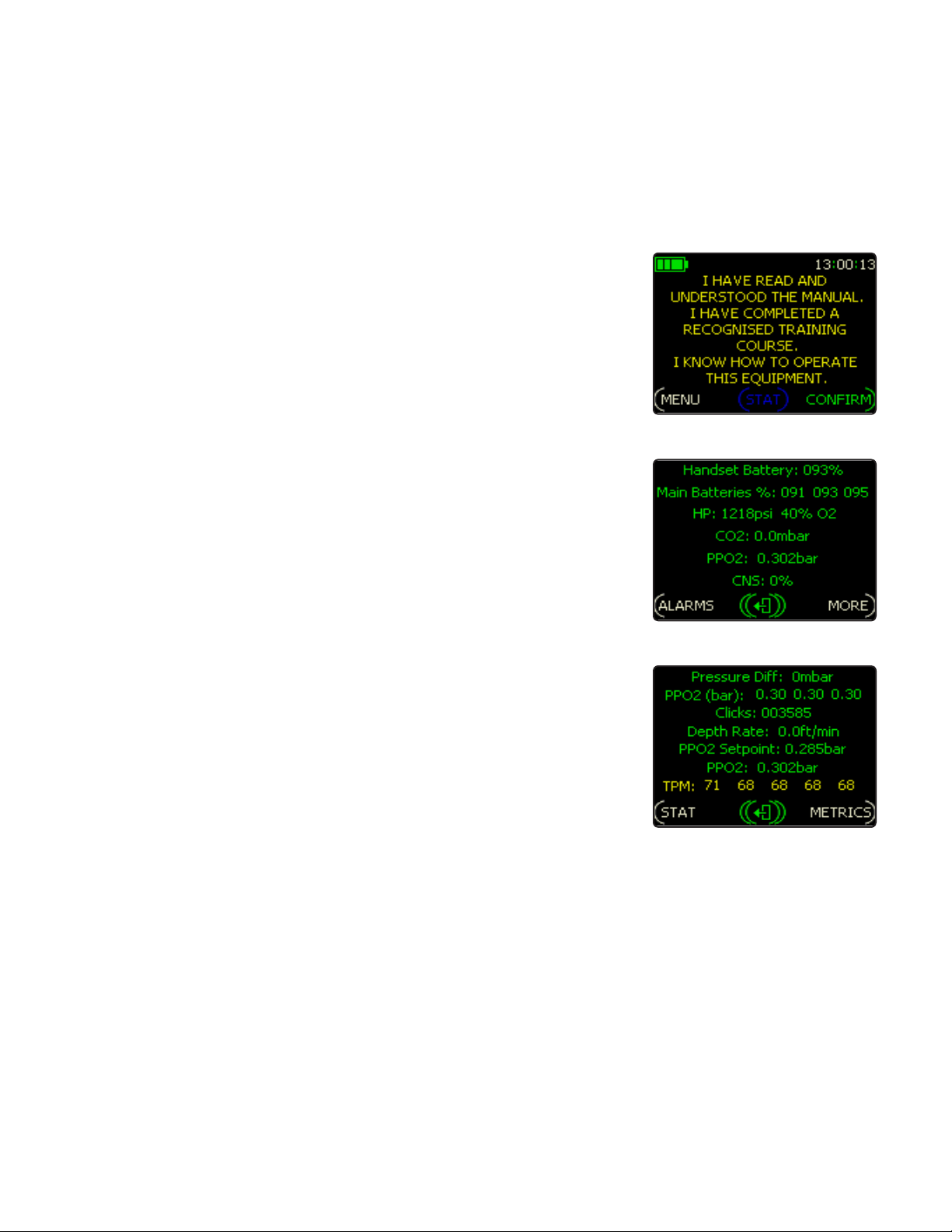
The STATUS screen shows as soon as the EXPLORER is turned on (Fig.
3.1).
Fig. 3.1
| 19
Page 26
In addition, it can be viewed at any point on the dive by pressing any
button and selecting STAT from the pop-up menu using a short push of the
right button. It can also be accessed in service mode by selecting STAT (a
short push of both buttons) from the Startup screen. Note that in both cases the STAT button indication is colored blue, as are all button indicators
modified by service mode.
Once in the STATUS screen, a short press of the left or right button scrolls
round the information options. These are:
a. PPO2 (average of the 3 sensors)
b. CO2 sensor
c. HP gas
d. Battery life
e. No Decompression Limit (NDL)
f. Decompression Information
g. Filter (CO2 filter)
h. CNS
i. A general Warnings Window (the ACTION Panel) detailing any alarm in
progress. This mostly displays ‘SYSTEM OK’ or ‘DO PREDIVE as in the
above example unless there is another fault to report.
SERVICE MODE
Fig. 3.2
Fig. 3.3
Service mode is accessed in the Setup Menu.
With this mode set, each pre-dive screen shows additional text information
relevant to the test being performed.
Also, it enables an extra (blue) STAT button on the Startup screen (Fig.
3.2), which if selected with a long push of both buttons (not indicated), will
allow access to detailed service sub-screens. Your Hollis dealer will use
information on these screens to assist with any servicing required. A short
push of STAT will just display the STATUS screen and relevant resources
as during a dive.
To enable fault diagnosis put the EXPLORER into Service Mode. Having selected STAT with a long hold of both buttons from the Startup screen you
will access two extra screens (Fig. 3.3, 3.4) (plus alarm and metric screens,
not shown).
20 |
Fig. 3.4
Page 27
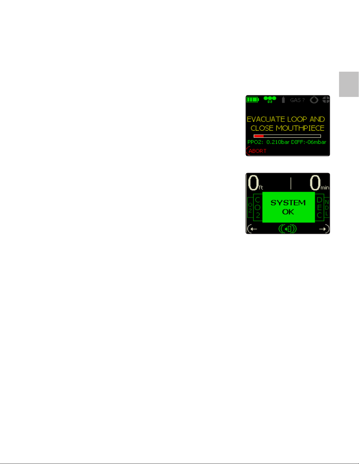
During Pre-dive additional information will be displayed on each Pre-dive
screen such as the PO2 and internal loop pressure (Fig. 3.5).
Your Hollis dealer may need access to this information to help with any
issues. Please see the separate EXPLORER Service Manual for details.
STATUS SCREEN COLORS
3.1
There are four color states of the STATUS screen. Each color provides
additional information. The four color states are:
Green - No problem with the information
Yellow - The system is informing you of a low level alarm such as low
HP gas supply. The STATUS Screen’s Action Panel will give information
regarding the warning or action to be taken and in the case of the low HP
gas example, the value in the HP window will also be in yellow. This will
result in a flashing Green/Blue HUD
Magenta - indicates unreliable data on the reading being taken. This could
be caused by a failed sensor (such as a low wireless HP battery). This will
be coupled with an action to be taken displayed on the STATUS Screen’s
Action Panel. This will result in a flashing green/blue or red.
Red - A major alarm Indicating that information/resource has now become
critical forcing, an open circuit bailout. OC Bailout will be displayed on the
STATUS Screen’s Action Panel and the HUD will flash red and a vibrating
alarm will sound in the mouthpiece
From the Main Dive Screen a double press of the right button will bring up
the STATUS screen (Fig. 3.6) so that the user can determine at a glance
the status of the system while doing a check. This can be useful to determine why a check is not working correctly.
Fig. 3.5
Fig. 3.6
| 21
Page 28

AUTOMATIC TURN ON
FAILSAFE FEATURE
Normal practice and training is for the user to turn the EXPLORER on byhand and go through the pre-dive checks. The following failsafe additions
are to reduce diver error, where the EXPLORER is turned off prior to breathing on the unit. The basis for the auto-breathe software is to reduce the
chance of accidental injury or death by breathing on an EXPLORER that is
in off/sleeping state.
EXPLORER uses detection of a diver breathing the unit to automatically
turn the unit on.
BREATHING DETECTION TURN ON RULES
The EXPLORER will turn on if PPO2 drops to 0.17bar. Therefore even with
the unit incorrectly assembled (gas not turned on), the system will detect
the fall in PPO2 and will activate. It will then alarm and force the user to
properly complete the pre-dive sequence.
Once turned on the unit will attempt to maintain a breathable PPO2 based
on the DCP (Dive Control Parameter) setting and the supply gas expected.
If sensors are removed or read 0.00 then the unit will only turn on with
depth or by the user pressing a switch. This feature is included to conserve
battery power when the user takes out PPO2 sensors for storage or during
transport. Other current rebreather designs and CE approvals require a
reduced safety margin than achieved even with this power save scenario.
In other words, the chance of the user taking out the sensors and accidentally not turning the unit on before breathing falls into user set-up error that
should not routinely occur due to training and a good pre-dive check regime. Other errors such as failing to turn on cylinders, etc. are much more
likely, and should be reduced by proper training and the intelligent alarm
systems as in the EXPLORER.
If the diver does not have HP gas turned on, alarms on the HUD (forwards
and rear facing HUD) and Primary display will occur as soon as auto turnon occurs. Hence this method provides increased warnings whenever loop
PPO2 is breathed when the unit is off.
22 |
Page 29
Breathing the loop, in all circumstances where the unit is breathable and
PPO2 sensors operative, will cause a safe turn-on.
!
DANGER: The additional safety features described in this
section should NEVER be used as routine. The user should
ALWAYS turn on the unit and pre-dive checks carried out as
required in training and the operations manual.
3.2
| 23
Page 30
3.3
Display Symbols
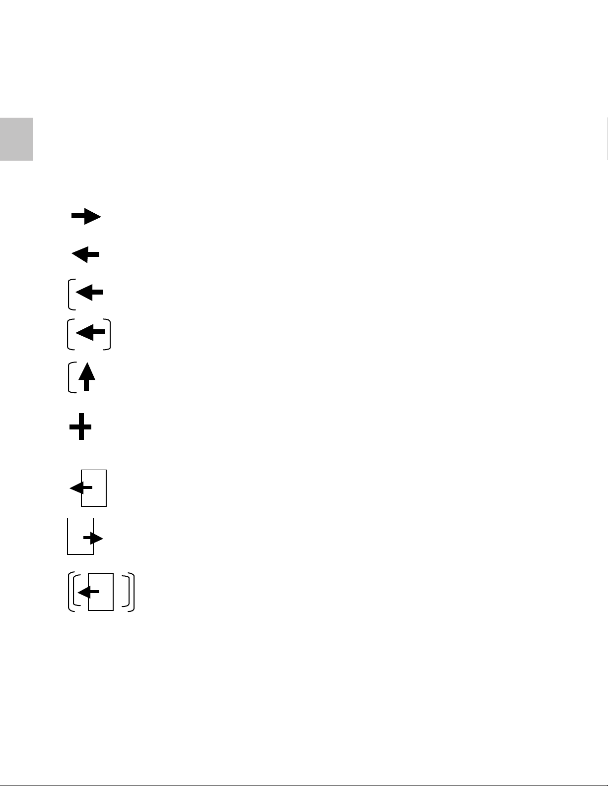
Most screen commands (soft buttons) are actually the written word (in
English) but movement commands are expressed using icons.
Moves the cursor to the next field to the right to edit or
moves the STATUS display one window to the right.
Moves the cursor to the next field to the left to edit or moves the
STATUS display one window to the left.
A single bracket indicates a short push of the button to perform
the action (in this case move left)
A double bracket indicates a short push of both buttons to
perform the action (in this case move to left)
Moves the cursor up to the next option (as in a menu list). In this
case a short push of the left button. A down arrow moves the
cursor down.
A short push increments the information by 1 digit. A long push
increments the information in multiples. A minus sign (-)
decrements the digit.
EXITS to the previous page and SAVES the information.
ENTERS the selected item/page
A double bracket around a function indicates a long push
of both buttons. In this case to exit the page.
24 |
Page 31
SCREEN ICONS
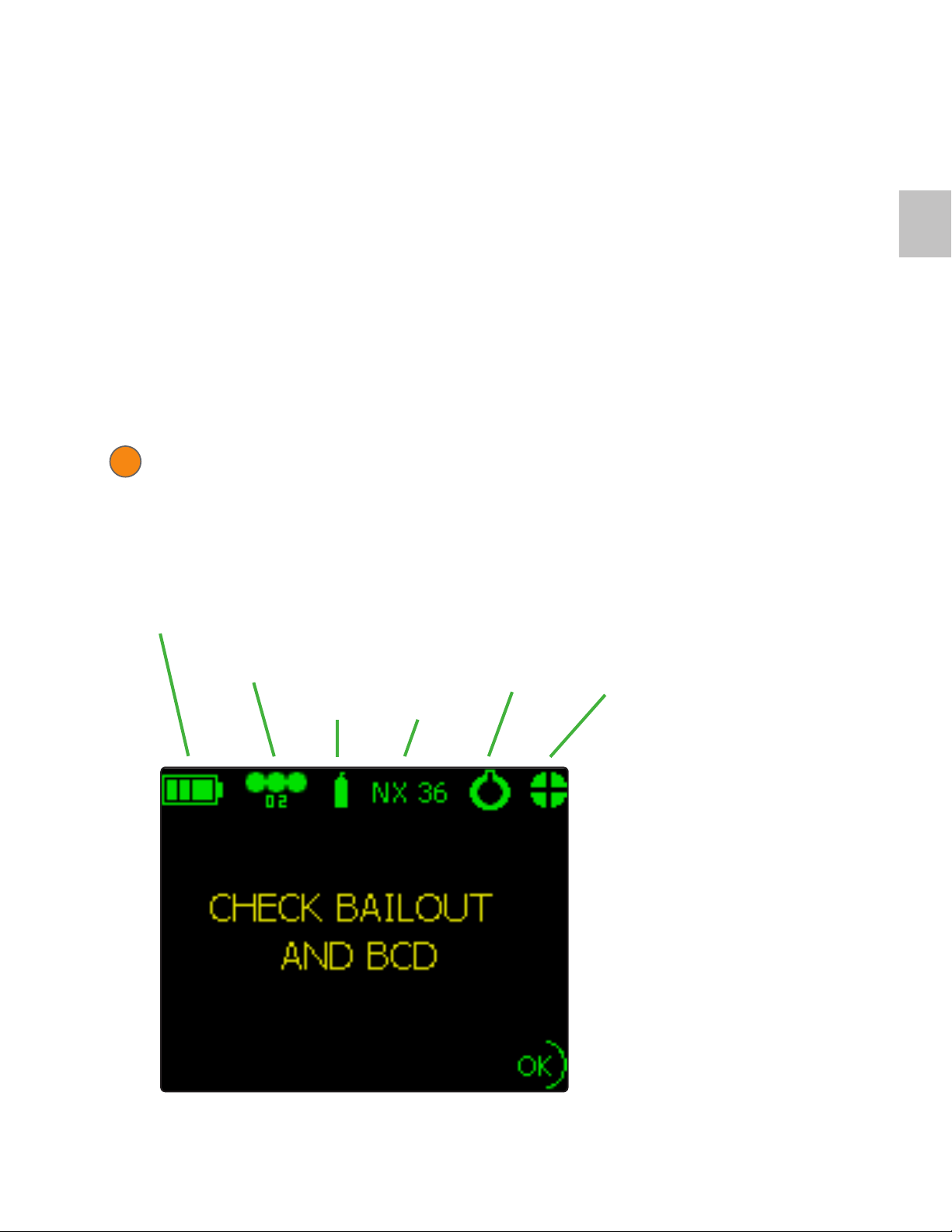
During the Pre-dive tests icons appear across the top of the screen starting
on the left.
As each level of Pre-dive is completed successfully a green icon appears
indicating the test has passed successfully.
Note that all icon colors, as with any numerical displays, match the alarm
severity – yellow indicates a blue/green HUD state. In addition, a grey icon
indicates a test not yet performed.
WARNING. A red icon means a failure of the test/alarm which if
!
ignored would make EXPLORER unsafe to dive.
The icons are:
3.4
Battery &
Computer
O2
Sensors
HP Gas
Content
HP Gas
Analysis
Breathing
Loop
CO2 Removal
System
| 25
Page 32
3.5
DIVE SCREENS
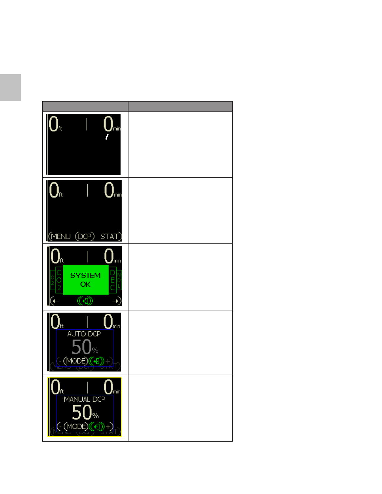
Screen Description
Dive
Time
Dive Screen
(when ascent rate bar is ½ full then
rate is 30 ft/min
10 m/min)
Dive Screen with menu bar
(accessed by a single push of any
button)
Status Screen
(accessed by a short double push
of the right button)
DCP Auto Mode
(short push of both buttons to
change modes)
DCP Manual Mode
(short push both buttons to change
modes, 1% increment change by
short push of either button, 10%
increment change by long push of
either button)
26 |
Page 33
status screens
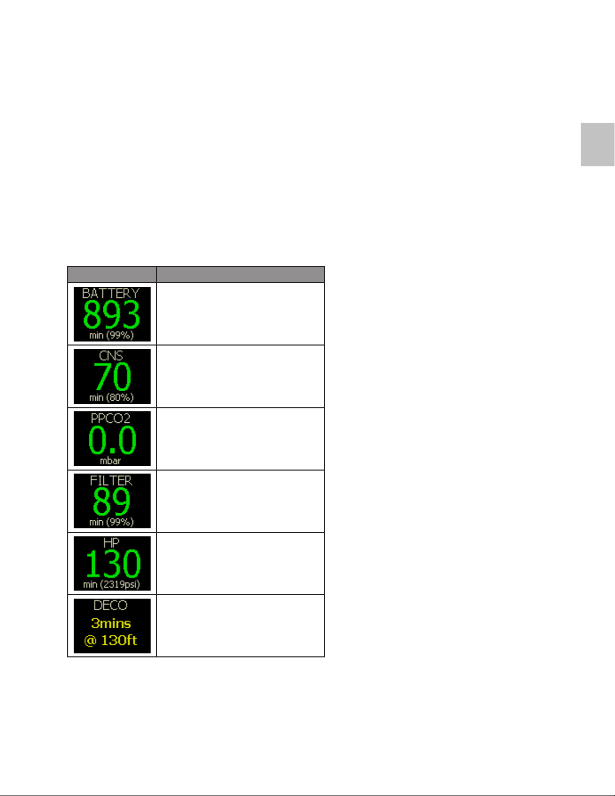
The Status (STAT) screens show all key resources in a simple format.
The screen is accessed from the main screen by a short double push of
the right button, and then a short push of either the left or the right button
moves around the screen. The Status screen also incorporates a color
coded Action Panel to give instructions.
The items that can be displayed are:
Screen Description
Battery time in minutes
CNS oxygen toxicity time in minutes
3.6
Partial pressure of carbon dioxide
in millibars
Carbon dioxide absorbent filter
estimated remaining time
High pressure nitrox gas supply
remaining in minutes, at current
depth and workload
Any decompression information
NOTE: The Status screen disappears after 5 seconds of inactivity (if no alarms) or 30 seconds if an alarm is present. Alter-
natively a long press of both buttons will ‘Hide’ the screen.
| 27
Page 34
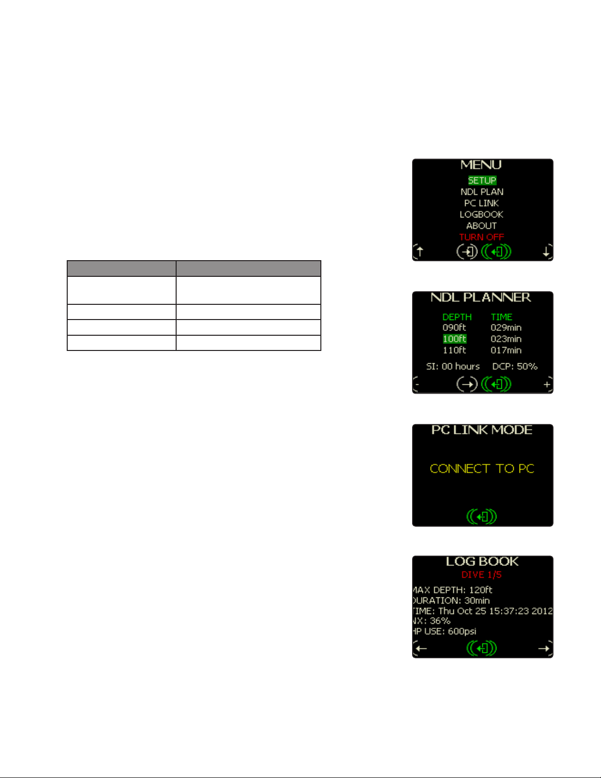
MAIN MENU
MAIN MENU SCREEN (FIG. 3.7)
The EXPLORER has a simple menu system which is available while at the
surface. To access the Main Menu short press any button.
MENU NAVIGATION
Action Button Press
Enter Highlighted
Short push both buttons
Menu Item
Exit Long push both buttons
Scroll Down
Scroll Up
Short push right button
short push left button
MAIN MENU OPTIONS
SETUP
Setup is a basic settings menu. See the following Setup Menu section for
further details.
NDL PLAN
It is a dive planner based on current tissue state, surface interval, and a
DCP setting for the next dive (Fig. 3.8).
PC LINK
Fig. 3.7
Fig. 3.8
Fig. 3.9
This screen is a gateway to updating the internal software and downloading the log information to a PC (Fig. 3.9). Further details can be found in
the Internet Reprogramming section of this manual.
LOGBOOK
The Log Book screen is where you access recorded information on previously completed dives (Fig. 3.10).
28 |
Fig. 3.10
Page 35
ABOUT
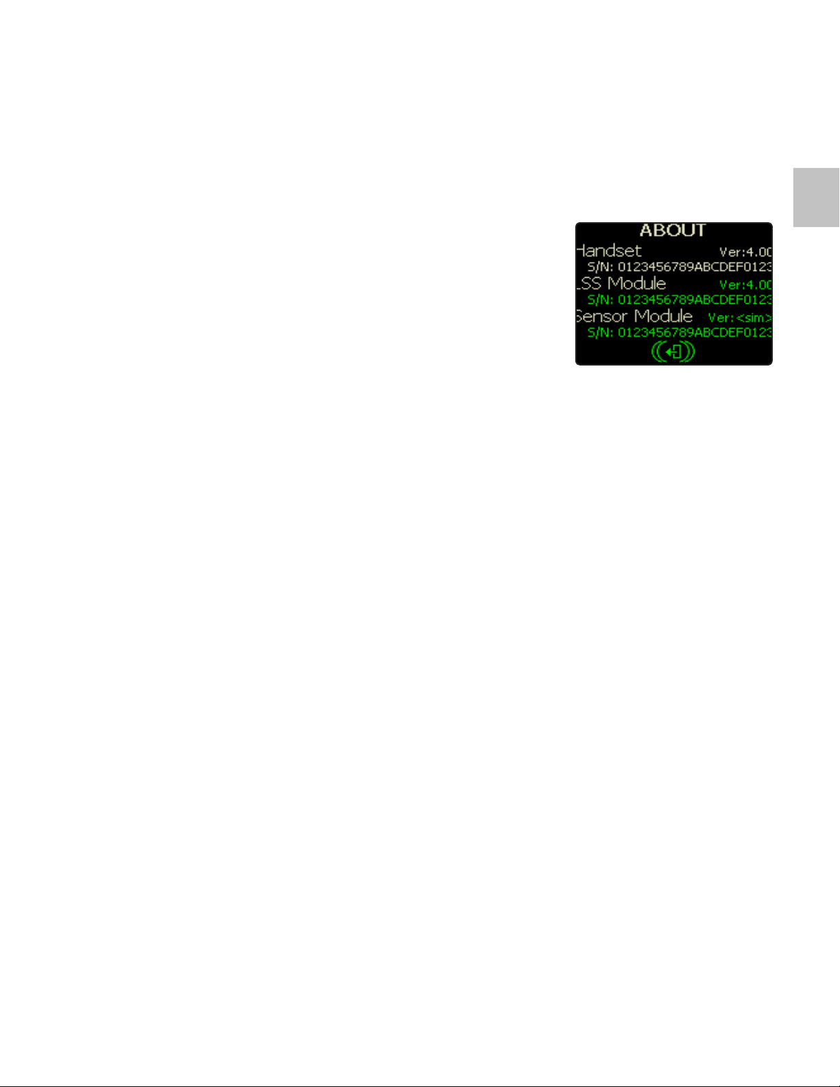
This screen shows information about the software installed in the EXPLORER, the serial number of each connected element, and information that
may be required by your service center. Software updates for the EXPLORER are available from http://hollis.com/support.asp. Please check regularly for updates. Once a new update has been installed, this screen will
report the new version of software installed (Fig. 3.11).
3.7
TURN OFF
This selection shuts down the Explorer electronics.
Fig. 3.11
| 29
Page 36
setup menu
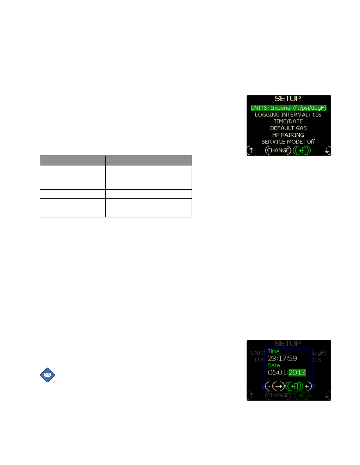
MAIN MENU SCREEN (FIG. 3.12)
The EXPLORER has a simple menu system which is available while at the
surface. To access the Main Menu short press any button.
MENU NAVIGATION
Action Button Press
To Make A Change
Short push both buttons
(enter the modification
screen)
Exit The Menu Long push both buttons
Scroll Down
Scroll Up
Short push right button
short push left button
SETUP MENU OPTIONS
UNITS
This option allows for the switching between metric and empirial unit
modes.
LOGGING INTERVAL
This option allows for the selection of how frequently the computer takes
a snapshot of dive data, stored for later download. Using a shorter interval
results in more data points per dive and fewer stored dives for download
data respectively. Longer data intervals result in fewer data points (less
detail) but the space to store more dives.
Fig. 3.12
TIME/DATE
This is the clock and calendar setting (Fig. 3.13).
NOTE: When the EXPLORER is rst powered up from a at
battery you will be asked to update the date and time.
30 |
Fig. 3.13
Page 37
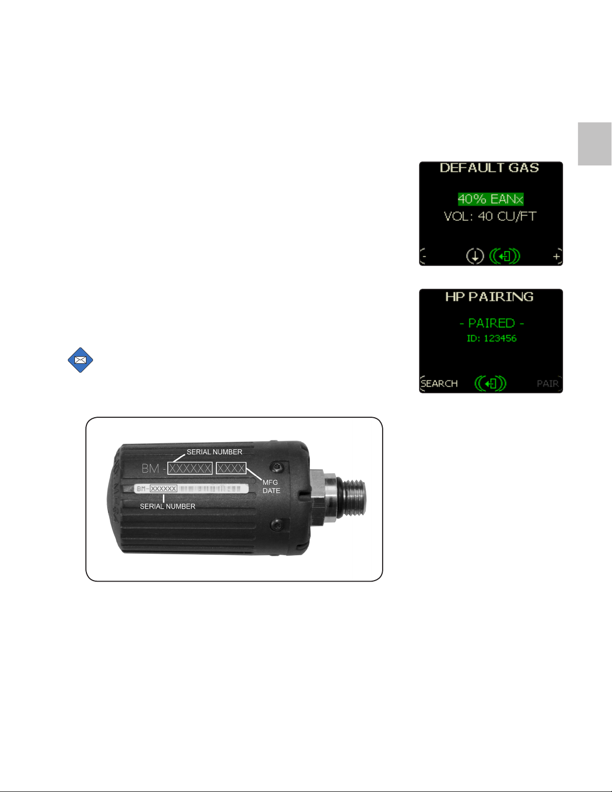
DEFAULT GAS (FIG. 3.14)
Set this to your normal dive gas. During the Pre-dive if EXPLORER analyzes a different gas, it will alarm and ask you to recheck the analysis. For
further detail on proper use of this function see the following section "Bailout and Gas Configuration".
HP PAIRING
3.8
To pair the HP transmitter, first press SEARCH, any transmitters in range
will be displayed. Then press PAIR. The word PAIRED will appear once the
transmitter is recognised (Fig. 3.15). The transmitter ID is written on the
transmitter attached to the first stage in your EXPLORER (Fig. 3.16). Please
confirm this is the correct transmitter.
NOTE: The HP transmitter MUST have pressure applied to it
to activate and be seen by the system. If the regulator is not
pressurized the the transmitter will be off and not sending a
signal.
Fig. 3.14
Fig. 3.15
Fig. 3.16
SERVICE MODE
Service Mode allows access to more detailed information about the
EXPLORER. It can be accessed by your Dealer. A separate Service
Manual is available through www.HollisGear.com.
| 31
Page 38
3.9
Bailout and Gas Configuration
DEFAULT GAS SETTING
The EXPLORER has the capability to analyze the dive gas attached to the
system. If this gas differs significantly from what the EXPLORER expects
(the programmed Default Gas), then a warning will be given during the predive sequence. This is to help protect against absent or faulty gas analysis
by the gas supplier and user.
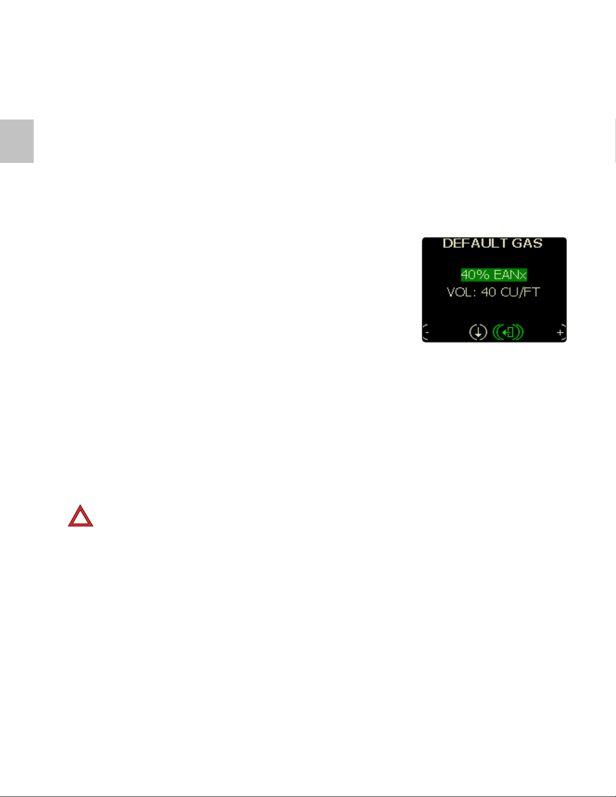
To change the Default Gas, when the unit turns on, go to the SETUP menu
screen and highlight Default Gas by repeated short presses, then a short
push of both left and right buttons to select (Fig. 3.17). The gas can now
be set.
The Default Gas information is used to drive bailout gas calculation (using
cylinder size) and hence gas time remaining and when the unit performs
its gas analysis checks, if the gas analyzed is not the default gas then a
warning will display to prompt you to re-analyze the gas or calibrate the
oxygen sensors.
Fig. 3.17
If the analyzed gas is not what you expected (the Default gas) but is still
usable you can simply start the dive without having to change the Default
gas but you must change the cylinder size if it is incorrect. If the analyzed
gas is lower than expected (within 5%), then it will replace the gas used,
else the default gas will be used.
On this screen you can also input the cylinder size.
!
DANGER: It is important that the correct cylinder size is entered for EXPLORER to correctly calculate the remaining
resource times.
BAILOUT GAS
It is not necessary to set a bailout gas. Whether the bailout is undertaken on the onboard (attached) gas or on an external gas supply, the
EXPLORER assumes 21% oxygen and 79% nitrogen as the bailout
gas. This is to ensure as safe an ascent as possible in an emergency. All
bailout decompression calculations are based on 21% oxygen and 79%
nitrogen.
32 |
Page 39
DCP (Dive Control Parameter)
3.10
DYNAMIC PO
2
The EXPLORER is a dynamic PO2 controller. This means it can vary the
PO2 that it maintains based on the value of certain resources. A higher
DCP (Dive Control Parameter) value means less decompression (higher
PO2) but more gas usage and a lower PO2 is the opposite. For a set DCP
the actual PO2 will vary throughout the dive profile.
The DCP can be set to AUTO or MANUAL mode.
MANUAL MODE
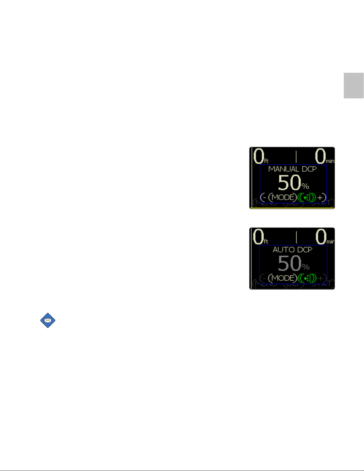
In manual mode the diver can set the DCP using the screen shown (Fig.
3.16). A long hold of either the + or - button will jump the DCP value by 10.
AUTO MODE
AUTO mode automatically adjusts the DCP throughout the dive to give the
best compromise between maximum NDL and minimum gas usage (Fig.
3.19). While shallow (less than 10 m), the DCP will remain at its current value. This defaults to 50% each time the unit is switched on. The first time the
dive exceeds 10 m depth, the DCP will automatically be set high to reduce
the NDL but then as the diver ascends and the NDL naturally increases,
then the DCP will start to automatically reduce to save gas while maintaining a long NDL (>1 hr). At the start of the dive the DCP will automatically
set high to reduce the NDL but then as the diver ascends and the NDL
naturally increases, then the DCP will start to automatically reduce to save
gas while maintaining a long NDL (>1 hr)
Fig. 3.18
Fig. 3.19
NOTE: Auto Mode is the default. If on a dive where Manual
Mode has been selected and you then surface and complete
the dive, Auto Mode will be the default at the start of the next
dive.
HOW AUTO MODE WORKS
By setting ‘Auto’ DCP prior to diving the following events occur.
1. The DCP will automatically be set to 95% for the first 10 minutes of the
dive but only after the diver exceeds 10 m of depth.
| 33
Page 40
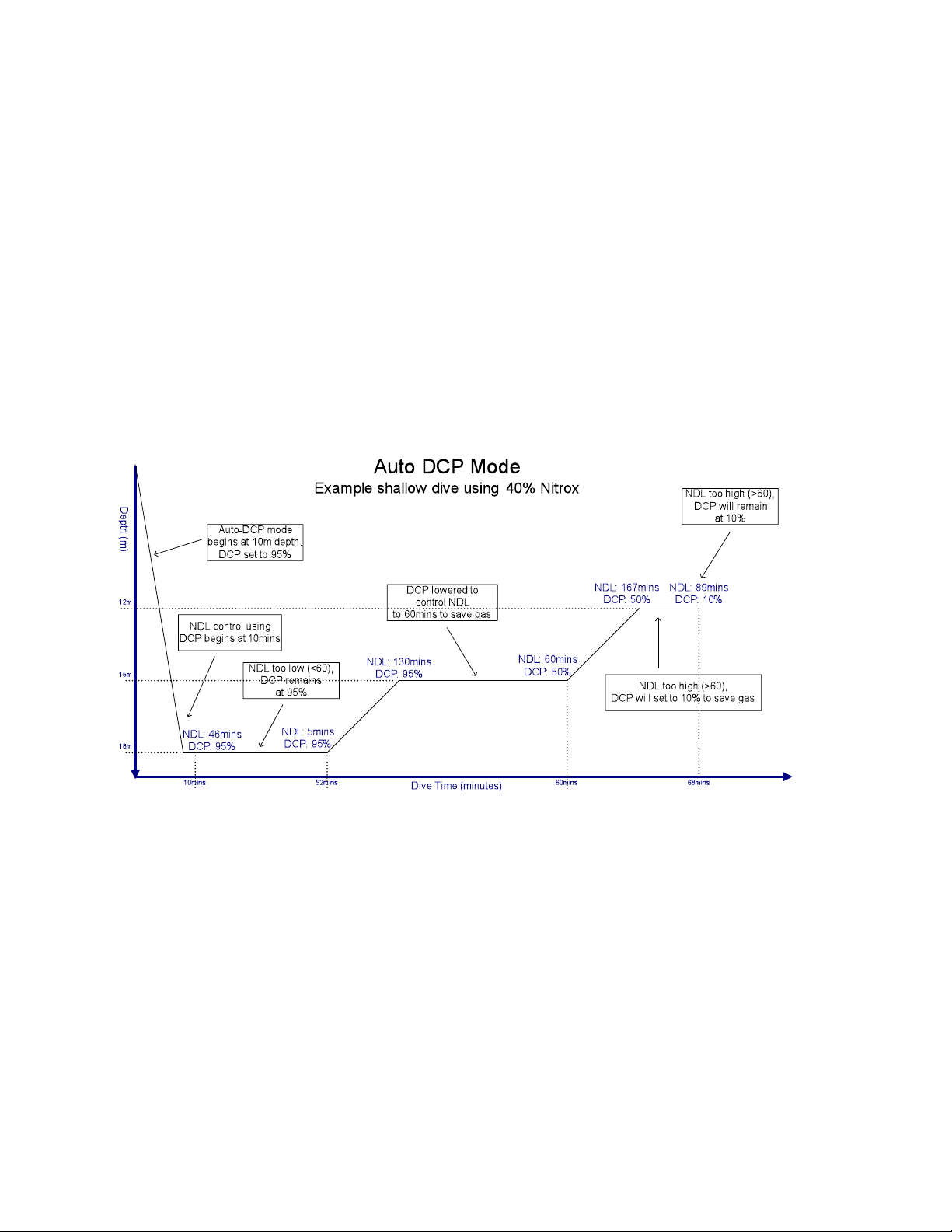
2. If the NDL is then less than 60 minutes the DCP will stay set to 95% to
maximize the NDL.
3. If at any point on the ascent the NDL is in excess of 60 minutes then the
DCP will reduce to save gas and maintain the NDL at 60 minutes.
4. The minimum DCP will only go to 105 so if a dive profile means that
even with 10% the NDL is greater than 60 minutes then the DCP will stay at
10%.
34 |
Page 41
RMS (Resources Management System)
The control of PPO2 is the prime function for EXPLORER in addition it
monitors a range of dive resources. The unit is able to make advanced
decisions based on available resources in order to modify the PPO2 and
provide for a better dive outcome.
The unit constantly monitors all resources such as available gas, filter
duration, etc. and keeps the dive within parameters that allows for a safe
bailout ascent. The unit uses a forward-looking algorithm to determine
the best PPO2 at any given time to avoid or reduce decompression, allow
for a safe open circuit ascent and stay within safe battery and filter durations.
Resources monitored include;
• Depth
• NDL
• PPO
2
• PCO
2
• Battery
• HP gas
• CNS (Oxygen toxicity)
• Filter (CO2 filter)
Fig. 3.20
3.11
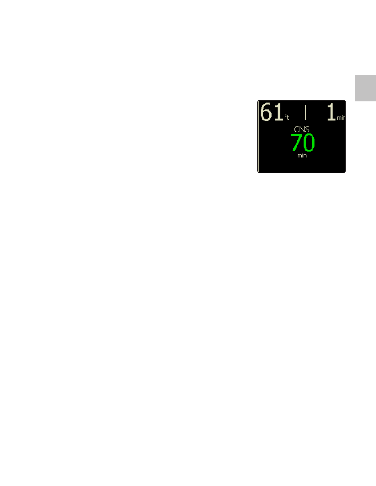
Resources are generally expressed in minutes and are noted in the center of the dive screen (Fig. 3.20).
The controlling (most critical) resource is shown. This can change
throughout the dive and another resource may take its place. Alarms will
be activated when resources reach certain levels as defined in the Alarm
Tables.
In addition, should a resource alarm be triggered for any reason occur
the STATUS screen will appear. This will not only note the resource level
but can also tell the user the direct action required, i.e. ASCEND NOW.
| 35
Page 42

Oxygen Sensor Calibration
The EXPLORER is able to perform accurate calibration of the Partial Pressure Oxygen (PPO2) sensors in ambient air. This has particular importance
on the ease and accuracy of achieving calibrated sensors.
The EXPLORER is able to measure atmospheric pressure during calibration and make the appropriate calibration adjustments for the sensors,
even at altitude. When performing sensor calibrations, it is important that
the calibration gas and ambient pressure are known. By using ambient air
as the calibration gas this is known accurately.
Calibraon Errors
When Oxygen sensors are new or completely dry and a
calibraon is undertaken, a small dierence will be not-
ed when another calibraon is done aer a dive. This is
because the humidity inside a unit post-dive aects the
sensor membranes permeability to a small (safe) degree.
In general, it is good pracce to calibrate a unit in an
as-dived state i.e. with humidity in the loop. This is per-
formed naturally during the Pre-Dive Check sequence.
The EXPLORER uses advanced empirical techniques to ensure the accuracy of the ambient air calibration.
WARNING: When retting an oxygen sensor or after calibration
of the sensors, a full Pre-Dive sequence MUST be completed.
The user can cause the largest error in oxygen sensor calibration. If the
calibration is not done in ambient air, the sensors will not give the correct
readings after calibration. Therefore do not execute a manual calibration
without ensuring the sensors are exposed to air at ambient pressure.
The units testing for good and bad oxygen sensor calibration is determined from the sensor mV level detected during calibration. At 1000mBar
atmospheric pressure the range the unit can calibrate for is approximately
5mV to 15mV. However, if a sensor that would normally show 7.5mV in air
has an enriched gas applied to it of 40%Oxygen during calibration, then
the sensor will give 14.28mV, and the calibration will pass, but the sensor
will be reading only about half of the actual ambient Oxygen.
36 |
Page 43
Recommendaons
• Never store sensors for long periods of me before
use; they have expiraon dates.
• Never subject sensors to high temperatures i.e. (inside
cars, garages etc.).
• Never freeze sensors (le in cars overnight).
• Never subject sensors to physical shocks.
• Never subject sensors to vacuum
• Never submerge sensors in liquids.
• Never aempt to open a sensor. They contain a causc
chemical.
• Sensors deteriorate very slowly and near the end of
their useful life may show a dri soon aer calibraon.
• The oxygen sensors are not covered by the warranty,
they must be replaced every 12months or at their ‘do
not use aer’ date or sooner depending on the pp02
they are stored in and the hours of use
• Oxygen sensor usage temperatures are:
- Operang temperature range 0 – 40 °C / 32 - 104 °F
- Storage temperature -20 to +50 °C / -4 - 122 °F
- Recommended storage temperature +5 to +15 °C / 41
°C to 59 °C
3.12
!
DANGER: Always be careful when doing manual calibrations,
AIR must be exposed to the sensors and NO OTHER GAS.
Calibrations should be conducted routinely. However prior to starting
a dive sequence it is advisable to check the oxygen and CO2 sensor
calibration by opening the EXPLORER Module and removing it and
the Sensor Module, place them together (Fig. x.x) and turn the unit on.
Then go to the STATUS screen and view the PPO2 and CO2. If the PO2
is not 0.21 and the CO2 is not 0.3-0.4mb for the CO2, then a calibration
must be performed.
| 37
Page 44

In general, Oxygen and CO2 sensors do not drift excessively. Constant calibration (every dive) is not required. Periodically check sensors and keep
them dry between dives if possible and especially during storage.
WARNING: Use calibration sparingly, not as a routine task that
!
may mask other potential problems.
CONDUCTING AN O2 SENSOR CALIBRATION
During the Pre-dive sequence you have the option to calibrate the oxygen
and CO2 sensors from the Calibration screen (Fig. x.x). Selecting O2, will
display another series of screens that will guide you through the calibration. Please see descriptions later in the manual for calibrating the CO2
sensor.
SUMMARY OF DO’S AND DON’TS
OF OXYGEN SENSOR CALIBRATION
When calibrang sensors there are two factors that the EXPLORER takes into account:
1. Ambient pressure
2. Ambient AIR oxygen content
These two factors mulply to determine the paral pressure of
the oxygen exposed to the Oxygen sensor.
Example:
20.9% oxygen at 1000mBar = 0.209mBar paral pressure of
oxygen
20.9% oxygen at 750mBar = 15.675 mbar paral pressure of
oxygen
The EXPLORER uses ambient air as the calibrang gas, because
its composion is accurately known. This is in contrast to say a
cylinder of compressed oxygen that can vary from supplier to
supplier, as well as around the world, from at least 94% to 100%.
38 |
Page 45

To achieve a good calibraon some basic rules must be observed:
1. The Oxygen sensors must be exposed to the pure calibrang
gas. So for an air calibraon, the sensors must be ushed with
air. Just taking the hoses o is NOT sucient, as pockets of gas
can be enveloping the sensors.
2. DO NOT rounely execute calibraons to remedy a rebreather that seems to be showing the wrong PPO2. If the rebreather
had previously been accurately displaying PPO2, then some other problem is likely to be the cause. These include:
• Oxygen sensors have become wet
• Current gas exposed to the Oxygen sensors is not what you
think it is.
• The min-jack connecon is corroded
Check the readings on the STATUS screen (average) or Service
Mode STATUS Screen (all 3 sensors).
3.12
If a sensor is reading incorrectly, rst remove it and clean the
mini-jack connector. This can be done with Hollis approved electrical contact cleaner or simply by wiping the connector with
a lint free cloth. DO NOT scratch the connector with a metal
instrument. Then look for droplets of moisture on the sensor
membrane. Use a rolled ssue to gently wick any moisture droplets from the sensor WITHOUT making contact with the sensor
membrane itself. Pushing on the sensor membrane face can
destroy the sensor.
If neither of these corrects the reading, then the sensor should
be replaced.
The Oxygen sensors vary only slightly over me. Temperature,
atmospheric pressure and moisture have far greater short-term
eects on the readings. Calibraons carried out once a week
should be more than sucient, unless the EXPLORER has been
transported to dierent climates or signicantly dierent ambient condions.
| 39
Page 46

So, calibraon checks, not actual calibraons, should be carried out regularly to ensure the oxygen PPO2 sensing system
is performing correctly. Calibraons should be done more
sparingly, as it takes me to ensure the correct condions are
exposed to the sensors. Oen a bad calibraon causes more
confusing problems than small errors due to temperature
change. User error caused by failure to use the appropriate
ambient gas (air) is a big source of sensor errors.
1. Don't over calibrate
2. If something seems wrong, check everything. Do not just
execute a calibraon to x the reading. You could be making
maers worse.
3. Keep sensors dry.
4. When doing a calibraon, do ensure the sensors are exposed to air - force air over the sensors, do not just assume
"they must be exposed to air by now".
5. Just removing hoses is not enough to get air to the sensors. Either the breathing roune described in the Pre-Dive
sequence must be used or the Sensor Module should be removed from the EXPLORER and sensors allowed to stabilize in
ambient air.
6. If the EXPLORER has had a change in climate or signicant
ambient condions, these are good reasons to check calibraon.
7. The readings from the oxygen sensors change with temperature. If you are diving in warmer or colder water than normal,
PPO2 readings will vary. Ensure calibraons take place at a
temperature as close to diving condions as possible.
40 |
Page 47

OXYGEN SENSOR VOTING
VOTING METHOD
The EXPLORER has a method of automatically removing Oxygen sensor
sensors from the PPO2 averaging and entering a fail-safe mode when it is
not possible to resolve an accurate PPO2 reading.
Rules:
1. If a single sensor is below 0.15 bar or above 3.00bar, then it will be
removed from the averaging — a ‘BAD CELL! DO NOT DIVE’ alarm will be
displayed if not diving, or ‘ASCEND! BAD CELL’ if diving.
Diver Action: Ascend on the rebreather
2. If a sensor is less than 7mv then it will be removed from the averaging
— a ‘BAD CELL! DO NOT DIVE’ alarm will be displayed if not diving, or
‘ASCEND! BAD CELL’ if diving.
3.13
Diver Action: Ascend on the rebreather
3. If one sensor is +/- 0.2 bar away from the two remaining sensors then it
will be removed from the averaging — a ‘BAD CELL! DO NOT DIVE’ alarm
will be displayed if not diving, or ‘ASCEND! BAD CELL’ if diving.
Diver Action: Ascend on the rebreather
4. If all three cells are removed from the averaging for the same reason
(i.e., all low or all high), then all cells will be used in the averaging (superseding rules 1, 2 and 3) — a ‘BAD CELLS! DO NOT DIVE’ alarm will be
displayed if not diving, or ‘ASCEND! BAD CELLS’ if diving.
Diver Action: Ascend on the rebreather unless superseded by rule 7.
5. If the difference between the highest sensor and the lowest is greater
than 0.5bar then the system will inject gas for 1 second out of every 3 as a
fail-safe. This will cause an ASCEND NOW alarm.
Diver Action: Ascend on the rebreather. Rebreather switches to Fail-safe
mode.
6. If the average of all sensors (not removed from the averaging by rules 1,
2, 3 or 4) is greater than 1.6bar when diving then an ASCEND NOW alarm
| 41
Page 48

will be displayed.
Diver Action: Ascend on the rebreather
7. If the average of all sensors is less than 0.17 or greater than 2.0 when
diving then a BAILOUT alarm will display.
NOTE: This alarm will supersede those in rules 1, 2, 3, 4, 5 and
6.
Diver Action: Open circuit Bailout to surface
8. If two or more sensors are removed from the averaging (because of
rules 1, 2, 3 or 4) then the system will inject gas for 1 second out of every 3
as a fail-safe. This will cause an ASCEND NOW alarm.
Diver Action: Ascend on the rebreather. Rebreather switches to Fail-safe
mode.
EXAMPLES
1. Sensor 1 = 0.65bar, sensor 2 = 0.60bar, sensor 3 = 0.70bar.
→ All sensors used
2. Sensor 1 = 0.3bar, sensor 2 = 0.60bar, sensor 3 = 0.70bar.
→ Sensors 2 and 3 sll used
3. Sensor 1 = 0.3bar, sensor 2 = 0.60bar, sensor 3 = 0.9bar.
→ Failsafe – inject for 1 second out of every 3. {Sensors are greater than
0.5 apart across all 3 sensors (0.3 to 0.9)}.
42 |
Page 49
CDM (CANISTER DURATION METER)
The EXPLORER Canister Duration Meter (CDM) is comprised of three main
parts:
1. A patented, absorbent temperature profile duration meter.
2. An Oxygen Injection Meter (based on CE tested durations).
3. A gaseous CO2 sensor
The readings from all of these devices together can be used to report a
high confidence status regarding the state of the Absorbent Filter. However, user experience and training should also be used to determine the validity of the readings given. Absorbent Filters are a key item in the rebreather, and prone to miss-use. Great care should be taken when determining if
a dive can be safely performed with the filter in its current state. Flooding,
long time between uses, improper assembly, improper packing can all
contribute to the canister duration meter reporting false readings. Use
great care in assembling the device and in completing pre-breathe checks
on the Absorbent Filter and breathing loop. The CDM is a useful feature as
an aid to predicting absorbent duration.
3.14
WARNING: NEVER dive a partially used Absorbent Filter after
!
24 hours beyond its initial packing or opening irrespective of
the CDM meter reading. This includes partially used lters that
have been stored in a sealed loop or container.
TPM (TEMPERATURE PROFILE MONITOR)
This meter relies upon the heat producing reaction of the CO2 absorbent.
Temperature sensors are used to determine the status of the CO2 absorbent has been performed in laboratory conditions for many years. The
system detects a complex reaction heat wave front through the absorbent
as it is being used.
The duration of the Absorbent Filter depends mainly on the amount of CO
being produced by the diver and the depth of the dive.
!
DANGER: The TPM will not detect breakthrough conditions of a
poorly packed Absorbent Filter or failing seal. Therefore Prebreathe checks must always be carried out to ensure CO2 is
being absorbed correctly by the lter.
2
| 43
Page 50

The TPM contains 5 Thermostats arranged longitudinally through the
canister absorption path. The readings from these 5 thermistors are logged
and analyzed by the system. In this manual, it is not appropriate to explain
this data analysis in detail. However, it is appropriate to describe some of
the limitations of the device.
The CO2 absorbent produces heat when CO2 is absorbed. However, there
is also a temperature rise even when incomplete absorption of the CO2 in
the breathing gas is achieved. This is a potentially dangerous situation, as
the system appears to be working correctly as there is still a measurable
temperature rise and wavefront in the system. The human body is tolerant
to only approximately 5 to 10mBar of CO2 (ref CE standards for a life support system). A well-packed fresh Absorbent Filter absorbs all the exhaled
CO2 for a period of time until an amount of CO2 starts to creep through.
When this level reaches 5mb it is assumed there is no life left in the filter.
However even at 5mb there is still considerable thermal activity within the
filter.
DANGER: So be aware that a well packed and well maintained
!
Absorbent Filter is key in achieving a life-support system. The
CDM is not a substitute for good system maintenance and PreDive checks. Always use your training and discipline to ensure
the sub-systems in the EXPLORER are operating correctly.
Critical components and potential failures are:
• The filter seal around the Absorbent filter
• A poorly packed (user pack only) filter
• Used or out of date absorbent material
44 |
Page 51
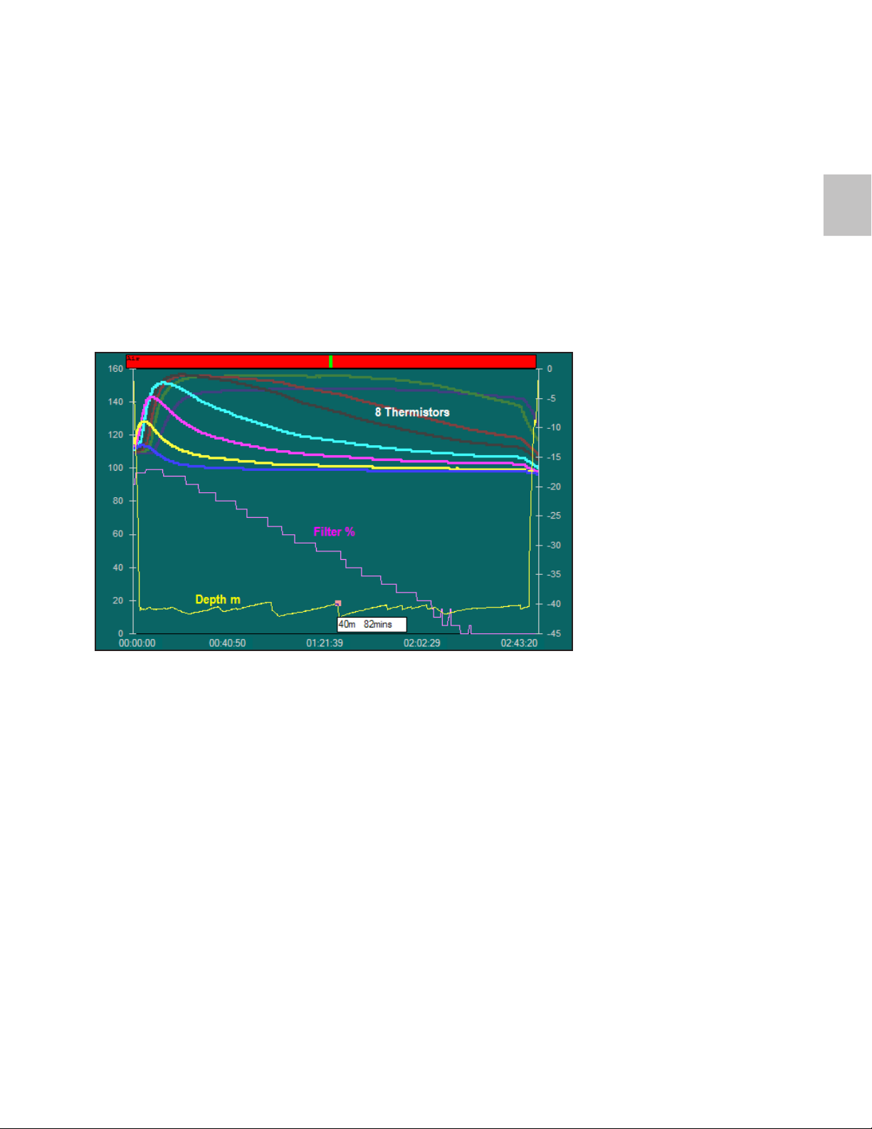
Below is a graph of the data log from a chamber breathing system test
dive. 1.6litres of CO2 are being fed into the system every minute. The
external water temperature is approximately 4 degrees Celsius. It shows
the thermistor readings on an arbitrary scale, canister remaining percent
prediction and depth in meters. The endpoint of the graph is when the CO2
levels reach 5 mBar break through.
3.14
The thermistor curves at the beginning of the dive, as the canister heats
up, have a different shape to the middle to latter part of the dive. It is
not sufficient to simply look for the position of the hottest part of the
canister. This will give poor predictions of canister duration. The algo-
rithm first normalizes temperature difference data. Then uses a tech-
nique to determine which part of the curve the system is on – begin-
ning, middle or end. It then correlates a look-up of the measured data
into the suitable reference data to determine the canister duration.
The filter should always be kept sealed until required for use. Once
installed, the filter should be changed within 24 hours even if it has not
been fully used through breathing. When installed and being unused,
the EXPLORER should have its breathing loop closed so that external
air does not accelerate the degradation of the filter. However, once open
and used, even if only a little, the filter will continue to degrade and
| 45
Page 52

change its characteristics post-dive. Therefore, as previously stated, the
filter should always be changed within 24 hours of opening and/or use.
Partially used filters should be stored in the EXPLORER with a closed
breathing loop.
Although the algorithm that analyzes the thermistor curve is adequately
accurate during diving, if the filter is not being breathed on, the thermistors
curve will be abnormal. It also takes time for the absorbent to rise to normal operating temperatures. Therefore for routine use, the addition of the
Oxygen injection meter (described in the next section) is used to report the
filter percentage remaining to the user.
OXYGEN INJECTION METER
The CO2 created by the diver is in direct proportion to the oxygen
breathed. The oxygen metabolized by the body is replaced by the in-
jection of oxygen into the breathing loop. By knowing the volume of gas
injected, the amount of metabolized oxygen and therefore the amount
of CO2 created can be estimated. From tests, the duration of the filter
types has been determined and the corresponding volume of CO2 ab-
sorbed before the absorbent begins to reduce its effectiveness.
Using these principles, the system measures the amount of gas injected
by the solenoid valve and converts it to a percentage of minutes remaining
at CE CO2 rates. Although the displayed minutes are at CE CO2 generation
standards, the minutes will tick down more slowly if the diver is breathing
at a reduced rate. This will be the most common scenario. However, in the
unusual condition of CO2 generation at an elevated rate compared to 1.6ltr/
min then the minutes will tick off more quickly. If the diver knows a particularly strenuous dive is ahead, they should allow extra conservatism in the
minutes remaining counter, for that dive.
The Oxygen Injection Meter should be used in conjunction with the Temperature profiler and the Gaseous CO2 sensor to determine the appropriate
state of the filter. The remaining Oxygen injection meter percent is displayed on the STATUS screen as a ‘Filter minutes’. The Oxygen Injection
Meter minutes are reset when the absorbent is replaced and confirmed in
the Pre-Dive Sequence.
46 |
Page 53
WARNING: The CO2 Absorbent Filter Alarm will activate when
!
there is sufcient duration to allow an ascent to the surface
with an additional (approximate) 10 minutes reserve remaining.
At such time, the diver should ascend to the surface on closed
circuit.
!
DANGER: If in doubt of the condition of the CO2 lter, replace
the absorbent and perform full pre-dive checks. Filter time re-
maining must exceed the planned dive time.
OPERATION AND INTERACTION OF TEMPERATURE PROFILER
AND OXYGEN INJECTION METER
The thermistor bar chart of the temperature profile through the filter is
shown to give the diver information on the activity of absorbent inside
the filter. This should have a peak when the filter is being breathed on.
From cold it will take about 5 minutes for the CO2 reaction to cause a
visible peak. This peak should then continue and grow higher. The tem-
perature bars fill from the left to the right as the filter is being used. This
screen is in the Pre-dive sequence.
3.14
If there is no peak, then there is a problem with the filter. This could be
caused by:
1. Flooded filter
2. Filter not fitted
3. Filter empty – all used up
| 47
Page 54
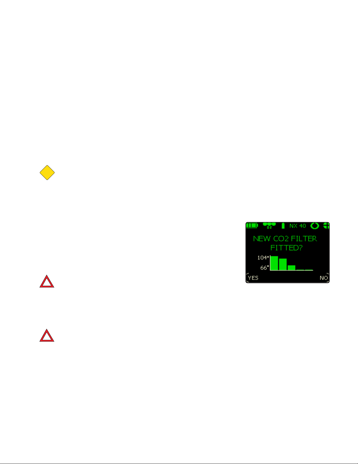
During pre-breathe, the unit needs to be breathed on to see a change in
the thermal profile. This does not guarantee correct operation, but has a
high likelihood of correct operation. Any sense of dizziness, nausea or other CO2 symptoms should also be used to alert the diver that the filter is not
operating correctly. A small bypass due to a badly fitted filter or CO2 seals
could give this scenario of a good peak, but an amount of CO2 could still
bypass the filter. If this occurs, stop breathing on the EXPLORER. This will
be indicated (and alarmed for) by the Gaseous CO2 sensor. Replace the
absorbent and/or check filter packing and seating.
CAUTION
CAUTION: Pre-breathing any rebreather should be done in
a safe seated position where the diver can monitor displays
and any potential symptoms of CO2 poisoning. Pre-breathing
should never be conducted while walking or standing in a place
where the diver could fall into the water or injure him or herself.
The actual minutes remaining number displayed to the diver comes from
the Oxygen Injection Monitor. This gives a consistent and reliable reading
of current absorbent duration based on Oxygen injection.
Always remember to reset the absorbent duration when a new filter is
fitted. You will be prompted to do this during the Pre-dive sequence (Fig
3.21).
DANGER: DO NOT reset the absorbent duration unless a new
!
lter with fresh absorbent has been tted.
Always change the absorbent when the low filter alarm appears, or before
if you suspect the absorbent is not operating correctly or close to the end
of its life - be conservative - be safe.
!
DANGER: If an absorbent lter is not tted, the green central
indicator will not be visible on the Right Hand End Cap and it
will not be possible to breathe off of the loop.
No matter how many safety monitoring systems are in place, use
your own common sense and discipline to ensure you do not
push the life support systems beyond their designed limitations.
It is your life being supported - respect the equipment and its
limitations.
48 |
Fig. 3.21
Page 55
CARBON DIOXIDE SENSING MODULE
Premise:
The EXPLORER comes with an option to fit a CO2 sensor. The user can
elect to buy this from new or upgrade to the sensor later. The CO2 sensor
gives many advantages as detailed below.
EXPLORERS not fitted with CO2 sensors or that have had their CO2 sensor
temporarily removed by the user, can still be dived but with no CO2 sensor
fitted a 5 minute pretreated of the absorbent filter will be forced in stead of
the normal 1 minute.
!
DANGER: With no CO2 sensor tted careful monitoring of lter
duration is vital.
There is little confirmed data on actual absorbent durations typical for sport
diving rebreather use. Sports divers often push the absorbent duration beyond the published CE durations, because they assume that they will not
be creating as much CO2 as the CE trials or operate at the same temperature or depths.
3.14
The problem can arise that if a diver has gone deep and works hard, perhaps to rescue another diver; when the absorbent duration is near its limit,
the extra depth and work rate push the CO2 to dangerously high levels very
quickly.
The CO2 sensor will help by giving feedback in this scenario, and advise
the diver of the high CO2 levels. The diver should then reduce their work
rate and reduce their depth and finish the dive as safely as possible or bailout to open circuit as indicated. The relatively fast rise in CO2 readings is
also an indication that the absorbent cannot be pushed any harder without
causing even higher CO2 levels.
A question asked already by many divers who have seen the system in
operation, is “Can the CO2 reading be used to determine the duration
remaining in the filter?”
The answer in principle is ‘yes’. However with the current knowledge and
data available, there is no practical system to achieve this. The duration of
the absorbent changes with CO2 generation, temperature, depth, and re-
| 49
Page 56

breather design. People have achieved over 8 hours duration with relatively
small absorbent loads, but this has been in warm water, with low breathing
rates and shallow depths. It is currently not known what the effects are
when an absorbent filter working at a CO2 level of say 2mBar that has been
used in a shallow scenario is taken deeper and the work rate is increased.
We know that the CO2 would increase, but do not know how fast. In field
tests, we have seen the CO2 jump quickly from 3mBar to 6mBar just by the
diver going deeper near the end of absorbent duration. This same rise will
not occur if the filter is at the start of its life. Forecasting potential duration
with the CO2 sensor will be possible in the future after more development
but this is not currently the main function of the CO2 sensor. Its’ current
functionality is as an active warning device for CO2 absorbent system
issues. It can detect for bad absorbent, no absorbent, high work rates
and general CO2 seal issues.
WARNING: Currently the CO2 sensor reading should not be
!
used as a duration meter for the rebreather. It is vital that it
is used to report and alarm for a high CO2 reading that could
occur with a faulty seal or exhausted absorbent.
Our bodies produce the same CO2 quantities independently of depth. So
just staying shallow does not reduce CO2. It can however; help the CO2
absorbent perform more efficiently. Therefore a low CO2 reading on a filter
that has been used in shallow water for some time may rapidly increase if
(towards the end of its’ life) it is taken deeper or the work rate increases.
Be aware that the CO2 reading can rise dramatically for higher work rates
and deeper depths, especially when an absorbent has been used for over
50% of its recommended duration.
Therefore, in order of priority, the EXPLORER is fitted with a gaseous CO2
sensor, a metabolism ‘click’ counter (providing an estimate of oxygen consumed, hence CO2 generated) and a TPM giving an indication of thermal
activity within the filter. These three features give a more accurate indication of absorbent life remaining.
The use of the CO2 readings is four fold:
1. To ensure active absorbent has been fitted
2. To ensure the absorbent sealing systems are operative
3. To warn of reducing absorbent efficiency in order to give the diver time
to respond by reducing depth, temperature or work rate to avoid an incident occurring.
50 |
Page 57
4. To warn of rare situations when excessively high CO2 levels may require
immediate bailout to safe open circuit gas.
!
DANGER: The CO2 sensor should NOT be used to determine
absorbent duration.
NOTE: As more actual dive data becomes available it may be
possible to model the CO2 curves and generate some level
of prediction of remaining absorbent life. This is currently a
work in progress.
CO2 – CARBON DIOXIDE SENSOR FOR EXPLORER
This section describes the operation of the CO2 sensor as fitted to the
EXPLORER rebreather.
The EXPLORER CO2 sensor is the world’s first commercially available carbon dioxide sensor proofed and designed by VR Technology for operation
in a high humidity, high oxygen rebreather breathing loops.
3.14
The CO2 sensor actively measures carbon dioxide while the user is breathing on the loop. It can thus warn of high CO2 levels before unconsciousness or other symptoms occur, in time for the user to perform remedial
tasks such as finishing a dive, reducing activity or even bailing out to other
gas sources.
BACKGROUND
It should be noted that this is the first use of a CO2 sensor in an active-user
breathing loop. As such, new data on CO2 levels will be obtained that will
identify areas of adjustment of common practice and improved use of the
CO2 readings as time goes on.
Much of the research in CO2 poisoning has been conducted with military
levels of exertion and requirements. From this research the 5 to 10 mBar
limits for CO2 were formalized as the upper working range for CO2 by a
diver undergoing considerable exertion. Thus the alarm levels within the
EXPLORER have been initially set as 5mB and 10mB. As the user moves
into the 5 mB+ range, although no symptoms may occur, it is highly advisable that the dive be terminated as soon as possible.
| 51
Page 58

It is assumed that CO2 levels in the region of 15 – 20mB are potentially very
dangerous and potentially fatal, and the user could easily lose consciousness with little or no warning and as such it is potentially extremely dangerous to work at any CO2 level above the 10mb range.
MAIN FEATURES
The CO2 sensor consists of a proprietary combination of filters and sensors
that together provide a robust CO2 monitoring system for breathing loops
in rebreathers. The CO2 sensor is able to compensate for pressure and
humidity environments as normally achieved in a diving rebreather system.
The EXPLORER version is powered from the LSS Module rechargeable
battery.
The CO2 sensor requires occasional calibration. EXPLORER has a sophisticated logging system that minimizes the number of calibrations. It also
removes the need to use CO2 calibration gasses.
WHAT SHOULD I EXPECT TO SEE ON THE CO2 SENSOR READINGS?
As a unique CO2 sensor in an active breathing loop, some user education
is required to understand the benefits, features and limitations of the device. From this standpoint, it is worth the user taking a short time to understand more of how CO2 is dealt with in the breathing loop.
CO2 filter endurance is reduced by increased depth, low water temperature
and high work rate (CO2 generation) variables. As the user pushes the CO
absorbent filter towards (or past) the end of its CE tested limits, the levels
of CO2 in the loop may be surprisingly high or could be low if the variables
are less extreme but could accelerate rapidly dependant on the rebreather
design.
Some divers feel they are getting more duration because they are not
producing as much CO2 as that used in CE trials or that other variables are
less extreme within their diving environment.
Information from field use with the CO2 sensor indicates the filter durations are actually quite close to the CE durations and the 5 mB CO2 point.
However, 5 mBar of CO2 is not fundamentally damaging. Metabolism and
52 |
2
Page 59
respiration can occur to some degree even up to 20mB CO2. However, the
amount of exertion and other pressure related effects mean that this is unadvisable, and CO2 poisoning and death may occur at levels in the 10-20
mB range in some cases. So some of the extended durations currently experienced are due to the user taking the CO2 level into the 5-10 mB range,
without any obvious symptoms of CO2 poisoning.
The user must be aware that strenuous exertion when CO2 is at these
elevated levels can quickly cause the CO2 levels to rise rapidly. As the
symptoms of CO2 poisoning are almost impossible for the user to recognize – they will just pass out and may drown. However, the readings from
the CO2 sensor showing that CO2 levels are rising (while still not exhibiting
symptoms) should be used as much as anything to limit the strenuous
activity and further use of the filter after the dive has finished.
!
DANGER: New dives must not be performed on the lter once
CO2 levels in the 5-10 mB region have occurred, regardless of
how short a duration. Some rebreather fatalities are possibly
due to users pushing the CO2 lter with strenuous activity near
the end of the lter life.
3.14
Increased depth or reductions in temperature when the CO2 filter is near
the end of its life are also not advised, as the filter is less able to cope with
high CO2 levels. So increased depth, coupled with muscular activity and
cold are a very bad combination when near the end of filter life where CO2
levels are already raised.
NOTE: Conversely, reducing your depth and work rate and
returning to warmer water, are all good ways to manage CO
2
levels until you can return to the surface and change the
lter. In any event if a CO2 alarm is seen the EXPLORER will
force an immediate action to return you to the surface.
| 53
Page 60
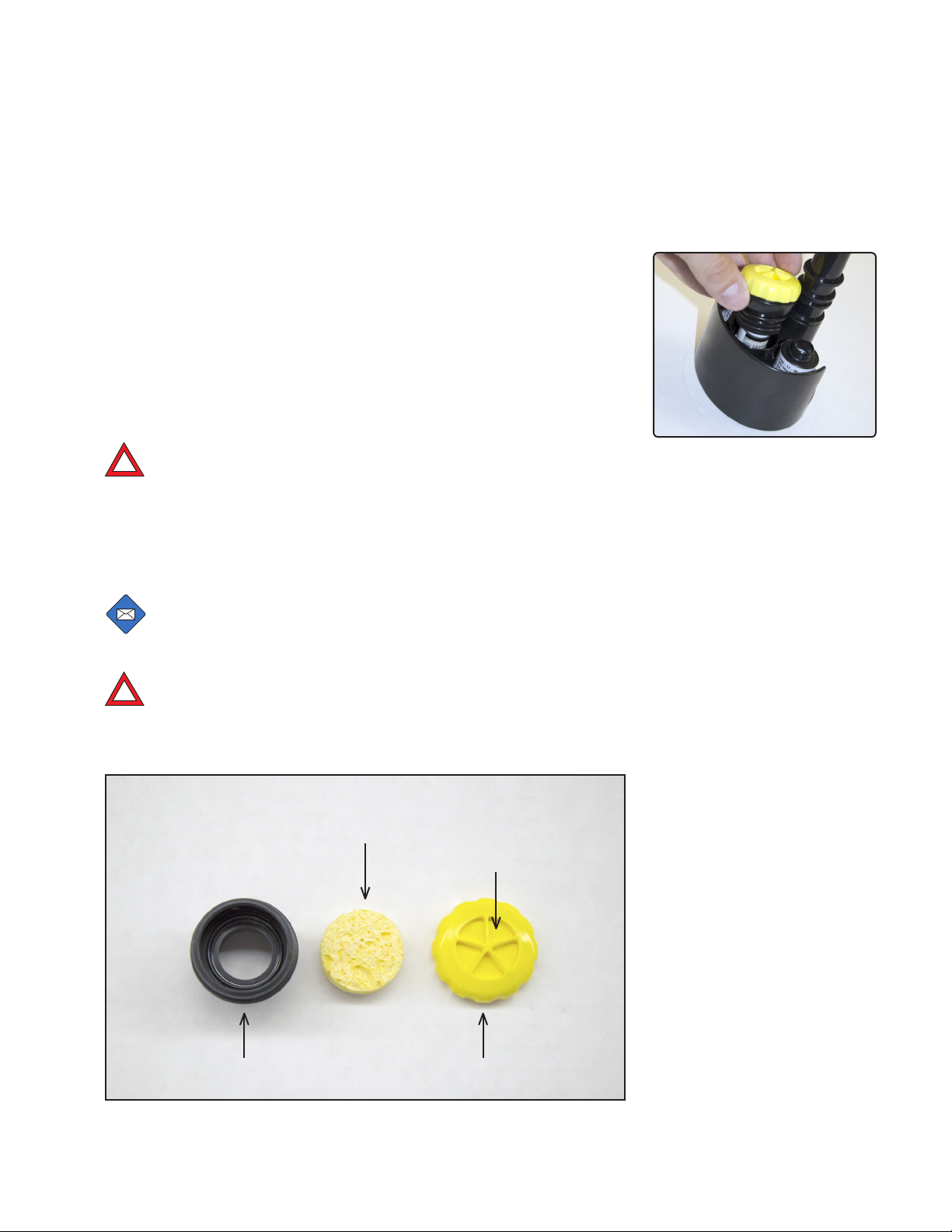
GASEOUS CO2 SENSOR SYSTEM CONSTRUCTION
The CO2 sensor system comprises of a Sensor and a removable/changeable filter. The basic principle of the system is to use Infra Red technology
to detect carbon dioxide (CO2) in the retreaters’ breathing loop. However
certain contaminants and in particular moisture, will affect the sensors ability to read accurately. To help with this issue, the assembly comes complete
with a user-changeable filter system that can be simply disconnected from
the Sensor Module and serviced by the diver (Fig. 3.22).
DANGER: It is vital that to maintain accurate CO2 readings the
!
performance of the ltration system is maintained and a dry
piece of absorbing material tted before every dive. Calibration
of the sensor must be conrmed periodically by exposing it to
air. CO2 readings in air should be 0.4 ± 0.1 mb. If in doubt then
recalibrate the sensor.
NOTE: Readings in air should be between 0.4 ± 0.1mb.
CO2 FILTER CARE
!
DANGER: For accurate CO2 readings, a clean and dry piece of
absorbent material must be tted prior to every dive. Different
environments will produce different amounts of moisture and
hence the lter change-out routine may vary.
Fig. 3.22
Absorbing
Material
Membrane
54 |
Filter Body Filter Cap
Page 61
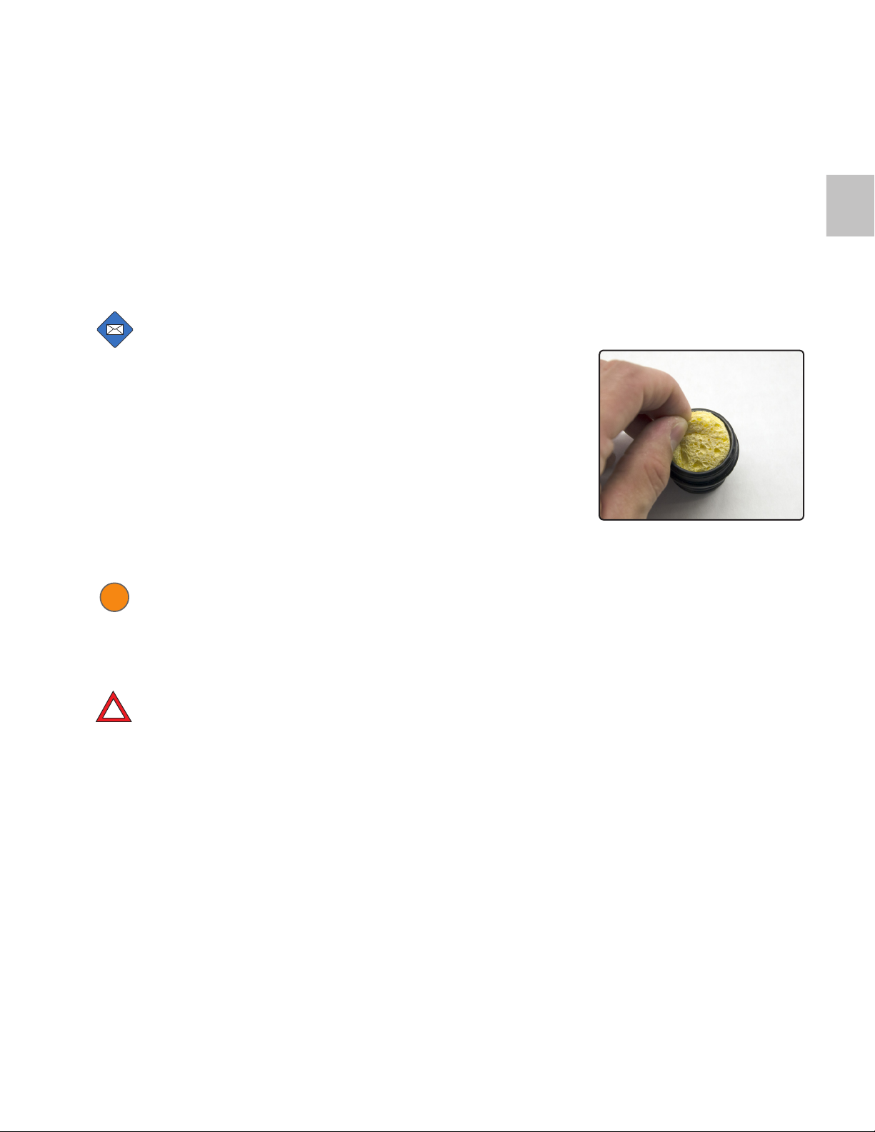
The filter cap attaches to the filter body and is a push fit. The basic construction of the filter starts with a specialist filter membrane in the cap (the
yellow material) backed up by a water absorbing material (the central
sponge like material in the picture).
NOTE: The lter cap retains the membrane (yellow material) that must NEVER be removed. The Sensor itself is not a
user serviceable part and damage may result if it is tampered
with. If the lter cap membrane becomes damaged it must be
replaced.
The yellow water absorbing material (center of picture) is removable. The
EXPLORER is supplied with spare absorbing material. Simply remove one
and refit a new one (Fig 3.23).
3.14
The absorbing material will become wet during a dive. The used absorbing
material can be dried out, preferably in an air-conditioned environment, as
it will become moist during a dive.
WARNING: Each absorbing material piece should only be used
!
for a maximum of 10 dive hours or if damage is noted, replaced
immediately or sooner if the readings from the CO2 sensor are
not within the expected range (i.e. almost 0mb at the end of the
Pre-dive sequence with a new lter tted).
DANGER: Failure to replace the absorbing material may result
!
in faulty CO2 readings.
If debris is noted on the front face of the membrane (yellow material) or if
it is suspected that contamination is restricting the flow through the membrane, it should be replaced.
Fig. 3.23
| 55
Page 62
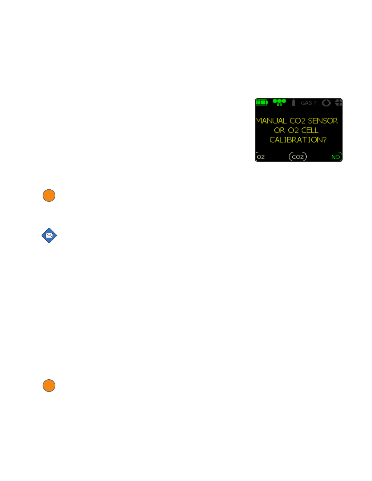
CALIBRATION
During the Pre-dive sequence you are prompted if you want to calibrate
the CO2 sensor (Fig. 3.24).
The ONLY source of calibration gas is fresh air. With the filter removed
and the sensor in fresh air the CO2 reading should read 0.4mb +/-
0.1mb. Leave the sensor exposed for at least 5 minutes. The on-screen
prompts will guide you through the calibration. This involves removing the
exhale hose from the mouthpiece and breathing the unit for one minute to
circulate fresh air into the system.
WARNING: At the end of a Pre-dive sequence with a new lter
!
tted the CO2 readings should be almost 0mb. If this is not the
case then the sensor must be recalibrated (as above) or re-
placed.
NOTE: Post dive, if you want to do another calibration, you
must remove the lter cap to calibrate.
The same system should be used to just check the calibration. There is no
need to constantly calibrate but it is good practice to check the calibration
at the start of a dive sequence using the above method.
Once it is calibrated, to confirm the operation, gently breathe across the
sensor face until the reading changes. Now re-install the filter prior to diving.
Fig. 3.24
After calibration and with the sensor inserted into the loop if a full prebreathe with fresh absorbent is undertaken the CO2 reading should fall to
0mb. This is normal.
Post dive and with no gas flow (breathing) you may see a small rise in CO
levels due to gas density and pocketing. After a pre-breathe this should
stabilize. Blowing into the sensor face may also create the same affect until
it is used again normally in the breathing loop.
WARNING: If at anytime you see a reading that is abnormal you
!
should check the calibration.
56 |
2
Page 63

Abnormal readings could include:
1. A reading fixed at zero or any other number when you are breathing
directly onto the sensor face with the rebreather disassembled.
2. An abnormally high reading during a dive.
NOTE: Under CE conditions after approximately 50 minutes
at 40 m at 1.6 l of CO2 (very high workload) in 4 °C/39.2 °F it
should read 5 mb.
3. Readings that change up and down (not in one direction). This could
be a faulty sensor or a faulty connection into the Sensor Module.
The CO2 sensor will benefit from calibration at the start of a dive sequence
and if the sequence is longer than 1 week, at the start of each new dive
week. When having not been used for over a month or if you suspect a
bad reading (see additional notes on filter care) a calibration must be done
prior to diving. It is good practice for the user to check the approximate
validity of the CO2 readings regularly, ideally prior to any dive. Simple
testing by breathing directly onto the sensor should see the reading rise
within approximately 1 minute. Also exposure to clean fresh outside air
should give a reading in the order of 0.4 mB. The unit will respond faster
with the filter removed. So the user must familiarize themselves with the
operation and assembly of the system to be confident the device is working correctly. Consult your Hollis dealer if in doubt.
3.14
WARNING: If you wish to calibrate the unit you must ensure
!
you are in fresh ventilated (outside) air. DO NOT calibrate in a
closed room. The calibration method is discussed above and is
detailed step by step in the pre-dive sequence.
ELECTRICAL CONNECTION
The connector for the CO2 sensor is imbedded into the Sensor Module
next to the 3 x O2 sensors.
NOTE: If moisture is present when this connection is mated,
then contact corrosion may occur. This may give false readings on the CO2 sensor.
It is vital this connection is kept clean. hollis approved contact cleaner or
| 57
Page 64

white vinegar and a soft brush can be used to achieve this. Inspect this
connection regularly.
MECHANICAL FITTING
The sensor should be fitted into the EXPLORER Sensor Module.
Check the O-rings around the filter carrier are not damaged. Ensure the
O-rings are lightly greased.
Ensure the absorbing material is clean, dry and not damaged. The filter
assembly should be periodically checked for water or mechanical damaged. It is advised to keep spare replacement filters. The filter is the main
protection for the sensor from the breathing loops general environment.
If damage occurs to the filter or it becomes exhausted, then damage will
result to the CO2 sensor itself. So always keep in it good condition.
NOTE: After a days diving, you can remove the Sensor Module from the rebreather and keep the Sensor Module (and the
sensors) in a dry environment (air conditioning if possible)
until the next dive. Removing the CO2 lter assembly to venti-
late the CO2 sensor is also advised.
CALIBRATION SCREEN
To access the CO2 feature for calibration go to the "CO2 option" in the Predive screens.
WARNING: The CO2 sensor MUST always be calibrated in fresh
!
clean air, outside, preferably at sea level.
Select the CO2 option (Fig. 3.25) and EXPLORER will prompt you through
the setup procedure and calibration will occur automatically.
Always check that the sensor reading after calibration reads approximately
0.4± 0.1 mBar.
DIVE SCREENS
In the Main Dive screen (Fig. 3.26) the CO2 reading is found by accessing the STATUS screen by a double press of the right button. Then scroll
58 |
Fig. 3.25
Fig. 3.26
Page 65
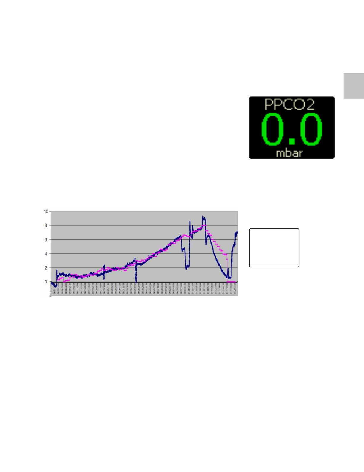
through the screens to see CO2.
Scrolling through the screens to the CO2 display will now display the CO2
reading in Millibars in the central window (Fig. 3.27).
CE TESTING OF CO2 SENSOR
Gaseous CO2 sensor module:
Tests conducted at ANSTI test systems.
As can be seen from the graph below, the CO2 sensor readings keep in
close correlation with the ANSTI Teledyne Lab CO2 analyzer. The Blue trace
is the ANSTI detector. The CO2 sensor is represented in pink. The quick
occasional changes to the Blue ANSTI trace are calibration tests to ensure
accuracy of the measured readings.
3.14
Fig. 3.27
KEY:
BLUE = ANSTI
PINK = CO2 sensor
(inside breathing loop)
Y scale = CO2 mbar
It can be seen from the graph that after 60 minutes there is less correlation
between the in loop and ANSTI readings. This is due to the rapid ascent
rate pressure change causing a temporary temperature drop. The CO2
sensor will quickly recover from the temperature drop.
To a lesser extent, there is also the reverse condition at the beginning of
the dive, where the chamber is being pressurized and the temperature is
rising. Within a few minutes the readings are correlated.
| 59
Page 66

Display & Alarm Systems
HUD, BUD, & COLOR SCREENS
The EXPLORER can be routinely dived by using the HUD (Heads Up
Display) as the main underwater human interface. This frees up the
diver to concentrate on the dive at hand.
The HUD is in the divers vision and attached to the BOV. It utilizes color
LED's and a vibration feature to get your attention when necessary.
Additionally, the EXPLORER has a BUD (Buddy Universal Display) on
the side of the LSS Module for the Buddy/Instructor to see your status
at a glance. Both the HUD and BUD indicate the same color codes.
If the HUD/BUD system changes from Green for ‘go mode’ to a flashing
green/blue then the diver can refer to the main wrist display and
investigate the additional information on the STATUS display.
The wrist display utilizes color as an alert for general status changes
and couples this alert with unprecedented clarity of information that can
be reviewed in further detail.
The HUD, BUD, color screens on the wrist display, and uncluttered
screen layouts are key to providing the diver and dive team with
essential information in high stress scenarios.
60 |
Page 67

DEFINITIONS
Alarm (state): These are mostly alarm(ing) conditions, but not always. They
could represent a state of the system that is displayed in some way other
than via the HUD or STATUS screens.
Alarm Display: The method by which an alarm state is passed to the user.
On the LSS module, the HUD, BUD, and tactile alarm are used. On the
handset, this is done via the GUI (Graphical User Interface) displays and
the STATUS screen, which also has an ACTION Panel reflecting the HUD
and a message containing a single user action. Some alarm displays vary
depending on other system states, such as other alarms or the dive status
(e.g., diving, not diving).
ALARM CODES
With the EXPLORER, a key task has been to process the fault levels and
error conditions to indicate the status of the rebreather. Further, the LED
states are configured for color blind as well as highly stressed divers.
The position of the LED’s coupled with the flashing or solid states,
provide conditions that cannot be confused with one another. During
stressful dive scenarios, the position and status is quickly understood
to speed up the desired response/correction by the diver. The status
sceens on the wrist display add one more level of security by adding
extra information on an alarm states.
3.15
WARNING: This information is in English, and all users should
!
be adequately trained in interpreting this information appropri-
ately.
| 61
Page 68

There are 3 main warning levels associated with the HUD, BUD, and
on-screen displays.
Alarm Code Meaning Correct Action
Solid Green This code means there
are no detected prob-
OK - Procede with dive
as planned.
lems.
Flashing Green & Blue
(HUD/BUD)
&
Yellow
(wrist display)
Warning - It is activat-
ed when a manage-
able error situation is
in place.
The correct response
will be displayed on
the STATUS screen
and will often tell the
diver to ascend slowly
on closed circuit
monitoring the wrist
display.
Magenta (wrist display
only)
Loss of communication between sensors
or modules. It is
usually associated with
Check the status and
for any message on
the wrist display an
react accordingly.
DO NOT dive or OC
bailout but could just
be a warning.
Flashing Red
& Vibrating
It is activated when
there is an urgent
issue.
- DO NOT start the
dive.
- If already diving, the
diver should switch
to the bailout gas and
ascend.
NOTE: Red alarms take priority in the HUD over Green/Blue
alarms.
NOTE: Yellow on the display is equivalent to the alternating
blue/green state of the HUD.
NOTE: The HUD vibration alarm will vibrate every second for
5 seconds, then repeat the 5 second alarm every 30 seconds,
or if the source of the alarm changes.
62 |
Page 69

Alarm flow diagrams
The following sections contain flow diagrams to indicate which actions /
HUD indication will be used separated into diving and surface cases.
The following flow charts should be used in sequence, where an OK from
the red HUD cases leads to blue/green HUD cases. Note the following
decompression/tissue model ‘O/C Bail-Out’ alarm states (used in the diagram):
No Comms — Pressure Sensor alarm is “No Comms”
Stale — Pressure Sensor alarm is “Stale”
Missed Stop — Deco Ceiling violated for more than 1min. This alarm
state latches for 24 hours.
Too Shallow — Deco Ceiling violated for < 1min
At Stop — Within 0.1 bar (deep) of the next stop
Near Stop — Within 0.3 bar (deep) of the next stop
Too Deep — Greater than 0.3 bar (deep) of the next stop
3.16
| 63
Page 70
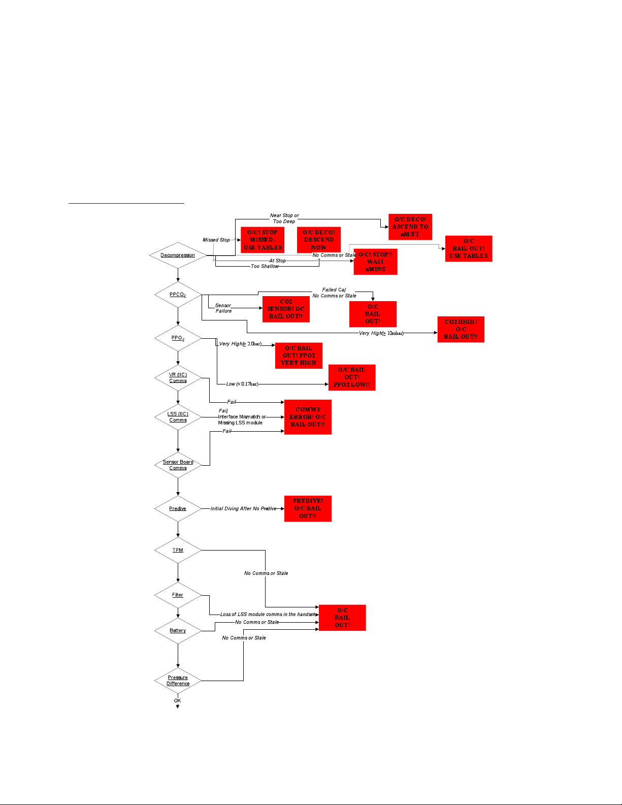
IN WATER HUD/BUD ALARMS
Red (OC Bailout) Alarms
64 |
Page 71
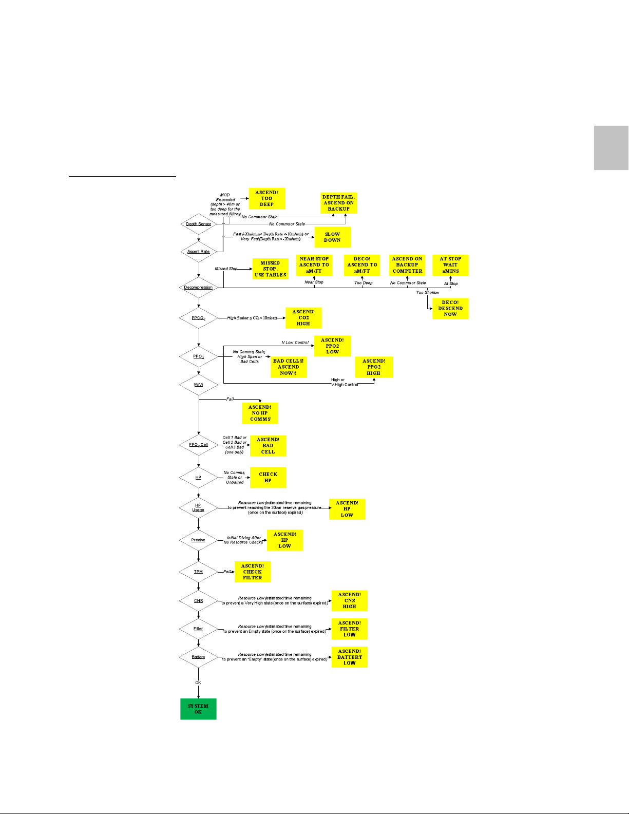
Blue/Green Alarms
3.16
| 65
Page 72

PPO2 "Bad Cell" States Are As Follows:
• Cell input timed-out
• Cell input stale
• Calibrated sensor input > 3.00 bar
• Calibrated sensor input < 0.15 bar
• Raw sensor input < 7 mV
• Cell input excluded having failed calibration
• Calibrated cell input > 0.2 bar from the other two cells (only a single cell
can be in this state)
PPO2 "Ascend" Alarm States Are:
High Span
PPO2 cell span > 0.5 bar (if 2 or 3 cells in state “OK”)
Bad Cells
1 cell in state “OK” or; no cells in state “OK” but with different high/low
alarm states or the same alarm states and no O/C bailout case
V. Low Control
If 2 or 3 cells in state “OK”, and PPO2 < -0.20 bar
V. High Control
If 2 or 3 cells in state “OK”, and PPO2 ≥ 0.70bar where; PPO2 = PPO2 –
setpoint, i.e., the difference between the average PPO2 and the setpoint.
The average PPO2 is based on the calibrated value from all cells in alarm
state “OK”.
66 |
Page 73
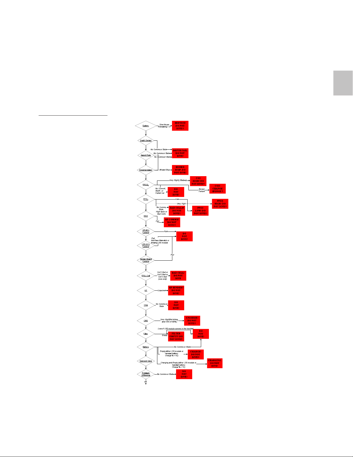
SURFACE HUD/BUD ALARMS
Red (Do Not Dive) Alarms
3.16
| 67
Page 74

PPO2 "Bad Cell" States:
• Cell input timed-out
• Cell input stale
• Calibrated sensor input > 3.00 bar
• Calibrated sensor input < 0.15 bar
• Raw sensor input < 7 mV
• Cell input excluded having failed calibration
• Calibrated cell input > 0.2 bar from the other two cells (only a single cell
can be in this state)
PPO2 "Do Not Dive" alarm states are:
No Comms
All PPO2 cell alarms are “No Comms”
Stale
Any PPO2 cell alarm is “Stale”
High Span
PPO2 cell span > 0.5 bar (if 0*, 2 or 3 cells in state “OK”)
Bad Cells
None or 1 cell in state “OK”
Very High
If 0*, 2 or 3 cells in state “OK” and average PPO2 ≥ 2.0 bar
Low
If 0*, 2 or 3 cells in state “OK” and average PPO2 < 0.17 bar
where; PPO2 = PPO2 – setpoint, i.e., the difference between the average
PPO2 and the setpoint. The average PPO2 is based on the calibrated value
from all cells in alarm state “OK”.
* Zero cells “OK” with the same high/low alarm state, in which case all three are used in the
average.
68 |
Page 75
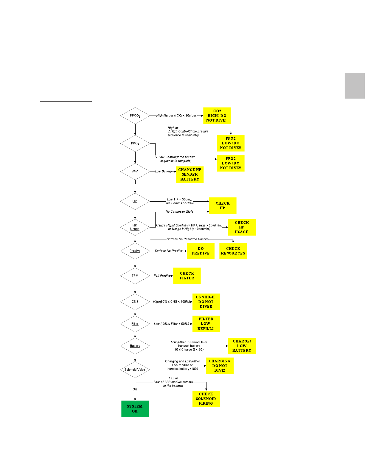
Blue/Green Alarms
3.16
| 69
Page 76

PPO2 Blue/Green ‘Do Not Dive’ alarm states are:
High
If 2 or 3 cells in state “OK” and average PPO2 ≥ 1.6 bar
V. High Control
If 2 or 3 cells in state “OK”, and provide complete, and PPO2 ≥ 0.70 bar
V. Low Control
If 2 or 3 cells in state “OK”, and predive complete, and PPO2 < -0.20 bar
where; PPO2 = PPO2 – setpoint, i.e., the difference between the average
PPO2 and the setpoint. The average PPO2 is based on the calibrated value
from all cells in alarm state “OK”.
70 |
Page 77

PRIMARY ELECTRONIC BAILOUT SCENARIO CHART*
3.16
Failure
Loop HUD
mode
None Usable
loop
Bad sensor Usable
loop
Bad sensor
readings
Usable
loop
(error greater
than 0.5
PPO2).
PPO2 exceeds safe
Usable
loop
limits or multiple sensor
errors
Wireless HP
data loss
High CO2
(>5 mb)
Very High
CO2 (>10
mb)
Usable
loop
Usable
loop
Unus-
able
loop
status
Solenoid
fire
Primary display Action Deco
Green Y System OK None. Stay on
EXPLORER
Blue/
Green
Blue/
Green
Y – Failsafe mode
Y – Failsafe mode
STATUS screen action
panel will show ASCEND NOW.
STATUS screen action
panel will show ASCEND NOW. PO2 panel
Stay on EXPLORER and
ascend
Stay on EXPLORER and
ascend
will be in Magenta (No
Comms)
Red Y depen-
dant on
DCP/PO
Blue/
Y STATUS screen action
Green
BAILOUT Ascend on
open circuit
2
Stay on EXpanel will show ASCEND NOW. HP panel
PLORER and
ascend
will be in Magenta (No
Comms)
Blue/
Green
Red Y depen-
Y STATUS screen action
panel will show ASCEND NOW.
BAILOUT Ascend on
dant on
DCP/PO
2
Stay on EX-
PLORER and
ascend
open circuit
will follow
On-board, 3
sensor driven
PO
2
Air
Air
Air
On-board, 3
sensor driven
PO
2
On-board, 3
sensor driven
PO
2
Air
* (see Alarm Tables for lower priority alarms)
| 71
Page 78

3.17
Gas Reserves
DYNAMIC RESERVE
The EXPLORER monitors the high pressure (HP) contents of the on-board
gas supplies.
The EXPLORER includes two warning system for the HP contents.
1. Pressure below reserve level
2. Rate of use of gas is too high or too low indicating either a leak or that
the HP cylinder valve is turned off and gas injection is being unsuccessfully
attempted.
The gas supply reserve level is dynamically adjusted based on depth
(because ascent times vary with depth) and assumes a stressed breathing
rate of 20 l/min on open circuit bailout using the on-board cylinder. If the
system sees this reserve limit approaching, it will warn the diver to ascend.
BAILOUT TO OPEN CIRCUIT
Should the operation of the EXPLORER generate an emergency alarm (red
HUD LED and vibrating HUD) then the diver must bailout to open circuit
on either the in-board supply (above 18 m/60 ft) or the off-board supply
(below 18 m/60 ft).
NOTE: Decompression calculations for the ascent profile will
assume air as a breathing gas to provide additional safety
during a bailout ascent.
72 |
Page 79

MOD (Maximum Operating Depth)
The EXPLORER will warn on the main display if the maximum operating
depth of the unit is exceeded. This MOD is based on three things:
1. A maximum depth of 40 m/130 ft
2. A maximum depth such that the gas attached to the unit (as measured)
cannot result in a PPO2 exceeding 1.6bar.
3. When a maximum PPO2 of 1.6 bar is reached
The EXPLORER will not freeze the user out of operation if these depths
are exceeded. However, the system and diver are operating beyond the
normal recommended conditions and therefore these limits should never
be routinely exceeded.
WARNING: Exceeding these limits is not condoned by the man-
!
ufacturer and is not a safe diving practice and must be avoided.
If an MOD alarm is seen then you should ascend immediately to
a depth where the alarm is not displayed. This depth reduction
should be at least 6 m/20 ft but could be more if the MOD has
been exceeded by a large amount.
3.18
| 73
Page 80
3.19
Decompression contingency
The EXPLORER is designed for recreational diving without decompression.
All dives however require safety decompression stops to be conducted
(consult your training agency for information).
If you accidentally stray into decompression the system will generate a
green/blue HUD alarm, the decompression stop, and stop time will be
displayed on the STATUS screen. This feature is designed for contingency
purposes only.
!
DANGER: The EXPLORER is not designed for use with gases
other than Nitrox.
WARNING: Decompression diving signicantly increases the
!
risk of decompression illness.
Various alarms will be generated if elements of decompression are violated. Please see the Deco States Table below and the EXPLORER flow
charts for further detail.
DECO STATES
State Reason HUD Color
Code
Missed Stop Missed deco stop Blue/Green MISSED STOP!
Too Shallow Deco Ceiling violated
for < 1 min
At Stop Within 1 m/3.3 ft below
the next stop
Near Stop Within 3 m/10 ft
of the next stop
Too Deep >3 m/10 ft below ceiling Blue/Green DECO!
NOTE: When you have decompression stops to complete (or if
any alarm is showing) the STATUS display will remain on (and
not automatically time out).
Blue/Green DECO!
Blue/Green AT STOP
Blue/Green NEAR STOP
Status Screen
Display
USE TABLES
DESCEND NOW
WAIT
x MINS
ASCEND TO
x M (FT)
ASCEND TO
x M (FT)
74 |
Page 81
Internet Reprogramming
The EXPLORER can be automatically reprogrammed and upgraded with
new software downloads from the Internet. The PC Link option enables use
of this feature. Contact the manufacturer web site or your dealer for more
information.
Some updates will be available for a fee. Other updates will be free.
To check if you’re EXPLORER has any available updates and to obtain the
reprogramming software then please go to http://hollis.com/support.asp.
DANGER: After new software is installed you MUST recalibrate
!
the oxygen and CO2 sensors.
3.20
| 75
Page 82

Getting Ready To Dive
gear prep
WEIGHTING
As the counterlungs inflate, the diver may experience movement in the
EXPLORER. This is minimized by tightening the harness or adding trim
weights to the pocket available on the top of the case. A weight of up to
2-3 kg/4.4-6.6lbs can be used.
If the EXPLORER is allowed to move on the divers back, a change in
breathing resistance may be noted. With the Explorer’s back mounted
counterlungs it is important that the Explorer is as close to the diver’s back
as possible.
Your instructor will teach you how to weight yourself correctly.
WARNING: Over-weighting is dangerous. With an empty BCD,
!
no additional bailout cylinder and 50 bar/735 PSI in the main
cylinder you should be able to begin slowly to submerge in a
controlled fashion by exhaling slightly (too much and the ADV
will add gas).
WARNING: It is important to perform weight checks in conned
!
shallow water with at least 50 bar/735 psi bailout gas prior to
any open water diving.
HARNESS/BCD POSITIONING
When adjusting the harness try and imagine that the center of the counter-lungs should be within ± 100 mm/4 inches of the tip of your sternum
to give an optimum breathing performance. While the BCD/harness must
be comfortable it should not be loose. The harness will sit differently on
land compared to when you are in the water.
76 |
Page 83
OCTOPUS, BAILOUT, & CYLINDER CONFIGURATIONS
While the exact gas requirements for any type of diving are a matter of personal choice and predicted by specific level of EXPLORER certification and
training agency, it is vital that a breathable open circuit bailout is carried
at all times for all depths of the dive, of sufficient volume to allow a safe
ascent to the surface with a stressed breathing rate.
NOTE: Certain training agencies may required additional gas
supplies for diving in ‘mixed teams’ (open circuit/closed circuit). Please check with your agency for details.
!
DANGER: It is vital that a breathable open circuit bailout is car-
ried at all times for all depths of the dive, of sufcient volume
to allow for a safe ascent to the surface at a stressed breathing
rate.
!
DANGER: For deep/long duration dives the on-board gas supply should only be treated as a short-term gas supply, used for
a limited period until the off-board bailout gas can be accessed.
WARNING: In depths shallower than 18 m/60 ft you must be
!
able to provide gas to another diver (buddy). This will require
the use of an additional second stage octo attached to your EX-
PLORER rst stage if you are not carrying an external bailout
cylinder.
4.1
NOTE: The BOV is connected to the on-board gas supply.
Dives shallower than 18 m/60 ft dives can be conducted using
only this available gas as a bailout providing that the gas endurance alarms are not exceeded on the unit.
NOTE: Certain training agencies may required additional gas
supplies for diving in ‘mixed teams’ (open circuit/closed circuit). Please check with your agency for details.
| 77
Page 84

The following is offered as a guide when configuring the EXPLORER for
a range of diving conditions. This must be used in conjunction with the
recommendations from your Hollis approved training agency.
Depth On-board Gas Off-board Gas
Less than 18m/60ft 5l @ 200 bar/2940 psi
Not required
(1000 l/40 cuft). Nitrox
32 to 40%
>19m/63ft to
40m/130ft
5l @ 200 bar/2940 psi
(1000 l/40 cuft). Nitrox
32 to 40%
Air to 40% nitrox of
sufficient volume for an
ascent from depth with
a 150 l/5.3 cuft reserve
at the surface after an
open circuit ascent.
Bailout gas volumes should be calculated based on the depth of the dive
and the ascent gas requirements. Cylinders can be positioned on D-ring
attachment points on the harness or optional EXPLORER BCD.
Your Instructor and Training Agency will detail how to calculate for sufficient bailout gas volumes.
COUNTERLUNG VOLUME
The volume of gas in the counterlungs will affect the ‘breathing feel’ of
the unit. Too little gas will make inhaling difficult and too much will make
exhaling difficult. All retreaters have optimal positions in the water where
they have a better or worse breathing feel due the hydrostatic effects of the
counterlung position and the breathable volume within the counter-lungs.
It is important to balance the volume in the breathing loop so that excessive inhale or exhale pressure is not experienced.
Under certain situations the EXPLORER will vent during the exhaled breath.
This will result in a drop in oxygen levels and more gas addition by the
system.
It is possible to balance the loop to an extent by venting a small amount
through your nose, particularly on ascents if the need arises.
78 |
Page 85
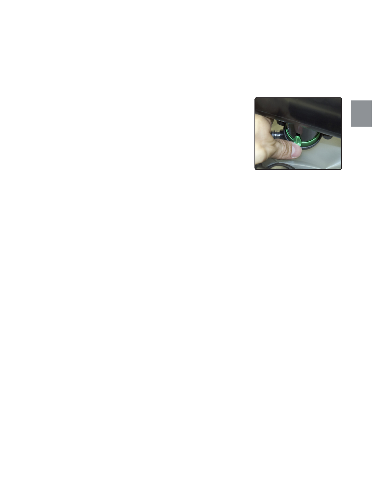
ADJUSTING THE BREATHING ‘FEEL’
The breathing ‘feel’ of EXPLORER is partially controlled by the LCV. Having
removed the case cover this can be seen underneath the Canister. This
is an adjustable valve (over a small range). Oriented as shown, Moving
the valve to the left vents more easily and to the right it vents at a slightly
elevated pressure (Fig. 4.1).
The LCV is a hydrostatically balanced valve, this means that in any swim
position it releases gas from counterlungs at approximately the same pressure and rate. In addition it is a water drain device and it is connected to
the exhale counterlung via a water drain tube such that as water enters the
counterlung (condensed exhaled breath) then it moves through the tube
and out of the LCV regularly throughout the dive.
THE AUTOMATIC DILUENT VALVE
The EXPLORER also has an automatic diluent addition valve (ADV), which
compensates for loss of gas volume. To activate the ADV either descend
or exhale through your nose and breathe in. The ADV is designed to help
maintain a breathable lung volume in conjunction with the LCV.
The ADV on the Explorer is a simple tilt lever system that in the relaxed
position (no gas applied) will remain open. It seals when gas is applied.
4.1
Fig. 4.1
If moisture is present in the system and extreme freezing temperatures are
experienced that are able to form ice within the rebreather this valve could
freeze in the open position. Freezing of ADV’s is a common failure mode
in most rebreathers. The EXPLORER design assumes this and provides an
additional link to the Pre-dive alarm sequence to warn of such a failure.
If the valve is frozen open then gas will freely flow into the circuit. This will
give a ‘HIGH HP’ usage alarm and the unit will fail its Pre-dive sequence.
This is the correct failure mode for this device.
If the system had been pressurized and then it froze and hence the valve
failed closed, again pre-dive will fail momentarily until counterlung collapse
removes the icing as the lever activates, then pre-dive will pass unless
there is a leak due to icing then the pre-dive will again fail (high gas flow
alarm).
| 79
Page 86

This system was developed because in use no units are completely free
from moisture, and ADV free flows, due to icing, regularly occur though
there has not been an alarm for it.
80 |
Page 87
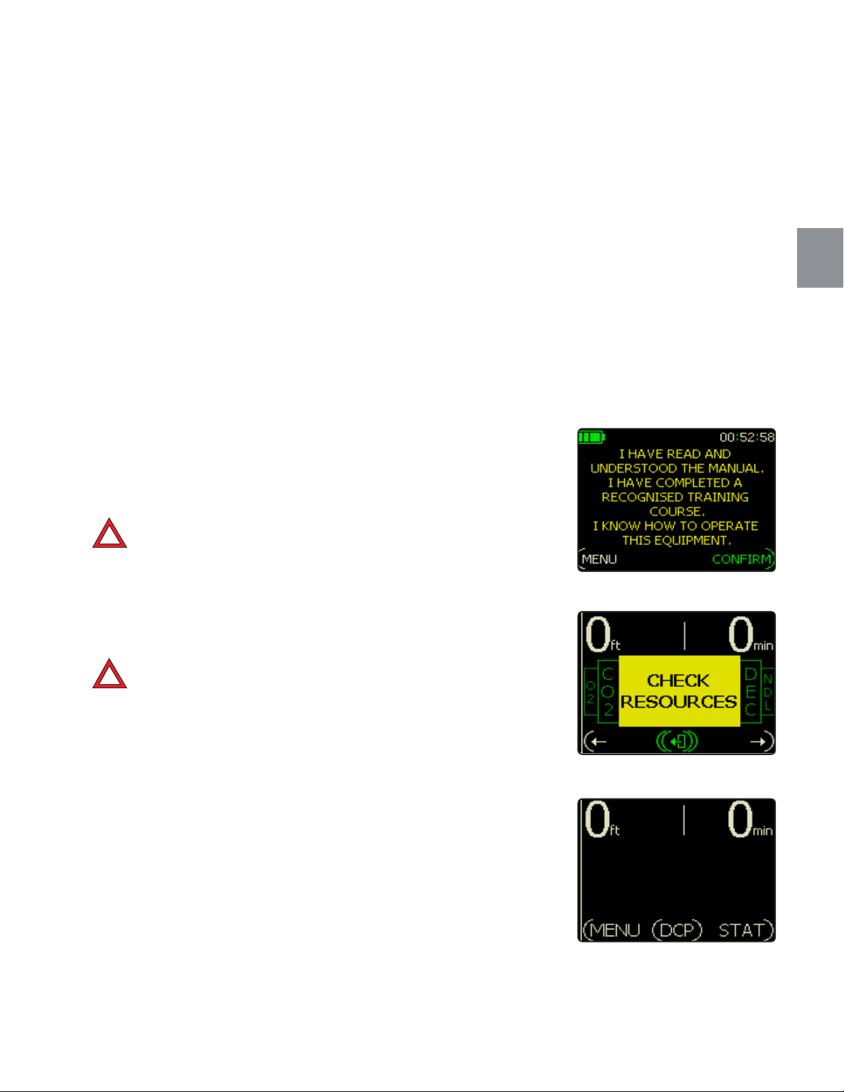
PRE-DIVE SETUP
Having assembled and tested the unit upon receipt, it is still critical that all
pre-dive tests are conducted prior to diving.
The EXPLORER is equipped with a set of pre-dive checks that are built into
the electronics prompting the diver to test certain aspects of the unit prior
to diving. Additionally, there are several manual tasks that should be completed prior to this final system check. These checks automatically start
once you turn the unit on. A complete flow chart of all the screen layouts
can be found on the enclosed CD and in the rear of this manual.
TURN ON SYSTEMS
The EXPLORER can be fully activated in three separate ways:
1. By button push
2. By breathing (breath detection as a low PPO2 of 0.17 is reached)
3. At depth (>1.15 bar absolute pressure or about 5 ft/1.5 m)
DANGER: The batteries must be charged for the automatic sys-
!
tems to work. If the batteries are not charged the unit will not
turn on and not support life.
To turn on EXPLORER simply press both buttons on the handset and
hold for 3 seconds. After which, the Hollis splash screen and then the
training acknowledgement screen (Fig. 4.2) will appear.
4.2
Fig. 4.2
!
DANGER: It important that you have read this manual and are
properly trained in order to complete the Pre-dive sequence
and dive EXPLORER safely. If you have not undertaken these
steps yet, do not proceed any farther.
By selecting CONFIRM the Pre-dive sequence starts and you will be
prompted through the sequence.
At the end of a successful Pre-dive sequence you will see the check
resources screen (Fig. 4.3).
At this point you should cycle through the screens by pressing the
left or right button to check that all resourcesare adequate to complete the dive. After a few seconds the display will time-out to the Dive
screen (Fig. 4.4).
Fig. 4.3
Fig. 4.4
| 81
Page 88
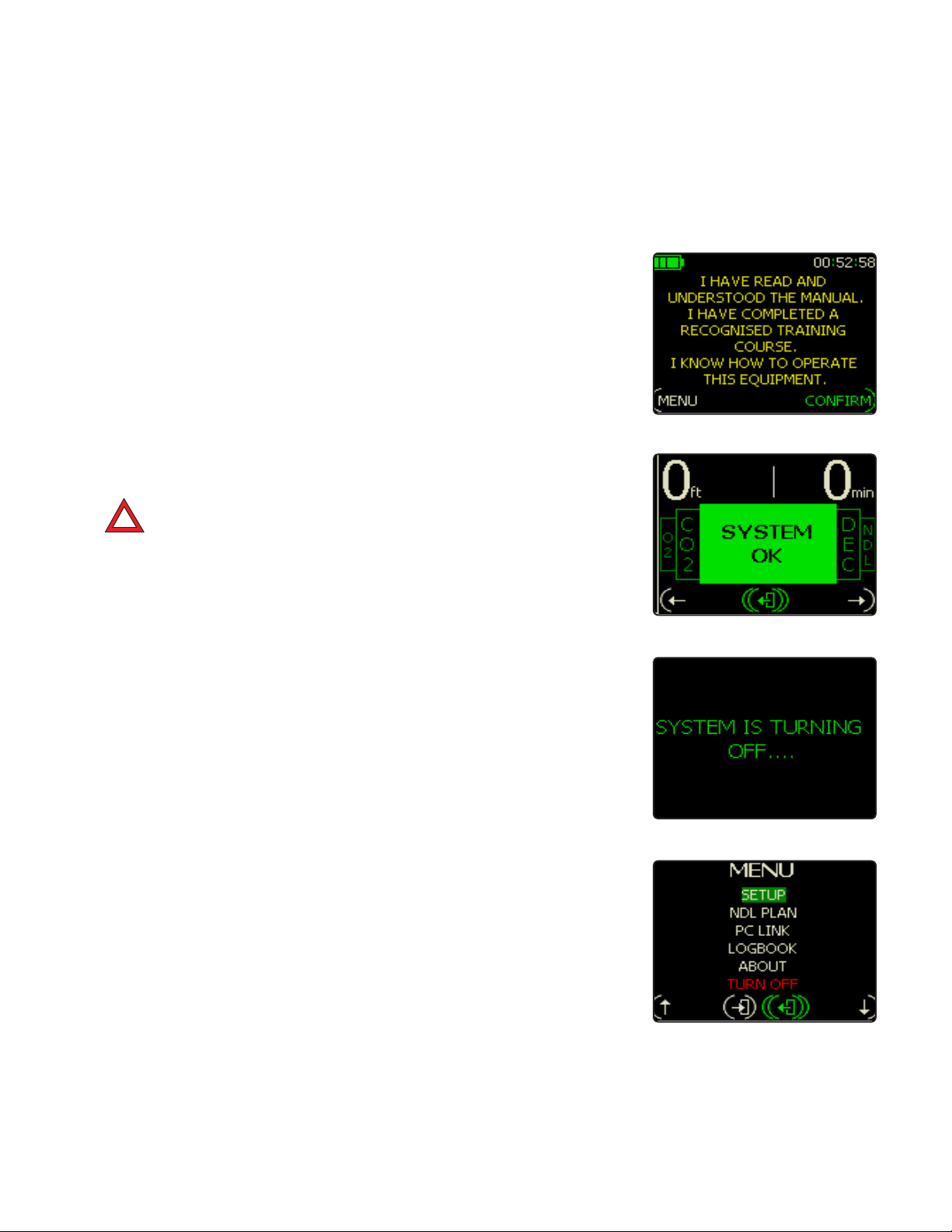
EMERGENCY START-UP SYSTEM (ESS)
Should you have no option other than to enter the water immediately,
EXPLORER will activate the display and show all pertinent alarms in the
STATUS screen. It is vital that you correct anything in error immediately
before continuing to dive.
If you enter the water without completing the relevant Pre-dive checks
and ESS mode is activated, you will be given an O/C bailout alarm (red
HUD) warning you to return to the surface immediately to complete the
Pre-dive checks. After 1 minute underwater (if nothing else is alarming)
the bailout alarm will stop.
!
DANGER: The ESS should never be used as a routine diving
start-up system. A full Pre-dive check MUST always be conducted to ensure safe operation. The ESS is designed ONLY as
a safe guard. If you have not completed pre-dive checks, abort
the dive and perform a proper pre-dive on the surface.
Fig. 4.5
LESS THAN 2 HOUR PRE-DIVE SEQUENCE
If you have completed a Pre-dive Sequence within the last 2 hours, then
upon reactivating the unit (assuming there is nothing wrong with the system) it will display the Hollis splash screen followed by two screens (Fig.
4.5, 4.6). It will then allow you to dive immediately.
TURNING OFF
The EXPLORER cannot inadvertently turn off while submerged. Although
while at the surface, if no button pushes are detected within 15 minutes it
will automatically turn off to save power (Fig. 4.7).
To manually turn off EXPLORER then select the Menu option and do a
long press of the left button - OFF (Fig. 4.8).
Fig. 4.6
Fig. 4.7
Fig. 4.8
82 |
Page 89
FILLING THE GAS SUPPLY CYLINDERS
The nitrox cylinder has a maximum fill pressure. This is stamped on the
cylinder and must be checked before filling. Refer to regional limitations for
maximum fill pressures. Install the nitrox cylinder into the case and tighten
the cam band. Now install the regulator DIN connection.
DANGER: Although the EXPLORER will analyze its own gas
!
supply it is still important that you always analyze your gas
prior to use.
WARNING: If you suspect that the cylinders have become con-
!
taminated with salt, water or other contaminants then you must
get the cylinder inspected and cleaned as appropriate.
GAS ENDURANCE
Gas endurance is defined by the Dive Control Parameter (DCP) setting.
With the cylinder pressurized to 200 bar/2940psi and assuming a usable
gas pressure of the working pressure (minus the regulator interstate pressure of 11 bar/161psi) this equates to 189 bar/2779psi available.
4.2
Assuming a DCP setting of 50% and a worst case FO2 of 32%. The EXPLORER gas supply will last a maximum of 189 minutes based on normal
swimming work rates.
The EXPLORER will continuously update gas minutes remaining throughout the dive for any DCP setting and work rate.
DANGER: High pressure gas cylinders (especially nitrox cylin-
!
ders) must have their cylinder valves opened slowly to avoid
risk of injury.
This duration is also dependent on how much loop venting, mask clearing,
BCD/drysuit inflation occurs.
NOTE: Cylinder valves for use with the EXPLORER must be
certied in accordance with EN12021 for use in Europe.
| 83
Page 90

THE ABSORBENT FILTER
The unit has been tested under CE requirements for CO2 absorbent filter
duration. The weight of absorbent in the filter is approximately 1.5kg/3.3lbs.
Tests were conducted with Molecular Products 797 Grade CO2 Absorbent.
WARNING: Using any other absorbent will change and possibly
!
reduce the Canister duration and could lead to injury or even
death.
CANISTER DURATION
At 40m/130ft of depth, with Nitrox 32% as a diluent at 4 °C/39 °F water temperature with a CO2 injection rate of 1.6 l/min and a ventilation (breathing
rate) of 40 l/min and a 1.5 kg/3.3 lbs absorbent load of a Hollis Approved
absorbent (See Unit Specification), the unit will last 40 minutes at 40 m/130
ft as an extreme test (Ref EN14143: 2003).
This duration changes significantly with higher temperatures and lower work rates
continued
84 |
Page 91
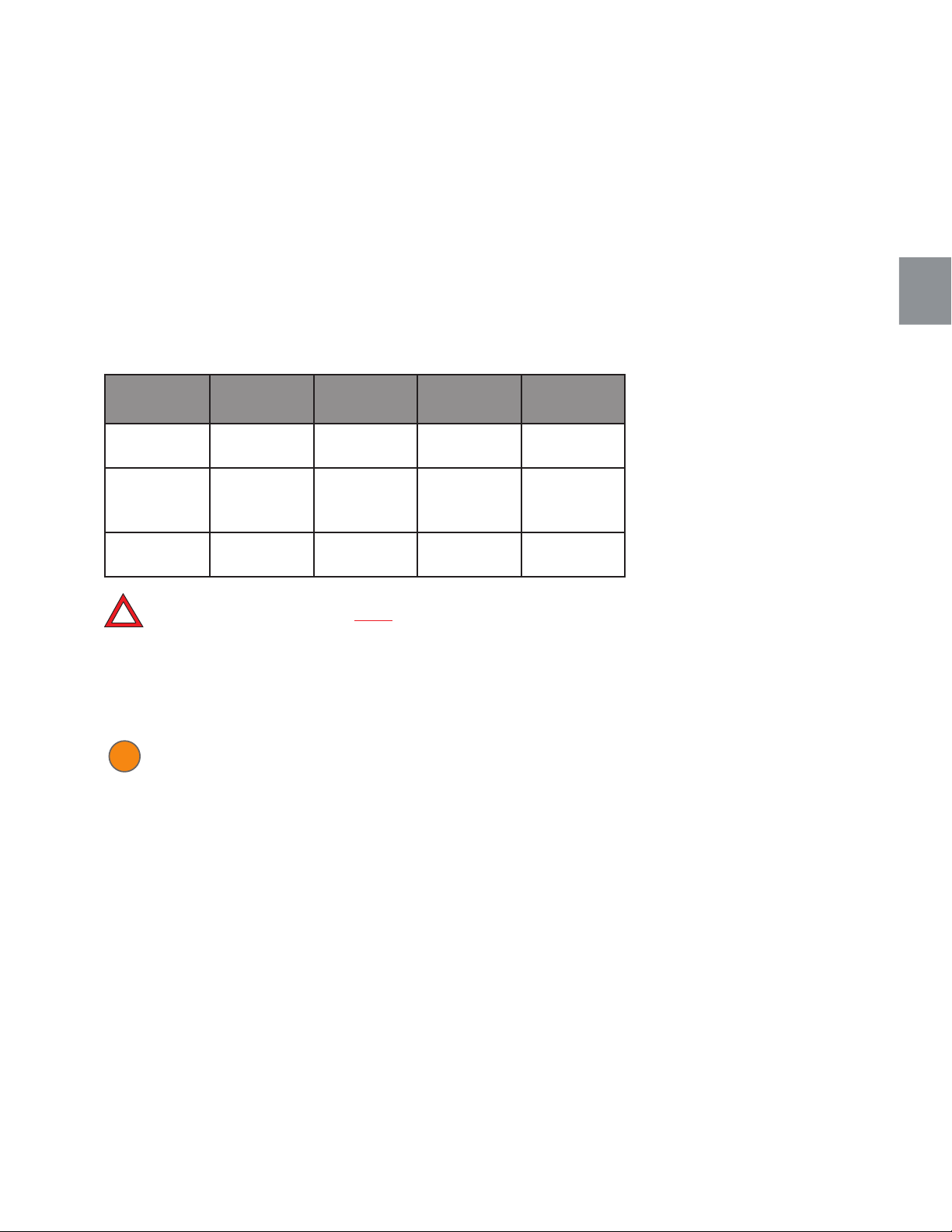
Below is a table of endurance versus depth and changing workloads with
temperature.
MINUTES TO 5MB CO2 REFERENCE
4.2
Depth Total dive
time
40 m/130 ft 37 mins 40 l/min Hard swim-
40 m/130 ft 120 minutes
+reserve
capacity
40 m/130 ft 88 mins 40 l/min Hard swim-
DANGER: Ventilation rates up to 40 l/min are referenced as
!
"Normal swimming" and rates of 40 l/min and above are refer-
enced as ‘Hard swimming’. Under strenuous conditions however consumption rates may be signicantly higher. Regardless
of conditions or readings on the computer, the scrubber should
NEVER be used for more than 2 hours.
WARNING: These tests were conducted using Hollis approved
!
absorbent grade and durations can only be duplicated using
this grade. DO NOT use any other type of absorbent with the
EXPLORER. Safety data on absorbent products can be found
at: http://www.molecularproducts.co.uk
Ventilation
Work rate Water temp
rate
ming
22.5 l/min Normal
swimming
ming
4° C/39° F
15° C/59° F
15° C/59° F
Tests conclude that depth (gas density), temperature, and CO2 generation
all massively affect absorbent duration. The EXPLORER employs a highly
efficient axial canister design which not only offers greatly extended durations when compared to other designs employing a similar absorbent load,
but it is less affected by the commonly experienced high loss of efficiency
associated with increased depth.
| 85
Page 92
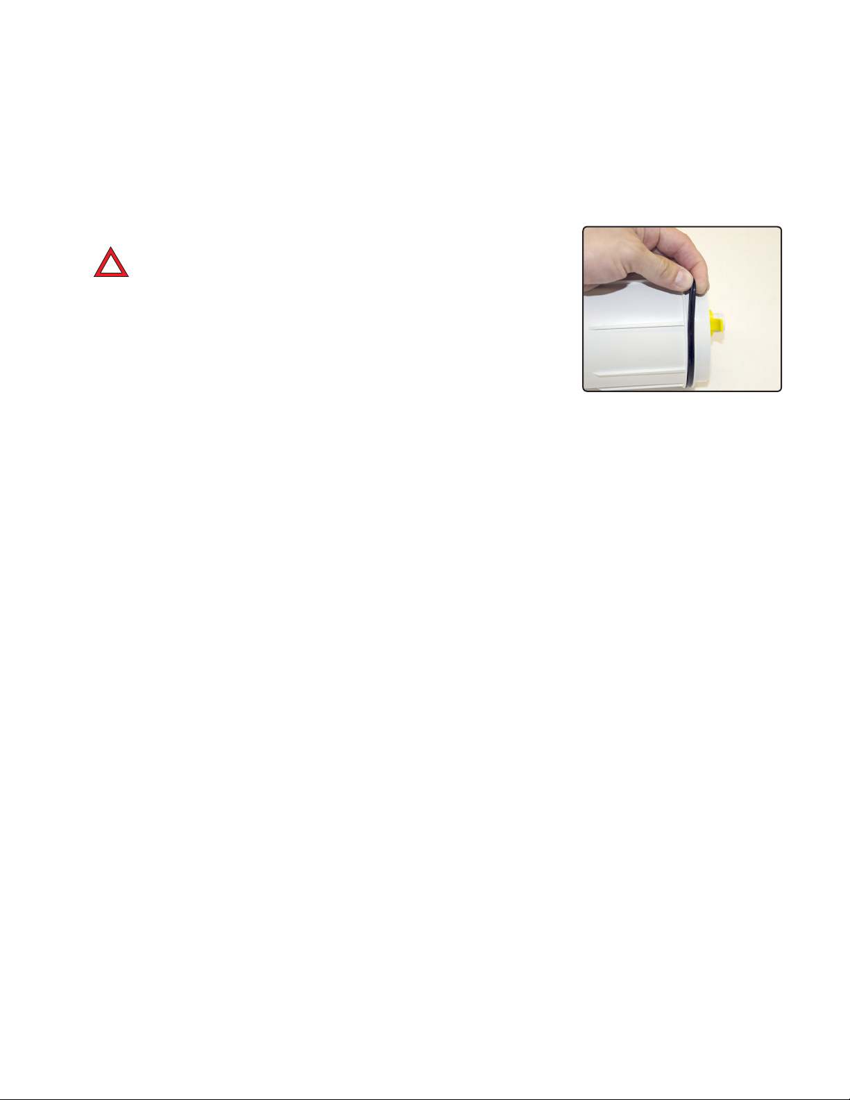
FILLING STEPS – PROPACK VERSION ONLY
!
DANGER: DO NOT perform this action unless you are certied
to do so.
1. Remove the Filter from the Canister. Inspect the quad ring for cleanliness/damage and clean/replace with a small amount of grease (Fig. 4.9).
2. Unscrew the yellow top nut and canister lid and inspect the meshes for
damage.
3. Remove any excess absorbent stains from the canister components
with warm, soapy water and then rinse in fresh water. Then allow it to dry.
4. Fill the canister in a well-ventilated environment. Raise the absorbent
barrel at least 200mm (8 inches) above the canister to allow dust to blow
away as you fill. Fill to the top of the canister, making sure absorbent is at
an even depth across the canister.
5. Pack the absorbent by tapping the sides for at least 1 minute.
6. Fill to the top again.
7. Pack the absorbent by tapping the sides for at least 1 minute
8. Refill with Absorbent to the top. Tap down as required until you can fit
the lid. Refit the lid and the spring (under the yellow nut).
9. Screw down the top nut.
10. Wipe any dust from inside the canister.
11. Look into the Canister head and run your finger around the sealing
face for the quad-ring removing any debris.
12. Insert the filled Filter into the Canister.
13. Refit the Right Hand end cap.
14. Dispose of old absorbent as normal household waste. Do not leave it
lying around for animals to ingest.
Fig. 4.9
Filling instructions are also found on the side of the canister tube.
FILLING STEPS – PRE-PACKED VERSION ONLY
1. Remove the Filter from it sealed packaging.
2. Inspect the quad ring for cleanliness/damage
3. Apply a small amount of grease to the quad ring.
4. Wipe any dust from inside the canister.
5. Install the filter.
6. Refit the Right Hand end cap.
7. Dispose of old absorbent filter as normal household waste. Do not leave
it lying around for animals to ingest.
86 |
Page 93

POST DIVE
During a diving sequence, it is important that a small amount of daily maintenance is undertaken. These fall into 5 categories:
1. Care of oxygen and CO2 sensors
2. Loop cleaning
3. Recharging
4. Cylinder filling
5. Absorbent changing
6. BCD
CARE OF OXYGEN AND CO2 SENSORS
The Sensor Module (SM) is easily removed from the unit by removing the
Life Support System Module (LSS) and pulling the SM out. The SM carries
the three oxygen sensors and the CO2 sensor.
Post dive the CO2 filter (yellow cap) sponge should be replaced as detailed.
At the end of a days’ diving the complete SM should be removed (and the
LSS cap refitted) and kept in a dry (low humidity) and ambient temperature environment. The CO2 filter cap should be removed for the non-diving
period.
4.2
LOOP CLEANING
After a dive the hoses should be removed and fresh water should be
flushed through the complete assembly and be allowed to drain out. To
remove excess water, push the hose corrugations together (like using a
concertina) to squeeze the water out.
Disinfect the unit as per the ‘Explorer Rebreather Maintenance Chart’,
PART 7 Section 4.
RECHARGING
Please see "Batteries" PART 1 section 2.
| 87
Page 94

CYLINDER FILLING
All dives must start with a full cylinder. All gas must be analyzed prior to
use.
ABSORBENT CHANGING
Absorbent must be changed in accordance with the section in the manual
titled ‘The Absorbent Filter’.
BCD
Drain any water from the BCD. Re-inflate and the operate dump valves and
the inflator to confirm everything is OK.
88 |
Page 95

COMPLETING PRE-DIVE CHECKS
PURPOSE
These tests are designed to:
1. Check that all functions of the EXPLORER have a high likelihood of operating correctly
2. Detect assembly errors
3. Detect breathing loop errors
4.Advise the user of system measurements that are outside correct
operating parameters including:
a. High Pressure readings too low
b. High Pressure readings dropping too quickly – possible leaks
c. Battery Levels
d. PPO2 partial pressure of oxygen in the breathing loop
e. Calibration of PPO2/CO2 sensors performed correctly
f. Ensure the CO2 absorbent is functioning correctly, and the filter is
inserted correctly and is sealed
THE COMPLETE (PASS MODE) PRE-DIVE SEQUENCE
The complete sequence is detailed on the following page. This sequence
assumes all tests pass OK and no Pre-dive has been conducted within one
hour. The full screen chart is available on the CD enclosed with the product. An APP for any Android device is available at http://hollis.com/support.
asp and on the enclosed CD with your EXPLORER.
4.3
| 89
Page 96
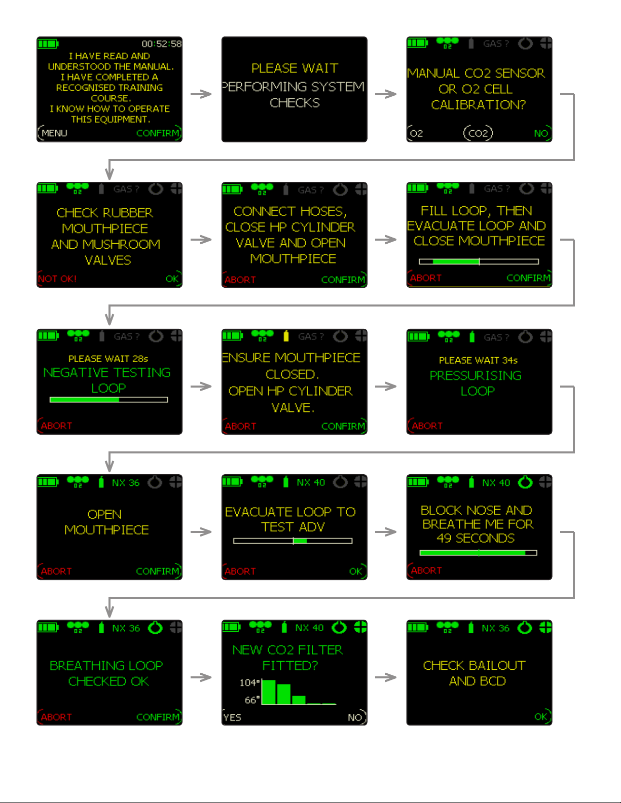
Title
subtitle
90 |
Page 97
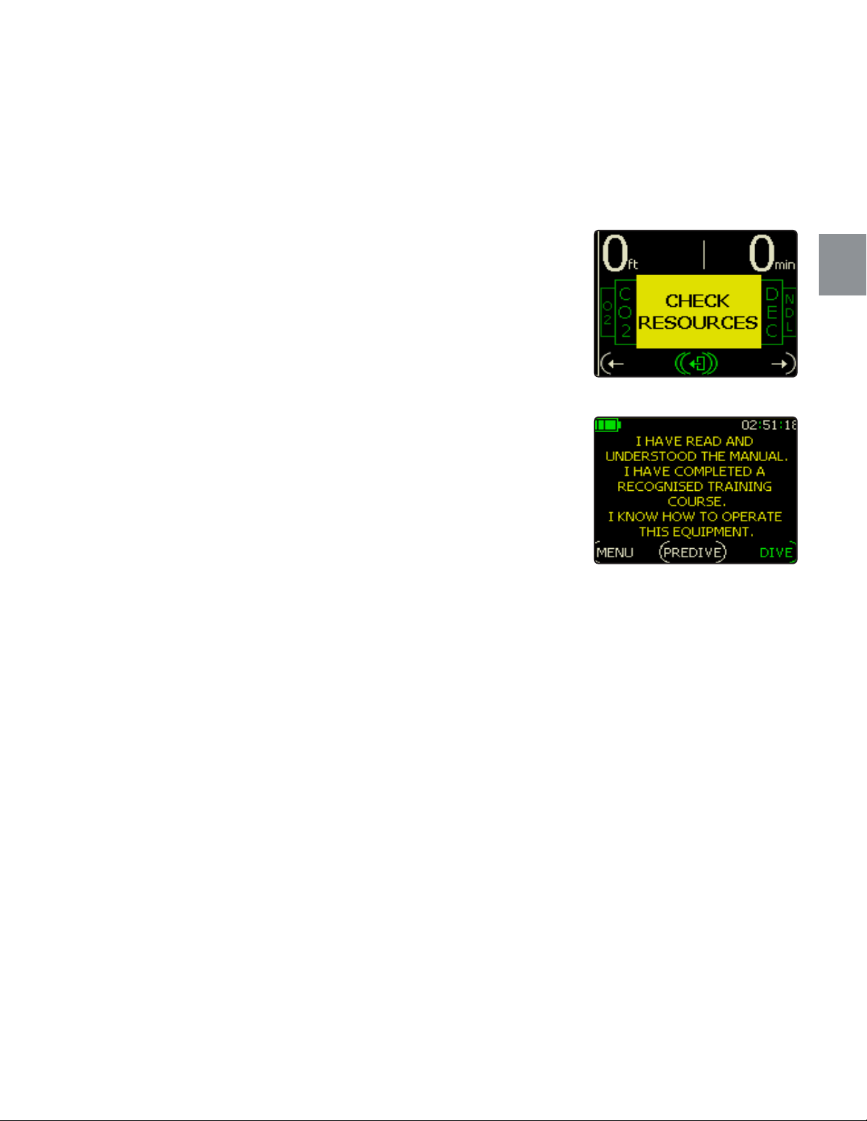
From the dive screen, each resource must then be checked (Fig. 4.10).
Once you have checked each resource the STATUS display will show
SYSTEM OK.
DIVING WITHIN 2 HOURS OF A SUCCESSFUL PRE-DIVE SEQUENCE
If you start a dive within two hours of a successful Pre-dive being conducted then EXPLORER will display the following Startup screen (Fig. 4.11).
Now you can simply select DIVE or go through the Pre-dive sequence
again by selecting PREDIVE.
4.3
Fig. 4.10
Fig. 4.11
| 91
Page 98
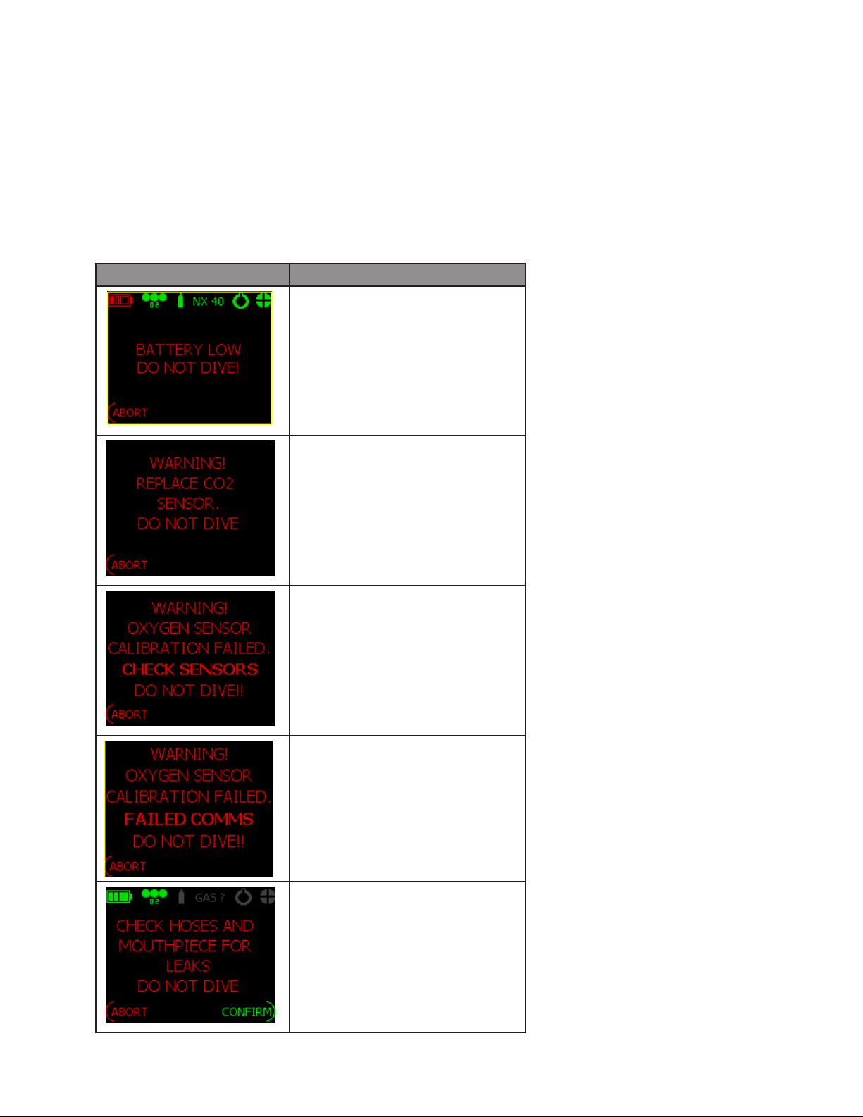
User Fault Finding & Testing
PRE-DIVE PRIMARY ERROR MESSAGES & THEIR MEANINGS
Message Meaning
The batteries in the EXPLORER
must be charged prior to diving.
CO2 sensor is unable to calibrate
and must be replaced or removed
(the 5 minute pre-breather system
will be activated).
O2 sensor(s) unable to calibrate
and must be replaced and/or their
connectors cleaned.
O2 sensor(s) unable to calibrate or
failed LSS/Sensor Module.
Recharge unit and try again. Return
to dealer if problem persists.
Negative test failed. Ensure Cylinder is attached. Ensure Mouthpiece is fully in OC mode. Fill loop
until vent valves exhausts then
attempt negative test again.
92 |
Page 99
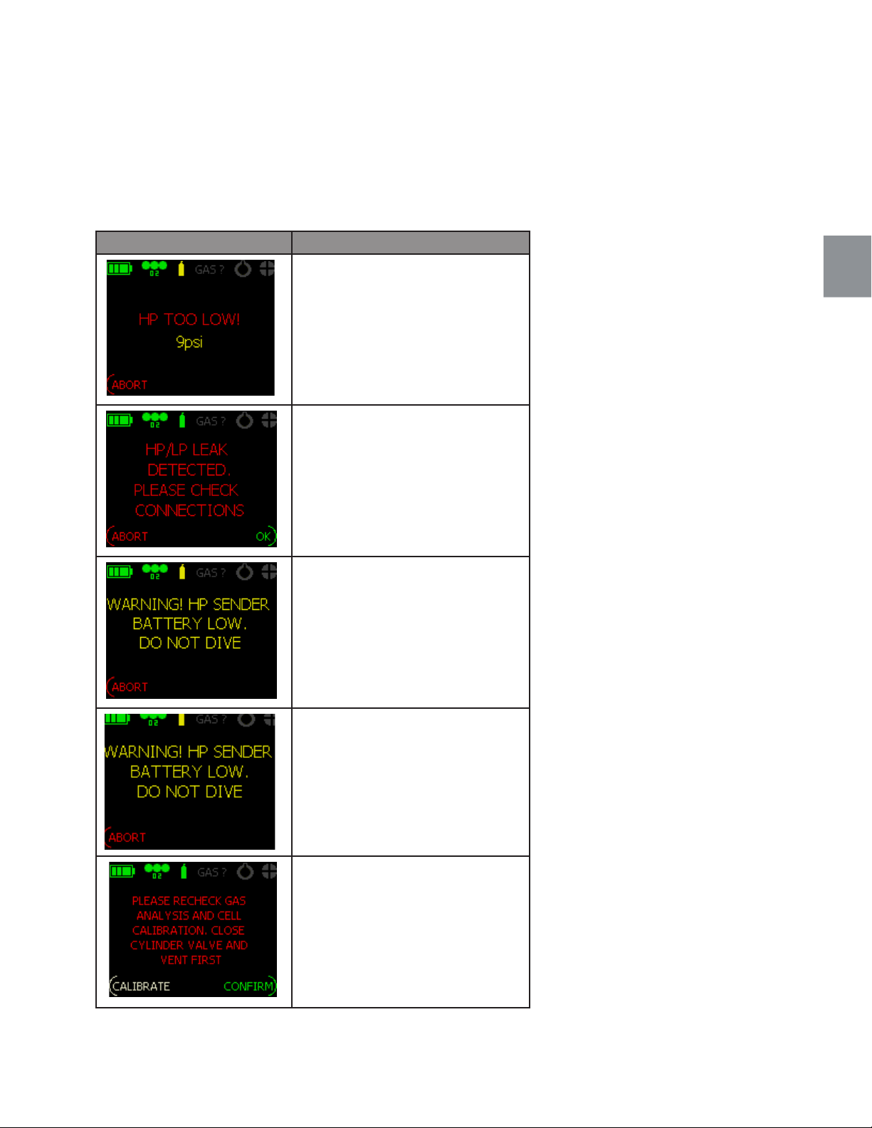
Message Meaning
Low HP gas in dive cylinder.
If HP reduces by >50bar/735 psi
or does not reduce by at least
5bar/73.5 psi.
Make sure cylinder valve is fully
open.
Check cylinder size is correct in
DEFAULT GAS Menu. Do not use
unlisted cylinders. Submerge unit
and look for LP/HP leaks, BC inflator failures etc.
4.4
Wireless HP sender battery is low.
Analyzed gas is not what is
expected by the DEFAULT GAS
setting.
Analyze gas and check setting.
| 93
Page 100
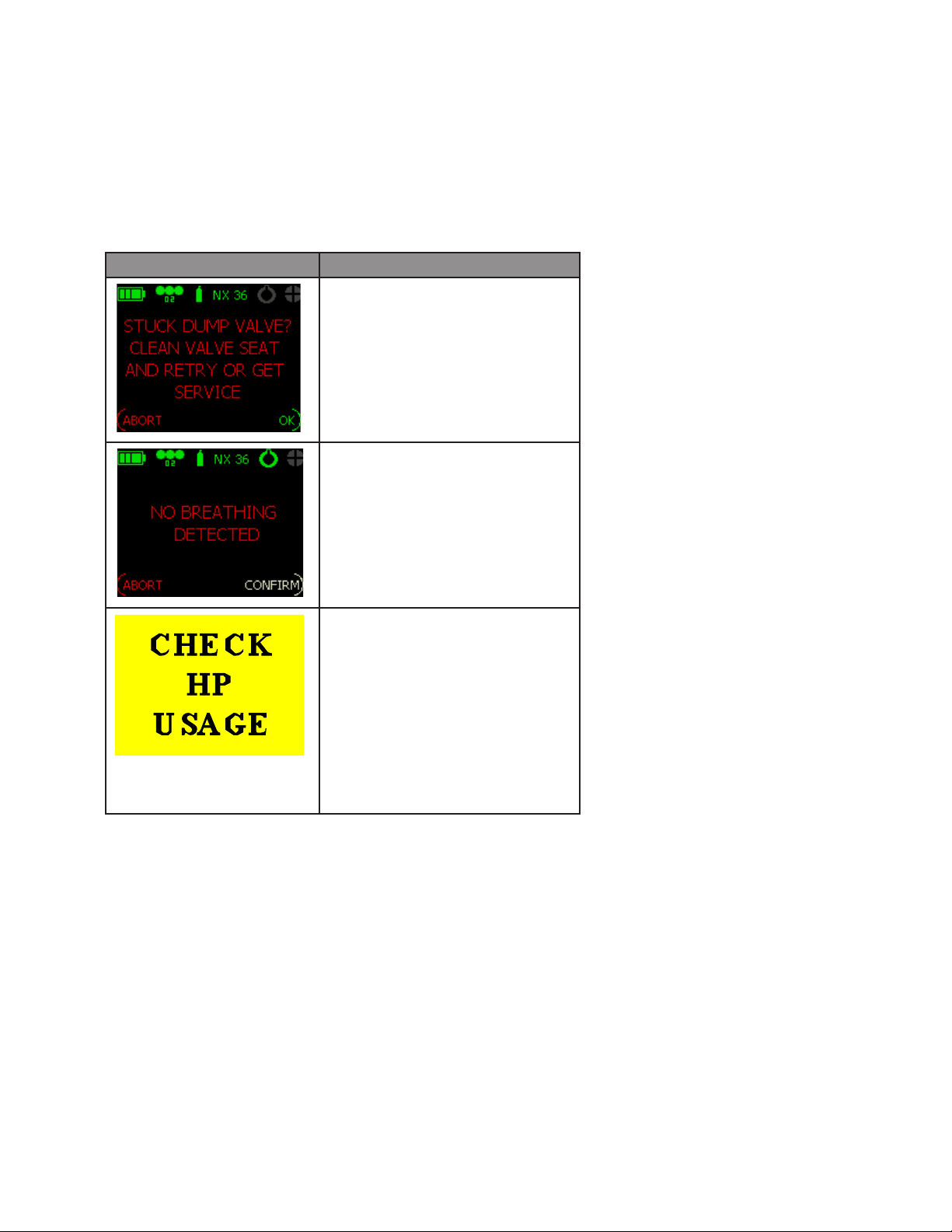
Message Meaning
The LCV and OPV are not venting at the correct pressure. Flush
valves with fresh water and repeat
test. If the problem persists return
the unit to your dealer.
You have stopped breathing while
conducting a pre-breathe sequence.
Repeat the test. If the error persists return the unit to your dealer.
If the Predive sequence is completed, the STATUS window is
active, and you see the above
alarm, then HP usage is greater
than 1bar/min – 14.7 psi/min.
94 |
This could indicate a leak in the
HP or LP circuit (internal pipework), BC or BOV. Submerge to
locate the leak.
 Loading...