

Page 1

ST-4000
SIGNAL LEVEL METER
Page 2

Table of Contents
Features / Specifications
Keypad Illustration
…………...…………………………..……….. 2
Keypad Controls………….…………………….………….………. 2
Getting Started:
Powering the Meter………………………………….…...…… 3
Quick Use Instructions………….…………………….……… 3
Main User Instructions:
1 Meter Set-Up Features…………………………….....……..…….. 4
1.1 Auto Off Time……………………………………………... 4
1.2 Audio Set…………………………………..………….…... 4
1.3 Measurement Scale ……....……………………….…….. 4
2 Selecting CATV or VHF/UHF Channels………………………… 5
3 Configuring Channel Line Up…………………………..………… 5
3.1 Channel Plan…………………………………..………….. 5
3.2 Channel Edit…………………………………..…………… 5
4 Meter Calibration……………………………………….……..…..… 6
4.1 Correct CH db (Calibration)……………………....……... 6
4.2 Clear Correct (Restore Factory Calibration)…...…….… 6
5 Scanning Channels – Saving and Viewing Data…………….… 7
5.1 Scanning and Saving Data…………..……………….….. 7
5.2 Viewing Stored Data…………………………………….… 7
6 Measuring Signal Levels
6.1 Single Channel Signal Level Measurement - V, A or V/A 8
6.2 Frequency Based Signal Level Measurement…………… 8
Warranty…………………………………………………..……….. ... 9
………………………...…….………… 1
Page 3

FEATURES
* Select Channels 2 – 136 CATV (NTSC) * 12 Hour Rechargeable Ni-MH Battery
2 – 69 Off-Air (NTSC)
* Select Frequency 46-870 MHz * Auto Shut Off
* Measures Video, Audio, or V-A * Charging LED
dBmV or dBuV (selectable)
* Scan Selected Channels and Store Signal Level Data
SPECIFICATIONS
Frequency and Level
Range: 46 to 870MHz in 10 kHz steps
Resolution Bandwidth: 280KHz ± 50KHz
Channels: All user designated NTSC Channels
Level Range: -28 dBmV to +55 dBmV (32dBµV to- 115dBµV)
Accuracy: ±2.5dB
Input impedance 75
Wave detection Peak value
AUTO SCAN TESTING
Max Channel Scan: 135 Channels
Scan Range: All Frequencies: 46 to 870MHz
Scan Speed: 30 Channels/Min
Memory Groups 12 Groups (01--12)
OTHERS
Dimensions: 214mm x 94mm X 47mm
Weight: 1.4 kg (with charger)
Working Temperature: -10 to + 40
Display LCD: 16X2 LCD with back light
POWER
Battery: 7.2V/1.6AH Ni-MH
Power Supply / Battery Charger AC 110V/60Hz ±10%
Battery Life: 5 hours of continuous operation
Recharging Time: 12 hours
STANDARD ACCESORIES
Battery Charger: 1 pc
Carrying Case w/strap 1 set
Barrel Connector: G-F81F* 2 pcs
Operators Manual 1 copy
Each group stores up to 135 Channels
Quick Users Guide 1 copy
Electronic copies of the Users Manual & Quick Users Guide are available
on our website: www.hollandelectronics.com/support.html
1
Page 4
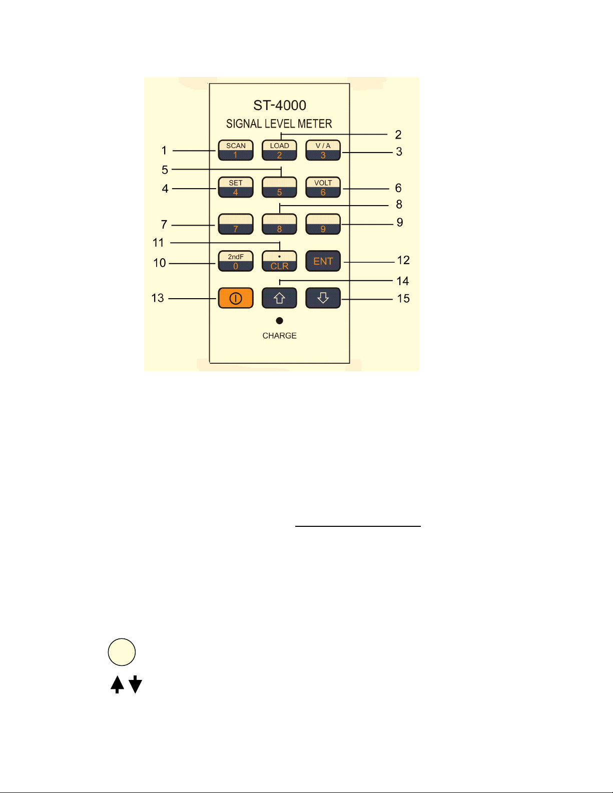
KEYPAD ILLUSTRATION
KEYPAD CONTROLS
1. Numerical 1 / 2nd Operation SCAN – Scan and save signal level values for selected channels
in a memory group
2. Numerical 2 / 2
3. Numerical 3 / 2
4. Numerical 4 / 2
5-9. Numerical 5-9 / Volt Function (keypad 6) Not Available on This Model
10. Numerical 0 / 2
11. CLR /
12. ENT Pressing ENT allows for entering desired function or setting
13. I On/Off – Turn meter power on or off
14-15. UP Arrow – Increase the displayed channel or frequency. Also used to navigate
16. LED Indicator AC Power / Battery Charging Indicator
. Pressing this key while in a menu screen will return to the previous menu.
nd
Operation LOAD - View data previously stored in a memory group
nd
Operation V/A – Select Video, Audio or V/A carrier display screens
nd
Operation SET – Access the meter Settings menu screens
nd
Operation Function Key – Pressing 2nd F activates the secondary
programmed function of the next key that is pushed
This key is also used as both a decimal point and the final key after entering a
frequency value, before pressing ENT.
through the Settings menu. DOWN Arrow - Decrease the displayed channel or
frequency. Also used to navigate through the Settings menu
2
Page 5

Getting Started
______________________________________________________________________
Powering the Meter
The ST-4000 can be powered either by the internal rechargeable Ni-MH batteries or by use of
the included power supply/battery charger.
A) Using the external AC power supply: Make sure that the available AC line
voltage is 110-120V, 60 Hz. Connect the DC output plug from of the adapter /
charger to the DC receptacle on the bottom of the ST4000 meter.
B) Powering the meter with internal batteries: In order for the ST4000 meter to
operate from the internal batteries, a sufficient charge must exist on the batteries.
The recommended time to fully charge the batteries is 12 hours. Only use the
power supply / battery charger included with the meter. The batteries charge
whether the meter is switched on or off. The Red LED on the meter will illuminate
whenever the power supply / battery charger is attached and plugged into an
110VAC source.
Warning: Use Only The Power Supply / Battery Charger Supplied With The Meter.
Use Of Any Other Will Void Warranty and Can Cause Damage Or Injury.
Quick Use Instructions
To become familiar with the basic operation of the meter it is suggested that the user initially try
the following:
1) Charge the batteries using the supplied power supply/charger unit.
2) Turn the meter on by pressing the On/Off key and check settings in the Set Up menu as
described in Section 1.
3) Check and set the meter to read either CATV or VHF/UHF channels as follows:
i) From any menu screen Press CLR then Press 2, then Press ENT. The display will
show CH002 if the meter is set for CATV channels or CH02 for VHF/UHF channels.
To switch back and forth between CATV and VHF/UHF channels, perform the
following steps below, otherwise skip to step 4:
ii) Press the On/Off key to turn the meter off
iii) Press and hold the SCAN key while pressing the On/Off key
iv) The meter has turned back on and switched between the CATV and VHF/UHF
channels. Repeating steps ii and iii will switch the selected channels again.
4) Carefully align the threads and connect the G-F81 type adapter to the RF Signal input port
on the meter. Hand tighten until the adapter is fully seated. Over tightening the adapter
with a tool can seriously damage the input port on the meter.
5) Connect the CATV or VHF/UHF signal source (cable line, antenna, etc) under test to the
meter.
6) Press “” or “” to scroll through the available channels and note the measured video
signal levels.
7) To switch and display the measured Audio level or V/A differential level values instead of the
Video level, press the 0/2
nd
F key and then press the 3/ V/A key.
3
Page 6

MAIN USER INSTRUCTIONS
1 Meter Set-Up Features
Each of the following set-up functions is activated by first pressing the 0/ 2ndF key followed by
the SET key.
1.1 AUTO OFF TIME
The meter can be set to turn off after 5 minutes of inactivity or to remain on continuously.
Press “” or “” to point “” to “Auto Off Time”. Press ENT key.
Use “” or “” to choose desired mode. Press ENT key.
LCD will display:
1.2 AUDIO SET
Enable or disable the speaker to monitor the audio while measuring audio carrier signal levels.
Press “” or “” to point “” to Volume Set. Press ENT key.
Use “” or “” to choose desired mode. Press ENT key.
LCD will display:
1.3 LEVEL UNIT
Select the desired measurement scale of dBV or dBmV
Press “” or “” to point “” to “Level Unit”. Press ENT key.
Use “” or “” to choose desired mode. Press ENT key.
LCD will display:
5 Minutes off
Always On
Audio On
Audio Off
dBµV Enable
dBm V Disable
4
Page 7

2 Selecting CATV or VHF/UHF Channels
The meter can be switched between CATV channels and VHF/UHF channels. To determine
how the meter is currently configured or to make a change, do the following:
From any menu screen Press CLR then Press 2, and then Press ENT.
Check to see whether the displayed channel is CH002 (CATV) or CH02 (VHF/UHF).
To switch back and forth between CATV and VHF/UHF channels, perform the following steps:
i. Press the On/Off key to turn the meter off
ii. Press and hold the SCAN key while pressing the On/Off key
iii. The meter has turned back on and switched from either CATV to
VHF/UHF or from VHF/UHF to CATV channels. Repeating steps i and ii
will switch the selected channels again.
3 Configuring Channel Line Up
The meter is factory programmed to read CATV channels 2-136 and VHF/UHF channels 2-69.
Customized CATV and VHF/UHF channel plans within these ranges can also be saved in the
“User Plan” mode.
In order to select or edit the “User Plan” channels, the meter must first be set to the proper
channel format (CATV or VHF/UHF). If you are unsure which channel format is currently
selected or want to change the selection, refer to Section 2.
3.1 CHANNEL PLAN
Select the factory programmed channel plans “NTSC CATV” or the custom “User Plan”
Press the 0/2
Press “” or “” to point “” to “Channel Plan”. Press ENT key.
Use “” or “” to select the desired plan. Press ENT key.
LCD will display:
NTSC CATV
User defined Channel Plan
User PLAN
3.2 CHANNEL EDIT
Specific channels can be included or removed from the “User Plan”.
Press the 0/2
Press “” or “” to point “
Use “” or “” to select the desired channel. Pressing SET will toggle the display between
ON (including the channel in the plan) and OFF (eliminating the channel from the plan).
Press “” or “” to move to the next channel. Press ENT key.
Repeat the process with the SET key to toggle the channel ON/OFF setting
LCD will display:
Press key “SET” to edit
Press “SET” Edit
nd
F key and then the SET key.
nd
F key then the SET key.
” to “Channel Edit”. Press ENT key.
CH02 ON
NTSC Channel Plan – CATV or VHF/UHF
Select CH02 (ON) or don’t select (OFF)
5
Page 8

4 Meter Calibration
This meter has been factory calibrated. The user can recalibrate each individual channel by
connecting a CATV or VHF/UHF signal source with a known RF level to the meter input. The
factory calibration of all channels can also be restored at any time.
4.1 CORRECT CH dB (Calibration)
Adjust the displayed power level to match the input signal source level as follows:
Press the 0/2
Press “” or “” to point “” to “Correct CH dB”. Press ENT key.
Use “” or “” to adjust the displayed LEVEL value to match the input signal source.
Press SET to save the calibration. Press “ ” or “” and repeat for the next channel.
LCD will display:
CH to correct Video Carrier (V) Current correction (offset) value
CH02V +0.0dB
CH02 Video Carrier modified value (offset)
LEVEL 15.6dBmV
Measured Level value after modification
The displayed CH02V is the channel to be modified. The displayed mode is the video carrier.
The calibration adjustment is applied to both the video carrier and audio carrier readings.
NOTE: User is not able to modify audio carrier calibration independently.
Press CLR when all channel calibration changes have been completed
4.2 CLEAR CORRECT
Restore to the factory preset calibration values.
Press the 2
Press “” or “” to point “” to “Clear Correct”. Press ENT key.
LCD will display:
NOTE: If you have entered this menu by error and do not want to restore the factory
calibration values, press CLR key to escape the operation and return to testing mode
Press ENT key again to confirm and restore the factory preset calibration values.
This function will take a few seconds. All the modifications are cleared (correct value =0dB)
Clear Correct
nd
F key then the SET key.
nd
F key then the SET key.
Press “ENT”
6
Page 9

5 Scanning Channels – Saving and Viewing Data
Channels within the CATV or the VHF/UHF tables can be scanned and saved into one of the
meter memory groups and then viewed at any time.
Prior to scanning channels there are two set-up steps:
1 The meter should be set for either CATV or VHF/UHF channels – Refer to Section 2
2 The customized “User Plan” or the factory preprogrammed channel plan “NTSC CATV”
should be selected - Refer to Section 3
5.1 SCANNING and SAVING DATA
The designated channels within the CATV table or the VHF/UHF table can be scanned and
saved into one of the memory groups.
Press the 0/2
nd
F key and then the SCAN key
LCD will display:
Scan groups
Scan No.00
NTSC VHF/UHF 1-6
Press “,, ENT”
NTSC CATV 7-12
Press “” or “” to select a storage location - Groups 01-06 (VHF/UHF) or 7-12 (CATV).
After selecting the desired Group, press the ENT key to confirm.
The meter will now scan and save all channels. To escape operation, press CLR key.
Note: Data stored into any memory group during automatic scanning can be overwritten by
running automatic scanning again.
5.2 VIEWING STORED DATA
Data measured and stored into a memory group during a SCAN operation can be viewed.
Press the 0/2
nd
F key. Press the LOAD key
LCD will display:
CH02 V LOAD01
LEVEL 18.7dBmV
Stored video carrier signal level
CH No. 2 Video from Group:01
Press the “” or “” key to select the memory group to display. Press ENT key
Press the “” or “” key to view all scanned channels. To escape press CLR key.
If no data is stored,
LCD will display:
No Channel Saved
No Channel Level Stored
(Meter will auto escape to channel measurement mode)
7
Page 10

6 Measuring Signal Levels
6.1 SINGLE CHANNEL SIGNAL LEVEL MEASUREMENT - VIDEO, AUDIO or V/A
(Select CATV or VHF/UHF channels first – Refer to Section 2)
Press the 0/2
To change between Video, Audio and V/A, press the 0/2
Press the “” or “” key to view desired channel.
LCD will display:
CH002V 55.25MHz
LEVEL: 18.7dBmV
VIDEO Test Mode AUDIO Test Mode V/A Test Mode
6.2 FREQUENCY BASED SIGNAL LEVEL MEASUREMENT
To measure the signal level of a specific frequency between 46MHz and 870MHz
Use the numerical keys and the CLR/ . decimal point key to enter the desired frequency.
Press the ENT key to confirm.
LCD will display:
FREQ 87.50MHz
LEVEL: 10.0dBmV
nd
F key. Press the V/A key to enter this measurement mode.
CH002A 59.75MHz
LEVEL: 5.0dBmV
Selected Frequency
Measured Signal Level
nd
F key and then the V/A key.
CH002V 55.25MHz
V/A: 13.7 dBmV
8
Page 11

HOLLAND ELECTRONICS LLC
LIMITED WARRANTY
Holland Electronics LLC warrants that the product enclosed with this Limited
Warranty statement will conform to the manufacturer’s specifications and be free
of defects in the workmanship and material for a period of one-year (1) from the
date of original purchase
WARRANTY PROCEDURE:
If the product appears to be defective contact Holland Electronics LLC at (805)
339-9060. We will analyze the problem and offer solutions to prevent removing
the unit from service. If no solution is found, and the unit must be returned for
repair, you will be issued a Return Authorization (RA) number.
Holland Electronics LLC will, at its option, repair or replace the defective unit
under warranty, without charge for parts or labor. This repair will be subject to
charges if signs of tampering or misuse are detected. Incoming shipping costs
will be the customer’s responsibility. Returns will not be accepted without an RA
number.
The warranty and remedy provided above are exclusive and in lieu of all other
express warranties and unless stated herein, any statements or representations
made by any other person or firm are void. The duration of any implied
warranties of merchantability or fitness for a particular purpose on this product
shall be limited to the duration of the warranty set forth above. Except as
provided in this written warranty, Holland Electronics LLC shall not be liable for
any loss, inconvenience, damage, including direct, special, incidental, or
consequential damages, resulting from the use or inability to use this product,
whether resulting from breach of warranty or any legal theory.
Some states do not allow limitations on how long an implied warranty lasts and
some states do not allow the exclusion or limitation of incidental or
consequential damages, so the above limitation and exclusion may not apply to
you.
The warranty gives you specific legal rights, and you may also have other rights,
which vary from state to state.
To arrange for warranty service: Call Holland Electronics LLC (805) 339-9060
Return Address with appropriate Return Authorization Number:
2935 Golf Course Drive
Ventura, CA 93003
.
9
 Loading...