

Page 1

Forward Optical Receiver
CATV OPTICAL RECEIVER
Operation Manual
Operation Manual
Ver. A1
- 1 -
Page 2

Forward Optical Receiver
Operation Manual
TABLE OF CONTENTS
TABLE OF CONTENTS ....................................................................................................2
Chapter 1 Introduction......................................... .............................................................3
Chapter 2 Installation................................................... .....................................................8
Chapter 3 Operating Instruction.....................................................................................10
Chapter 4 LCD Display and Operation Procedure.........................................................13
Chapter 5 Status Monitoring and communication interface...........................................17
Chapter 6 Maintenance and Repair ................................................ ...............................20
- 2 -
Page 3

Forward Optical Receiver
Operation Manual
Chapter 1 Introduction
Overview
The CATV fiber optic receiver uses a high linear InGaAs PIN diode as light detector, converting the optical
signal from transmitter into RF signals. The RF signals are then distributed to the end users. There are two
front-end opt ical rece ivers in th e units, and s hare the sam e RF signal am plifier, two receiv ers could prov ide
redundancy function in network. The main applications are as follows:
• Head-end broadcasting
• Head-end to head-end program exchange
• Transmission of video and sound through Hybrid Fiber Coaxial (HFC) networks
In order to achieve maximum performance and confidence by the customer, we detail the characteristics,
applications, and operating instructions in the following chapters. We expect to satisfy the needs of the
customer and provide quality service.
Features
19” 1U height standard enclosure, front LCD display
45 ~750/860 MHz bandwidth
Redundancy A/B switch receiver
Automatic Gain Control / Manual Gain Control
Microprocessor control & Monitoring
RS232/RS485 control interface
High performance value
+1dB ~-3dB Range Adjustable Slope
- 3 -
Page 4
r
Forward Optical Receiver
Operation Manual
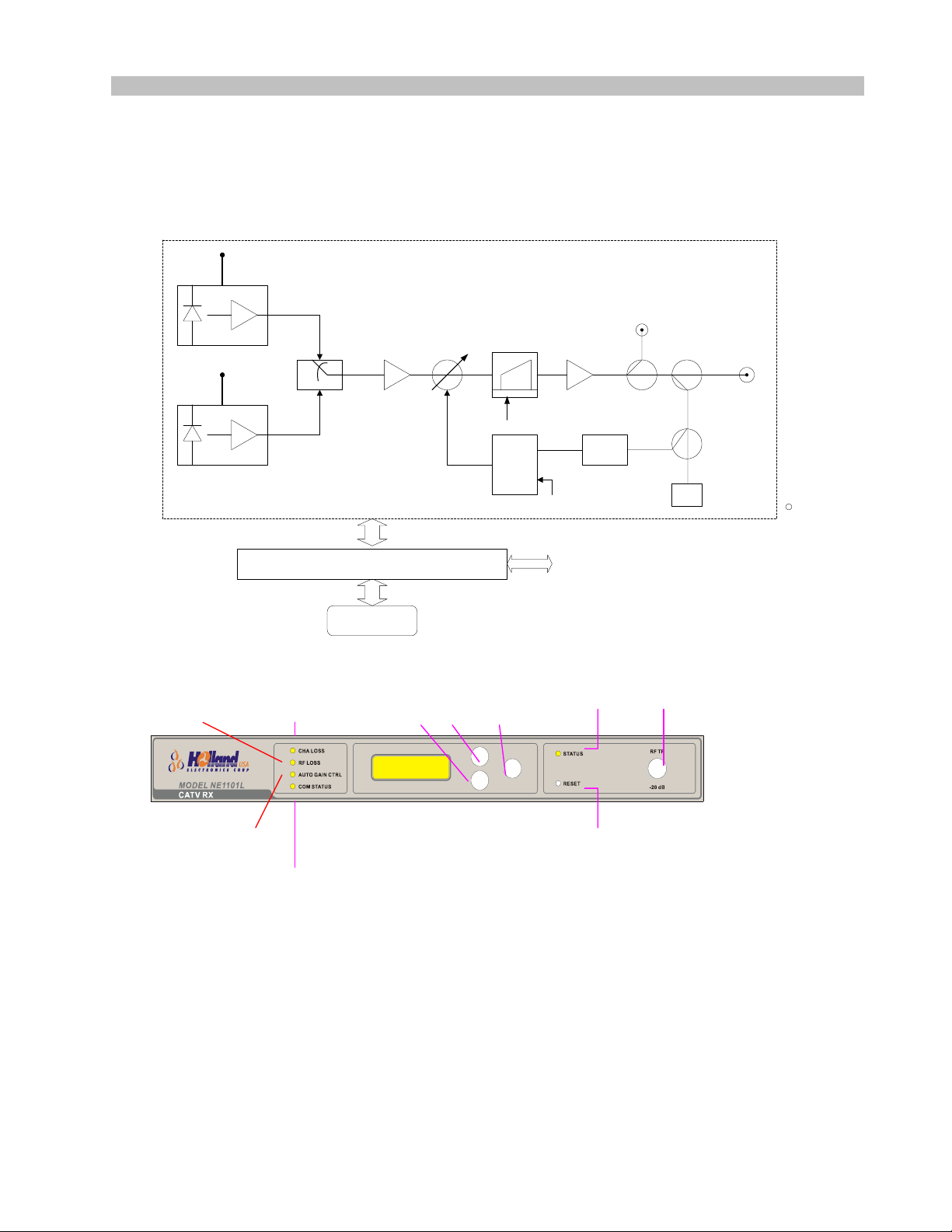
Product Description
FRx Block Diagram
FRx Function Block Diagram
PD_A
monitor
Rx_A
Rx_B
Front Panel
RF loss
PD_B
monitor
Ch A Loss
RF
Amp
u-controller
LCD
Button Button Button
Attenuator Slope
Slope
CTL
S
RF
Amp
Pilot Tone Detect
AGC
Communication
TP -20dB
RS485
Powe
RF
Output
RF Level
RF MONITOR
Auto Gain Ctrl
Reset
Com Status
- 4 -
Page 5
p
A
Forward Optical Receiver
Indicator/Control Description
Power
Ch A Loss
RF Loss RF signal power less than RF power threshold.
Auto Gain Ctrl
Com Status
Button Rest Reset System, Note: it will restart all system.
Button UP Scroll up
Button DN Scroll up
Button ENT Select highl ighted item on LCD display
RF MONITOR
–20dB
Operation Manual
Main power indicator
Green – AC Power On
OFF -- AC Power OFF
Ch A Optical Power
OFF – Optical input power > Channel A optical power low
threshold
RED Flashing – A port Optical input < Ch annel A optical power low
threshold
Displays status of the gain control mode
GREEN – AGC mode
OFF – MGC mode
Displays status of RS485 or RS232 connection
GREEN – Data transmit or received
F-type female connector, Monitoring output port signal, Measured
value is 20 dB below actual value. Accuracy to ±1 dB.
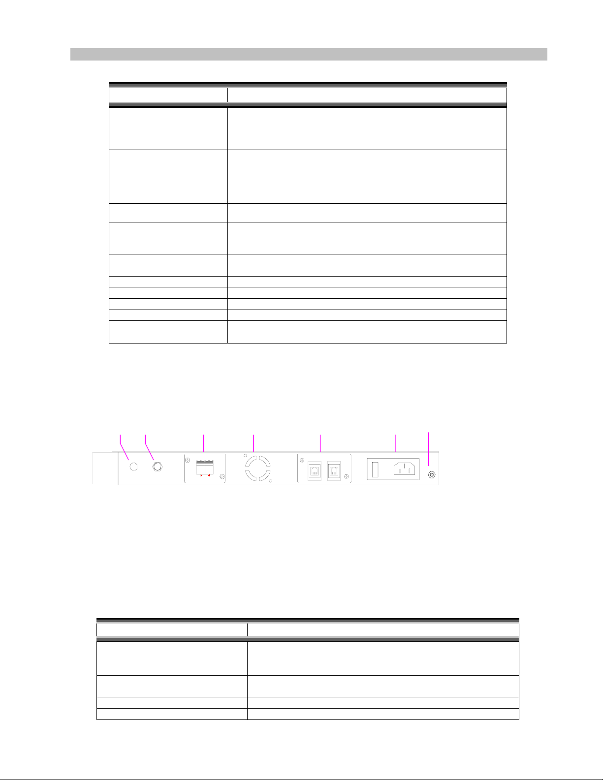
Rear Panel
Dummy
Hole
AC Power In(ON/OFF Switch,
Plug, Fuse)
RS-485 Interface
Dummy FAN Hole
A/B Port Optical Input
Dummy
FAN
Hole
RS485
Interfac
RS-485
AC
Power In
90V~220V 50/60Hz
FUSE 3.15A
ON
OFF
Groundin
g spacer
RF
Output
/B
Port
Optical
OPTICAL
BA
Connector/Control Description
AC power plug and main power switch. Fuse is rated 250V、
3.15A. For inspection or replacement, press down on the fuse
cap and turn to loosen.
Provides connection to an external computer through RS-485 for
monitoring and configuration setup purposes
Dummy: Not used in this type
tical Input connectors are SC/APC type. For connection, use
O
- 5 -
Page 6
Forward Optical Receiver
RF Output
Dummy Hole
Operation Manual
same type of connector.
RF signal Output Port; 75Ω F type female connector
Dummy: Not used in this type
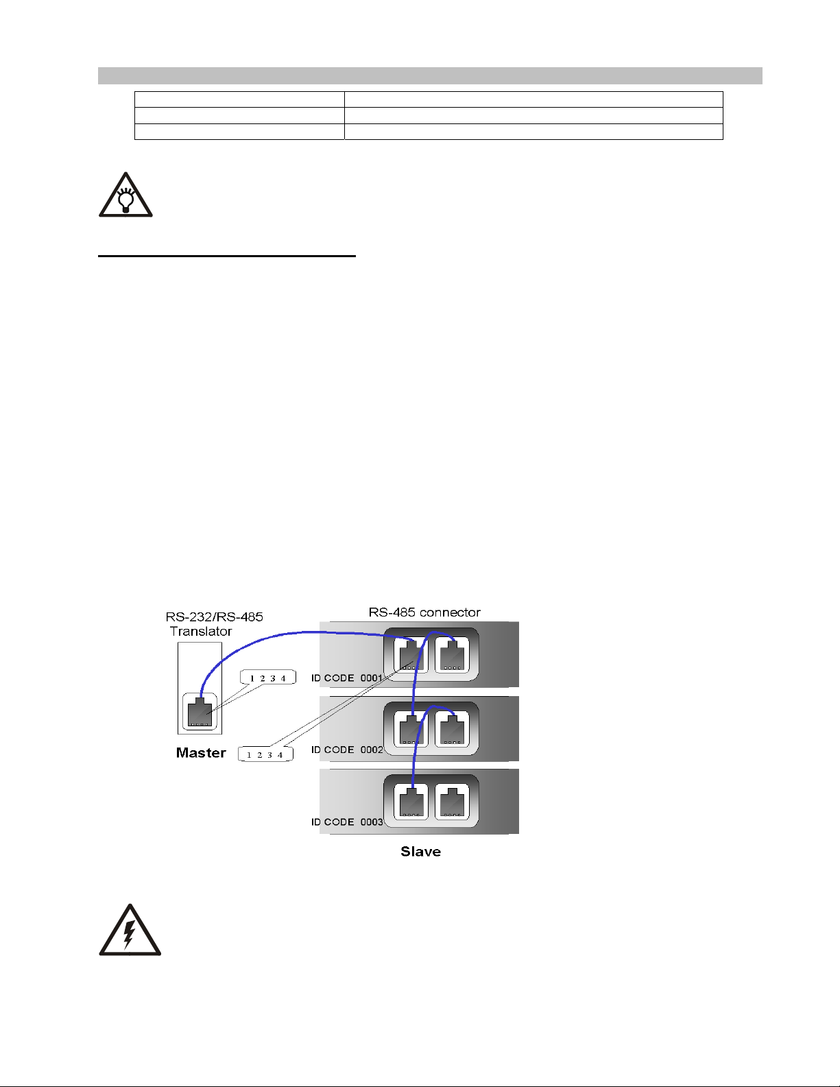
RS-485Interface Pin Definition
This RS-485 is full duplex type, so master and slave pin assignment is not the sa me. The connector definition
should be as following.
Master:(PC side)
1、 Receive+
2、 Receive3、 Transmit4、 Transmit+
Slave:(TX side)
1、 Transmit+
2、 Transmit3、 Receive4、 Receive+
Please make sure AC power is off when replacing new fuse.
- 6 -
Page 7

Forward Optical Receiver
Operation Manual
Mechanical Information
OPTICAL
BA
RS-485
90V~220V 50/60Hz
FUSE 3.15A
ON
OFF
- 7 -
Page 8

Forward Optical Receiver
Operation Manual
Chapter 2 Installation Procedure
Checklist
Parts Qty
Hanger 1 set
AC power cord 1
Installation
The following are procedures to be followed in the installation of Rack Mount Forward Receiver(called as FRx in the
following description):
1. Before installing the FRx, check to make sure that enough space is provided for air circulation especially in the
Heat Sink portion of th e FRx.
2. Check the power plug of the supply and proper grounding to avoid damage to the FRx.
3. Conn ect the AC power cord.
4. Connect the 「RF Output」 coaxial cable.
5. Lift the eye-safety shutter from the rear panel 「Optical Input」 fiber connector, and connect the jumper optical fiber.
Before connection, clean the connector and make sure that the connector type is SC/APC.
6. Ch A Port of Optical input port is recommended as the Main loop. And use the Ch B Port as Backup loop.
Caution: Direct eye exposure to laser beam may cause physical damage,
- 8 -
Page 9

Forward Optical Receiver
Operation Manual
Cleaning Fiber Connectors
1. Use a lint-free cloth (3 cm x 3 cm)
2. Moisten one-half of the lint-free cloth with >90% pure ethyl or alcohol, and gently wipe the connector end face
3. Use the other half of the lint-free cloth to gently wipe the connector end face, then rapidly shake the connector
4. Wait until dry to insert connector into the adapter
5. Caution: do not use any compressed air to directly blow onto the connector end face to avoid damage by dust
particles
Caution: Direct eye exposure to laser beam may cause physical damag e.
- 9 -
Page 10

Forward Optical Receiver
Operation Manual
Chapter 3 Operation Procedure
The following are procedures for the normal operation of t he FRx :
1) Switch the AC Power switch located on the rear panel to the ON position; the LED indicator for [POWER] on the
front panel will light up to indicate AC Power is connected.
2) Inspect the front panel [Ch A Loss] LED indicator.
Operation range of optical input power is from –6dBm to +3dBm , when the optical power large than –3dBm ,
the Output RF level could reach the default output level 96dBuV per channel when 77 channel load and
OMI=3.6%.
Under normal conditions, the LED should be off.
A flashing red light indicated abnormal Optical operation that can be caused by:
a) Ch A Optical Input Power lower than optical loss threshold.
b) Receiver module inside of the FRx work abnormally.
3) Inspect the [RF Loss] LED indicator.
Under normal conditions, the LED should be off.
A flashing red light indicates abnormal RF Output conditions, usually low output signal level.
4) Inspect the [Auto Gain Ctrl] LED indicator.
OFF: Operating in MGC Mode
Green: Operating in AGC Mode
Note: 1.There is two modes on AGC operation, one is detect Pilot signal, and
other is composite RF power feedback control. Before operation, please
select the AGC mode on “SETTING” menu.
2.Pilot tone mode used with Pilot Tone 10.7MHz ±100KHz coming from the
Trans mitt er. If there is no this feature in transmitter, please select RF
AGC or MGC control mode.
5) Check Optical Input Power in the LCD panel, 0 dBm is recommended.
6) Adjust the RF output level by using the front panel [SETTING] page. RF power operate in 96dBuV per channel
when 77 channel which have flat frequency response , if Channel number is higher , user could operate
level per channel .Keep the total composite power to maintain the distortion performance .
- 10 -
lower RF
Page 11

Forward Optical Receiver
Operation Manual
Note: RF output adjusting please refer the following page [LCD/LED Display User
Interface].
7) Adjust RF output slope to compensate the network loss in higher frequency.
- 11 -
Page 12

Forward Optical Receiver
Operation Manual
Chapter 4 LCD Display and Operation Procedure
LCD/LED Display User Interface
(LCD: Scrolling M enu)
OPT CHA 0.50 mW
OPT CHB 3.50 mW
RF LVL + 0.02 dB
GAIN CTRL LVL 2.5V
12V CURRENT 1.5 A
24V CURRENT 2.1 A
ENT
OPT CHA 05.0 mW
OPT CHB 05.0 mW
ENT
RECEIVER ST A TUS
RECEIVER SETTINGS
RECEIVER ALARMS
Up
RETURN TO MAIN MENU
RECEIVER STATUS
RECEIVER SETTINGS
RECEIVER ALARMS
RETURN TO MAIN MENU
RECEIVER STATUS
RECEIVER SETTINGS
RECEIVER ALARMS
RETURN TO MAIN MENU
RECEIVER STATUS
RECEIVER SETTINGS
Dn
RECEIVER ALARMS
RETURN TO MAIN MENU
24V DC 23.9 V
12V DC 11.9 V
Forward Rx
Forward Rx
FIBER OPTI C
FIBER OPTI C
RECEIVER
RECEIVER
TURN TO MENU
ENT
Dn
Up
Dn
Up
Dn
Up
ENT
ENT
ENT
ENT
ENT
1. MSG#1 is displayed for no alarm
2. Automatic switch to this screen wh en al arm occurs
3. Table 1 shows messages for various alarm events
5V DC 5.0 V
ID CODE 0A21
FIRMWARE VER 1.01
ENT
RETURN TO PREV. MENU
Dn
Dn
GAIN CONTROL = AGC
AGC MODE = RF
GAIN LV L SET. = 1 68
SLOPE LVL SET. = 66
CHA THRESHOLD = 020
CHB THRESHOLD = 015
SHOW CHB ALARM= NO
OPT LVL UNIT = dBm
SWITCH MODE =MANU
OPT CHANNEL = CHB
FACTORY PRESET
RETURN TO PREV. MENU
ALARM MESSAGE
ENT RETURN TO PREV. MENU
Please note:
due to space constraint of LCD screen, some words are abbreviated.
Such as: LVL – LEVEL , VER – VERS ION , PREV. – PREVIOUS ,SET. – SETTING
OPT – OPTICAL , CHA - CHANNEL A , CHB - CHANNEL B
Up
Up
UpDn
TX ALARMS (M9)
ENT
ENT
AGC
MGC
SELECT ENTRETURN
(AGC MODE)
GAIN LVL SET. = 168
ADJUST ENT RETURN
SLOPE LVL SET.= 66
ADJUST ENT RETURN
CHA THRESHOLD = 01 5
ADJUST ENT RETU R N
CHB THRESHOLD = 015
ADJUST ENT RETURN
YES
NO
SELECT ENT RETURN
mW
dBm
SELECT ENT RETURN
AUTO
MANUAL
SELECT ENT RETURN
CHA
CHB
SELECT EN T RETURN
ALL SETTINGS TO
FACTORY PRESET
YES
NO
SELECT EN T RETURN
GAIN CONTRO L
GAIN LEVEL SET TING
(AGC MODE OR MGC MODE )
SLOPE LEVEL SETT ING
(AGC MODE OR MGC MODE )
CHA THRESHOLD SETTING
CHB THRESHOLD SETTING
CONTROL CHB ALARM SETTING
SETTING OPTICAL POWER UNIT
SWITCHING MOD E
OPTICAL CHANNEL SELECT
(APP E AR ONL Y IF A/B SW. MODE IS IN ‘MANU AL’ MODE’)
FACTORY PRE S ET
Forward Rx
BUTTONS
ENT
AGC MODE
RF LEVEL
PILOT LEVEL
SELECT ENTR ETURN
(RANGE= 0 ~ 255)
(RANGE= 0 ~ 255)
(RANGE= 0 ~ 255)
(RANGE= 0 ~ 255)
▲ ▼
LCD Display Contents & Operation
1、Main Screen
When the Receiver Power on, it will be on th e main screen. Dur ing system operation, the displayed information w ill be
renewed continuously, to get more detailed information press ENT to access the MAIN MENU.
Display Item Description
Optical Ch A xxmW Receiver A input optical power
Optical Ch B xxmW Receiver B input optical power
- 12 -
Page 13

Forward Optical Receiver
Operation Manual
2
Main Selection Screen
、
At the main screen press the ENT key to ent er into the [MAIN MENU], then use the UP/DOWN keys to select the
following options:
Option Description
STATUS Present status of the Receiver
SETTINGS Settings screen
ALARMS Alarms screen
Return to Main Menu Return to main screen
3. STATUS selecti on screen
Selection Description
Optical A Receiver A input optical power
Optical B Receiver B input optical power
RF level Displays RF output level that relative to reference level.
Gain control level
Power Supply
Operating
Information
Displays Voltage control attenuator voltage, the upper bond would be 9.5V. The
Voltage higher means attenuation loss is lower.
Displays 12VDC supply, +5VDC current supply and -5VDC current supply
Displays software version and other reference information
4. SETTINGS selection screen
Selection Function Description
- 13 -
Page 14

Forward Optical Receiver
Gain Control Gain Control Select AGC or MGC
AGC mode Select RF AGC or Pilot tone AGC
AGC Level Automatic Gain Control Level Adjust AGC reference level
MGC Level Manual Gain Control Adjust MGC reference level
Slope level RF response slope control Adjust Slope from –1dB to +3dB.
CH A threshold
CH B threshold
Show CH B alarm CH B optical power alarm active
LD PWR UNIT OPTICAL POWER UNIT SELECT mW or dBm
Switch mode A/B switch mode
Operation Manual
There are two AGC mode could be
selected, one is pilot tone AGC, it could
detect the 10.7MHz pilot signal from
transmitter, and feedback control
attenuator, other is RF AGC, it detect
composite power of output RF signal
feedback control.
Adjust CH A optical power threshold. If
CH A optical power low threshold
setting
CH B optical power low threshold
setting
optical power lower than setting value, it
would trigger alarm and A/B switch select
B channel, if A/B switch active.
Adjust CH B optical power threshold. If
optical power lower than setting value, it
would trigger alarm.
Enable CH B optical power alarm trigger
active. If there is no optical Connect to
Channel B, select “No”.
Select A/B switch is automatic switch or
manual switch, if Automatic switch, it
would detect Channel A optical power, if
the power lower than threshold, the switch
would be selected to Channel B.
FACTORY
PRESET
SETTING TO FACTORY PRESET YES or NO
Note:
Factory preset will recall all original setting value, like AGC /MGC, in memory.
5. ALARMS selection screen
Selection Description
ALARM
MESSAGE
When there is an alarm, the LCD display will automatically display this selection.
If there is no alarm, the display will show the message “NO ALARM”
- 14 -
Page 15

Forward Optical Receiver
Operation Manual
TABLE 1
MSG# ALARM MESSAGE
MSG# ALARM MESSAGE
1 NO ALARM
1 NO ALARM
2 CHA LOSS OF OPTICAL POWER
2 CHA LOSS OF OPTICAL POWER
3 CHB LOSS OF OPTICAL POWE R
3 CHB LOSS OF OPTICAL POWE R
4 LOSS OF RF SIGNAL
4 LOSS OF RF SIGNAL
5 LOSS OF PILOT TONE
5 LOSS OF PILOT TONE
6 24VDC VOLTAGE ALARM
6 24VDC VOLTAGE ALARM
7 12VDC VOLTAGE ALARM
7 12VDC VOLTAGE ALARM
8 5VDC VOLTAGE ALARM
8 5VDC VOLTAGE ALARM
TABLE 3
TABLE 2
LED# COLOR FUNCTION LED ON WHEN...
1
OFF/RED_FLASH
2
OFF/RED_FLASH
3
GREEN/RED
4
GREEN/OFF
5
GREEN/RED
RF IN ALARM
CHA LOSS
AUTO GAIN CTRL
COM PORT
STATUS
See TABLE 3
See TABLE 3
AGC – GREEN , MGC – RED
Transmitting Data via RS232/RS485 Port
See TABLE 3
When any of the following alarm event occurs, the LCD display switch immediately to the M9 screen
Event Condition MSG# LED#
NO ALARM 1
CHA LOSS OF OPTICAL POWER X< MIN_OPTICAL_LEVEL 2 2
CHB LOSS OF OPTICAL POWER X< MIN_ OPTICAL _LEVEL 3 5
LOSS OF RF SIGNAL X<MIN_ RF _LEVEL 4 1
LOSS OF PILOT TONE X<MIN_ PILOT _LEVEL 5 5
24VDC VOLTAGE ALARM X< MIN_24VDC OR X>MAX_24VDC 6 5
12VDC VOLTAGE ALARM X< MIN_12VDC OR X>MAX_12VDC 7 5
5VDC VOLTAGE ALARM X< MIN_5VDC OR X>MAX_5VDC 8 5
- 15 -
Page 16

Forward Optical Receiver
Operation Manual
Chapter 5 Status monitoring and communication interface
RS-485/RS-232 Commands
Table 1 below summarizes the commands available through the serial interface, and specifies the command
message formats. The responses to different commands from the unit are given in the tables 2 through 5.
Please note that commands must be issued in CAPITAL LETTERS.
Command
Type
S Return Status in LCD display format AT: xxxx0S
A Return Alarm Information
In LCD display format
B Return Status in binary format
C Return Alarm Information
In binary format
Note: The notation “xxxx” is the unit’s ID expressed in four hexadecimal characters. The MSB comes first and
LSB follows last. In case when the ID is not known, “FFFF” can be used in its place. Since any unit would
respond to this kind of “address-all” message, it is necessary to limit the reach of this address-all command to
one and only one unit. The “xxxx” is followed by a zero and command type character.
The whole command string should be terminated with a Carry-Return code (0x0D in hexadecimal).
Command Description
(See note)
AT: xxxx0A See Table 3
AT: xxxx0B See Table 4
AT: xxxx0C See Table 5
To unit
See Table 2
From unit
TABLE 1: Command List
The following table defines the response S format.
Each line is ended with one set of <Carriage Return> and <Line Feed>. The whole message block is
terminated with TWO sets of <CR> and <LF> characters.
- 16 -
Page 17

Forward Optical Receiver
Operation Manual
Line
#
(Column 1 – 16)
1 OPT CHA dd.d mW and dBm
2 OPT CHB dd.d mW and dBm
3 RF LVL +dd.d dB
4 GAIN CTRL LVL dd.d V
5 12V CURRENT dd.d A
6 24V CURRENT dd.d A
7 24V DC dd.d V
8 12V DC dd.d V
9 5V DC dd.d V
10 ID CODE FFFF
11 FIRMWARE VER d.dd
12 <CR><LF><CR><LF>
Note1: In normal conditi on, the alarm indicator field should remain blank.
Any “A” in the field indicates the associated value is in alarm condition.
In shutdown mode, the data in line 1 through 9 are invalid.
Note2:
And for a single pump model, all pump2 entries are skipped.
Note3: ID CODE display FFFF for Hexadecimal.
The following table defines all types of alarm message used in the response A. One line of alarm text
will be returned for each type of existing alarm(s) in the unit. Each line is ended with one set of
<Carriage Return> and <Line Feed>, and the whole message block is terminated with TWO set of
<CR><LF>.
Alarm
#
1 NO ALARM
2 CHA LOSS OF OPTICAL POWER
3 CHB LOSS OF OPTICAL POWER
4 LOSS OF RF SIGNAL
5 LOSS OF PILOT TONE
6 24VDC VOLTAGE ALARM
7 12VDC VOLTAGE ALARM
8 5VDC VOLTAGE ALARM
9 24VDC CURRENT ALARM
10 12VDC CURRENT ALARM
Heading
TABLE 2: Response to Command S
Alarm Text
(column 1-50)
TABLE 3: Response to Command A
Alarm
Indicator
(note*)
(column
17-19)
Value
Display
Format
(column
20-30)
Remark
Unit
(column
31-33
The following table defines the response B format.
Byte
#
0 <C0> Leading marker
1 OPT CHA 1 = 0.02 mW Range: 0 – 255
2 OPT CHB 1 = 0.02 mW Range: 0 – 255
3 RF LVL Scalar 1=0.1dB Range: (nagtive99) to 99
4 GAIN CTRL LVL 128 = 10 V Range: 0 – 255
Content
Translation
formula
(C0 in hexadecimal)
- 17 -
Remark
Page 18

Forward Optical Receiver
5 12V CURRENT 255 = 10A Range: 0 – 255
6 24V CURRENT 255 = 10A Range: 0 – 255
7 24V DC 102 = 24V Range: 0 – 255
8 12V DC 102 = 12 V Range: 0 – 255
9 5V DC 102 = 5 V Range: 0 – 255
10 Firmware version, major Binary (0-255) Major revision number
11 Firmware version, minor Binary (0-255) Minor revision number
12–
(reserved)
17
18 <C1> Trailing Marker
Operation Manual
(equivalent to the first digit in
display format)
(equivalent to the last two digits in
display format)
(C1 in Hexadecimal)
TABLE 4: Response to Command B
The following table defines the response D format.
Byte
#
0 <C0> Leading
1 Channel A Optical Level status B0: Loss channel A optical level alarm
2 Channel B Optical Level status B0: Loss channel A optical level alarm
3 RF level Status B 0: Loss RF signal alarm
4 Pilot Tone Status B0: Loss Pilot alarm
5 24V DC Supply Status B0: 24V DC Voltage alarm
6 12V DC Supply Status B0:12V DC Voltage alarm
7 5V DC Supply Status B0: 5V DC Voltage alarm
8 CURRENT (24V) B0: 24V Current alarm
9 CURRENT (12V) B0: 12V Current alarm
10-17 (reserved)
18 <C1> Trailing Marker,
Note: 1. B0 = bit 0 (the LSB), B1 = bit 1, B2 = bit 2
2. Bit set = alarm, bit clear = no alarm
Description
TABLE 5: Response for Command C
Bit Definition
(note)
Remark
Marker, in
hexadecimal
in hexadecimal
- 18 -
Page 19

4
Forward Optical Receiver
Operation Manual
Chapter 6 Maintenance and Repair
Problem Repair Procedure
POWER LED does not light,
and the receiver does not
work
Output power level too low 1) Inspect the connector; be sure to use the same type of connector (SC/APC or
1) Inspect the rear panel AC POWER switch, make sure the switch is set to the [ON]
position.
2) Inspect the physical condition of the AC POWER socket
3) Inspect the AC power cord, replace with new cord if damaged.
4) Inspect the AC fuse, if necessary replace with a new fuse with rating of 250V/3.15A.
Do not use fuse with any other rating.
SC/PC).
2) Clean carefully the end face of the connector.
3) Check the AC supply voltage. If below 90 VAC, then the output power level will be
below preset value
) Open the connector panel; remove the internal connector, carefully clean the end
face, then reinstall into the connector panel.
Displayed video signal
deteriorates, excessive noise
present
AGC function not work 1) Check the Pilot tone level, if the pilot is lower than normal, select MGC or RF AGC
As above, handle fibers with care.
mode
- 19 -
 Loading...