

Page 1
Single Channel Strip Amplifiers
Electronics LLC
HSA
The HSA family of single channel professional grade amplifiers covers
all bands including VHF, UHF, and FM frequencies. Automatic gain control
(AGC) circuitry provides a constant output power level independent of
the input level. These low noise and high gain amplifiers provide excellent
signal quality with low distortion for trouble-free operation over wide
ambient temperature ranges. A precision voltage regulator eliminates
performance changes due to loading or power line fluctuations.
Page 2
Specifications
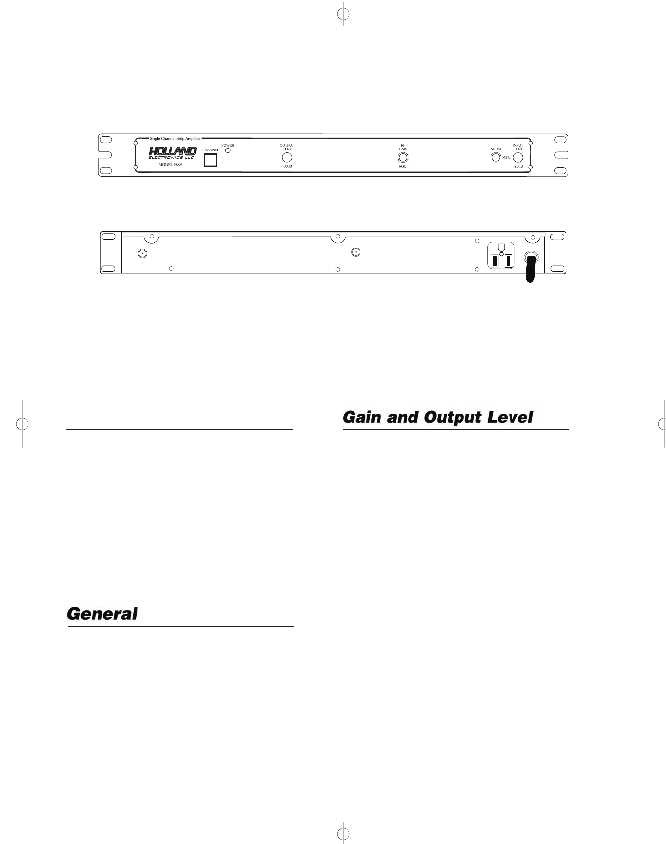
Front View
Single Channel Strip Amplifiers
+
RF IN
+
Bandwidth
HSA: 6 MHz
In-Band Flatness: ± 0.5 dB
Skirt Selectivity
HSA:
Adjacent Channel F0 ±9 MHz: -35 dB
Alternate Channel: -60 dB
UBS:
±3 Channels: -50 dB
±6 Channels: -65 dB
+
OUT
+
+
+
Rear View
FM Band Gain: 55 dB below AGC
Maximum Output
@ (.5 dB sync compression): 66 dBmV
Controls
AGC Stiffness: (30 dB input change)
AGC Range: 4 to 40 dB
Sound Trap: 0 to -10 dB (adjustable)
Front Panel AGC Adjust Range:15 dB
Test Points: Input: -20 dB
Output: -30 dB
±1 dB at output
600 VA MAX
120VAC
60Hz 10W
+
Input Return Loss: -10 dB
Output Return Loss: -15 dB
Power Input: 108 to 125 VAC, 60 Hz, 10 W
Mounting: 19˝ single rack space
Line Cord: 3-wire grounded
3-wire convenience outlet
Operating Temperature: -10° to 50° C
Dimensions: 19˝(L) x 3˝(D) x 1
3
/4˝(H)
Weight: 3.8 lbs.
Ph: 800-421-6511
Note: All specifications are typical
www.picomacom.com
5
Rev. 06/03
Page 3

1
Rev. 06/03
Operation and Controls
1. Channel Identifier:
Indicates the channel for which the unit has been preset.
2. Power Indicator:
Indicates power is on when lit.
3. Output Test:
A -30 dB output test port is provided for ease of system alignment.
4. RF Gain, AGC:
The RF output level and the AGC threshold are controlled from this
potentiometer.
5. Aural Level:
This tunable notch filter allows adjustment of the audio
carrier level.
6. Input Test:
A -20 dB input test point is provided to monitor the incoming signal level.
Front Panel Control
1. IN:
The signal originating from a broadband or yagi antenna is connected at this F connector.
2. OUT:
The filter amplified signal is directly available at this F connector.
3. Convenience Outlet:
This outlet is provided to allow the chaining of amplifiers in the headend equipment rack. The polarized AC outlet is capable of delivering up
to 250 watts of AC power.
4. Power Cord:
This three prong polarized power cord is approved by both UL and
CSA for safe operation of the amplifier. Do not cut the ground terminal for both safety and operational reasons. Connect to 108 to 125
VAC, 50/60 Hz electrical outlet.
Back Panel Control
1
2
3
4
1
2
3
4
5 6
+
RF IN
PAL -*
+
+
OUT
+
+
+
600 VA MAX
120VAC
60Hz 10W
+
Page 4

Rev. 06/03
Installation
It is recommended that assistance be available to safely install equipment in equipment racks.
1. Install chassis in equipment rack (equipment rack sold separately) by supporting the bottom and rear of HSA at the desired elevation
in rack.
2 Line up the side holes of chassis with the tapped equipment rack holes.
3. Insert the provided screws through the side holes in chassis and thread into the tapped equipment rack holes.
4. Fasten the bottom screws first, then fasten top screws (tighten securely).
5. Connect a cable from the source RF signal (single channel antenna or band pass filter) to the input connector of the
6. Connect a cable from the RF output connector to the input connector of the channel combining system.
7. Connect power cord to receptacle supplying uninterrupted line power (LED on front panel will illuminate).
8. Connect a spectrum analyzer or signal level meter to a common channel point of the combining system.
9. Measure nearest adjacent channels amplitude level.
10. Adjust the RF GAIN AGC control on the front panel of the
HSA until channel carrier level is the same amplitude.
HSA.
Warranty
LIMITED WARRANTY Holland Electronics LLC, warrants that the product enclosed with this Limited Warranty statement will conform
to the manufacturer’s specifications and be free of defects in the workmanship and material for a period of five years (5) from the date
of original purchase.
WARRANTY PROCEDURE:
If the product appears to be defective contact Holland Electronics LLC. at (805) 339-9060. We will analyze the problem and offer
solutions to prevent removing the unit from service. If the unit is to be returned for evaluation, you will be issued a Return Material
Authorization (RMA) number. Holland Electronics LLC will, at its option, repair or replace the defective unit, under warranty, without
charge for parts or labor. This repair will be subject to charges if signs of tampering or misuse are detected. Incoming shipping costs
will be the customers responsibility. Returns will not be accepted without an RMA number. The warranty and remedy provided above
are exclusive and in lieu of all other express warranties and unless stated herein, any statements or representations made by any other
person or firm are void. The duration of any implied warranties of merchantability or fitness for a particular purpose on this product shall
be limited to the duration of the express warranty set fourth above. Except as provided in this written warranty, Holland Electronics LLC
shall not be liable for any loss, inconvenience, or damage, including direct, special, incidental, or consequential damages, resulting from
the use or inability to use this product, whether resulting from breach of warranty or any other legal theory. Some states do not allow
limitations on how long an implied warranty lasts and some states do not allow the exclusion or limitation of incidental or consequential
damages, so the above limitation and exclusion may not apply to you. This warranty gives you specific legal rights, and you may also
have other rights which vary from state to sta
IMPORTANT!! WARNING: Holland Electronics LLC does NOT represent this product to be WATERPROOFED. To reduce risk of
electrical shock, fire hazard, or damage to the unit, do not expose to rain or moisture. CAUTION: To prevent electric shock, do not use
this plug with an extension cord, receptacle or other outlet unless the blades can be fully inserted to prevent blade exposure.
NOTE TO INSTALLER: This reminder calls the system installer’s attention to Article 820-22 of the NEC that provides guidelines for
proper grounding and, in particular, specifies that the cable ground shall be connected to the grounding system of the building,as close
to the point of cable entry as practical.
TO PREVENT FIRE OR ELECTRICAL SHOCK, DO NOT EXPOSE THIS UNIT TO RAIN OR MOISTURE
te. To arrange for Warranty Service: Call Holland Electronics LLC. (805) 339-9060
 Loading...