

Page 1

HMMA
Agile Modulator
The HMMA is a high quality SAW filtered frequency agile
modulator designed to meet high CATV performance
standards. The small sized modulator is 1 inch wide for easy
fit into 1 slot of the HMM Modular System. All channels,
CATV 2-135 and UHF 2-69 are selected with convenient
push-button switches. Low out of band noise levels allow
for use in adjacent channel head-ends. The simple operation
of this agile modulator makes the HMMA an excellent
choice where versatility, performance and small size are
required.
• Output Channels: 2 – 135 CATV, 2 –13 UHF and
14-69 UHF
• SAW Filtered
• 45 dBmV Output Level
• Low Out-of-Band Noise
• Easy to Read LED Channel Display
• Convenient Push Button Design
• Crystal Referenced PLL Tuning
HMMA SPECIFICATIONS
RF Output Channels TV: VHF: 2-13; UHF 14-69
CATV: 2-135
Output Level 45 dBmV max
Output Impedence 75 ohms
Output Range 0 ~ -12 dB (adjustable)
A/V Ratio -10 ~ -30 dB
Frequency Stability ± 5 kHz
Aural Carrier Offset +4.500 ± .005 MHz
Spurious Outputs >-60dB
C/N (In-Channel) >60dB
Output Return Loss 7 dB typ
FCC Offsets +12.5 kHz
VIDEO
Input Level 1 Vp-p typ @mod:87.5%
Input Impedance 75 ohms
Input Level Range 0.5 ~ 1.5 Vp-p
AUDIO:
Input Level 0.5 Vp-p typ @ dev: ± 25 kHz
Input Impedance 5K ohms
Input Level Range 0.3 ~ 1.0 Vp-p
Pre-Emphasis 75 us
Installation Instructions:
1. Slide the model HMMA unit into the HMR rack.
2. Power up modulator by connecting the power from the HMPS power supply to the rear of
HMMA.
3. Connect a spectrum analyzer or field strength meter to the modulator RF OUT port.
4. Set the HMMA to the proper channel.
5. Turn the RF output adjustment on the front of the modulator to get desired output level.
6. Turn the A/V adjustment to set the audio carrier 12 to 17 dB below the video carrier
7. Remove analyzer or field strength meter from the modulator RF OUT port
8. Connect baseband audio and video signals to the AUDIO IN and VIDEO IN ports
respectively.
9. Connect modulator RF output to television/monitor. (Make sure to use the proper size
attenuator between the modulator and television so as not to overdrive the television)
10. Turn on television and set to modulator channel
11. Turn the AUDIO adjustment on the front of the modulator to set the sound on television
equal in volume to an off-air channel
12. Turn the VIDEO adjustment to set the video modulation:
Over-modulation causes buzzing sounds, overly bright scenes, and distorted pictures.
Under-modulation results in pictures with dull white levels and dark colors.
13. Remove television/monitor and attenuator from the modulator RF OUT port
14. Connect modulator RF OUT port to the RF input of the head-end system.
Page 2
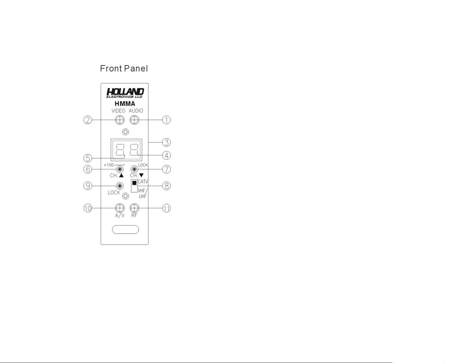
HMMA FRONT PANEL FUNCTIONS
HMMA FRONT PANEL
Functions on Front Panel:
1. AUDIO TRIMPOT:
Adjustment for audio deviation of sound carrier
2, VIDEO:
Adjustment for video modulation percentage of picture carrier.
3. CHANNEL DISPLAY:
Display of output channel number
4. LOCK Indicator
This indicator turns on when the unit is in LOCK mode.
5. +100 Indicator
This indicator turns on when the channel number is 1XX
Example: CH 115 shown as 1.5
6. CH KEY:
Move the channel number upward for output channel selection.
7. CH KEY:
Move the channel number downward for output channel selection.
8. CATV/TV Switch
1. When an output channel required is a terrestrial TV Channel, set the switch to TV
2. When an output channel required is a cable TV Channel, set the switch to CATV
9. LOCK Key
Press LOCK Key to lock up the settings to prevent changing of the output
channel involuntarily.
The LOCK indicator is lit up to indicate that the unit is in LOCK mode.
The CATV/TV Switch and CH /CH Keys are not functional in LOCK
mode.
Press LOCK Key again to exit the LOCK mode. The LOCK indicator
turns off.
10. A/V Adjustment
Adjust for the ratio of picture carrier and sound carrier
11. RF Adjustment
Adjust for the level of output Channel.
 Loading...