

Page 1
INSTALLATION MANUAL
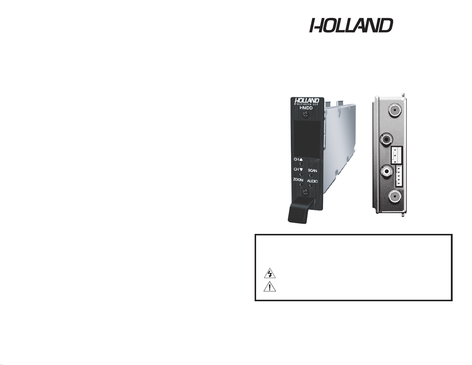
Model:HMDD
ATSC Digital Mini Demodulator
Caution:
These servicing instructions are for use by qualified service personnel only.
To reduce the risks of electric shock, do not perform any servicing other than
that contained in the operating instructions unless you are qualified to do so.
This symbol indicates “dangerous voltage”-there is the risk of an electric shock.
This symbol indicates that there are some important instrutions for this particular
product.
TO REDUCE THE RISK OF ELECTRIC SHOCK, DO NOT TAKE THE COVER OFF.
NO PART OF THE RECEIVER CAN BE REPAIRED BY THE USER.
PLEASE CONSULT A QUALIFIED TECHNICIAN FOR ANY REPAIRS.
WARING:
Electronics LLC
8. TROUBLESHOOTING
a. Ensure you are using quality multiple shielded cables with quality radial or
compression F-connectors.
b. Ensure the cables center conductors are making solid contact with the HMDD
Antenna Input, Audio Output, and Video Output port.
c. If HMDD is receiving power but no signal, check to be sure the video cable is
securely connected between the HMDD and the video source, and the video
and/or audio cables are securely connected between the HMDD and the modulator.
d. If the HMDD is not receiving power make sure the power cable is firmly
connected. Be sure the power source is properly rated to handle the HMDD load
especially if other equipment is being powered by that same source.
-7-
a1.1
Page 2

This package contains:
- One HMDD ATSC Mini Demodulator
- One HMDD Installation Manual
2. PRODUCT DESCRIPTION
The HMDD is an ATSC professional grade mini demodulator designed
for cost effective digital-to-analog conversion of an unencrypted 8VSB (Off-Air
SD/HD TV signal) signal to baseband.
NTSC video and left and right stereo audio outputs. All of the 18 ATSC video
formats including HD format can be received by the HMDD and converted to
display on non-digital TV sets over analog channels with the use of a modulator.
1. PACKAGE CONTENTS
-1-
1
Input frequency range
57-803MHz
2 Channels
2-13(VHF)14-69(UHF)
3
8VSB input channel bandwidth
RF
6 MHz
4
Data rate
19.392 Mbps
In
put level range
-7 dBm to -80 dBm
7 A
djacent channel rejection
60dB
Im
age
rejection
40dB
9
Demodulation m
ode
8VSB, 8VSB MP
10
S
ymbol clock fr
equen
cy
10.762 MHz
11
I
nput connector
75 ohm F-female
GENERAL
1. Video output (analog)
Frequency response
30Hz to 4.2MHz, +/-1.5dB
Video output level
1Vp-p +/- 0.2V
Impedance
75ohms
Connector type
75ohm F-female
2. Audio L/R outputs
Impedance
10K ohms.
Level
1.3Vp-p +/-0.2V
Frequency response
30Hz to 20kHz, +/-2dB
Distortion
1% max
Connector
RCA.
3. Power consumption
Power
DC5V / 350 m A 1.75W
DC12V / 250 mA 3 W
235 x 27 x 88mm
5
Noise figure < 8dB
6
8
3. SPECIFICATIONS
1
[ Air ]
2
3
[ Search ]
4
[ Nosig ]
5
[ A69.1 ]
6
-6-
Press SCAN button for at least 10 seconds to reset to facory default.
CH- button to increase or decrease
volume . (Preset audio volume level of 75%, sample 12)
h.Press and hold ZOOM button, select CH+ to display current signal strength.
(sample 13)
i. Press and hold ZOOM button, select CH- to display current signal quality.
(sample 8 )
j.
7
8
9
[
Language1
]
10
[ Default ]
11
[ Default
Ok ]
12
[ Volume
75% ]
13
14
[ Strengh
96 % ]
[ Quality
100 % ]
g.Press and hold AUDIO button, select CH+ or
k.Fourteen samples of “8” shape display as below:
15
[ 4:3 /
Letterbox]
16
[ 4:3 /
Zoom]
17
[ 4:3 /
Center]
[ 4:3 /
Full]
[ 16:9 /
Zoom]
[ 16:9 /
Center]
[ 16:9 /
LetterBox]
Page 3

4. INSTALLATION AND OPERATION
NOTE TO SYSTEM INSTALLER
System installer must adhere to Article 820-40 of the NEC that provides guidelines
for proper grounding and specifies that the cable ground shall be connected to the
grounding system of the building, as close to the point of cable entry as practical.
1.UNPACKING and HANDLING
Each unit is shipped assembled and factory tested.
Ensure that all accessories are removed from the container before discarding
packing material
2.MECHANICAL INSPECTION
Inspect the front and rear of the equipment for shipping damage. Make sure the
equipment is clean, and no connectors are broken, damaged, or loose.
3.THE USE OF RACK MOUNTABLE CHASSIS AND POWER SUPPLIES
The HMDD is designed to be mounted in a rack chassis designed for mini
modulators, and powered by power supplies intended for mini demodulators and
designed to fit in the mini demodulator rack chassis. The HMR 12-unit rack chassis,and
supply can void the warranty. Up to 11 HMDDs can be configured into a single
HOLLAND HMR with the chassis stabilizer bar in place. Up to 12 HMDDs can be installed
into a single HOLLAND HMR with the chassis stabilizer bar removed.
Note: Using the wrong power supply harness and/or power supply can damage
the HMDD.
Always allow for adequate ventilation when assembling a headend rack.
-2-
the HMPS 12-unit power supply should be used with the HMDD. Use of another power
7. SETTINGS
a. Confirm the HMDD is powered on.
b. Press the HMDD SCAN button. The HMDD will initiate a channel scan for
available ATSC signals/channels in the given area. “SEARCH” will appear in the
HMDD Display. The scan process can take several minutes. You should know
what channels are available in that area, so you can determine which of those
signals needs to be converted and demodulated.
find the one to be converted and demodulated. The HMDD Lock LED will glow
use the CH+ and CH- Buttons to scroll through the available channels until you
shown on the HMDD Display. The HMDD may have find multiple channels,
indicating a channel has been found and selected.
c. When the channel scan is complete, the first found channel number will be
d. Press the “ZOOM” button, you can select up to seven screen types: 4:3 / Center,
allows the selected channel image to be displayed as FULL (full screen display)
or LETTER (letter box with smaller image surrounded by a black border) and center.
4:3 is for standard screen display 16:9 is for widescreen display. The Zoom feature
e.The HMDD provides available language selections . Then, the available language
depends on what stream contains.
(
Not every stream has multi-language selections.
Some have 2 or more language selections , but most streams have 1 language.)
-5-
4:3 / Full, 4:3 / Letter, 4:3 / Zoom, 16:9 / Center, 16:9 / Letter, 16:9 / Zoom
Page 4

5. PRODUCT DIAGRAM
1 Audio Left & Right Output,
RCA connector
2 Video Output , F connector
3 Service connector
4 Power connector
5 Off-air antenna input,
F connector
1 Message and Channel Display
3 CH+ Button search channel up
4 CH- Button search channel down
5 Zoom button select screen format 4:3/16:9
letterbox, full, zoom or center.
7 SCAN Button searches for off-air ATSC signals
8 Audio button selects Audio Language (SAP)
2 LOCK LED indicate signal/channel locked
6 IR receiver (Not Functional)
REAR PANEL
FRONT PANEL
-3-
6. HARDWARE CONNECTIONS
a. The HMDD is designed for installation in a chassis designed for mini demodulators.
Mini demodulator chassis such as the HOLLAND HMR can be mounted in
b. The HOLLAND HMR 12-unit rack chassis and HOLLAND HMPS power supply should
standard 19” EIA racks.
be used with the HMDD. Up to 11 HMDDs can be configured into a HOLLAND
HMR with the HOLLAND HMR stabilizer bar in place or 12 HMDDs
with the stabilizer bar removed.
c. When configuring the HMDD in the chassis with the power supply it is critical that
the power harness being used is from the same vendor as the power supply,
and is designed for that specific supply. Power supply harnesses among
vendors are not interchangeable and can severely damage the HMDD.
d. The use of a surge protector and a UPS is highly recommended.
Product warranty does not cover surge or spike damages.
e. Connect a 75-ohm coaxial cable with proper connectors from the HMDD
Antenna Input Port to an Off-Air antenna .
f. For mono audio output connect an audio patch cable with RCA male
connectors on both ends between the HMDD Audio LEFT (White) output port
to the modulator’s audio input. For output to a stereo modulator use patch cables
from the HMDD Audio LEFT (White) and RIGHT (Red) output ports.
g. Connect a coaxial cable using a male F-connector to the HMDD Video
Output and a male F-connector to the modulator’s video input
h. Note you will require 1 HMDD for each channel or subcarrier to be converted
and demodulated. You will also require 1 modulator for each channel to be
remodulated.
i. Connect the HMDD to the power harness and power supply installed in the
mini demodulator chassis.
-4-
 Loading...