

Page 1
INSTALLATION MANUAL
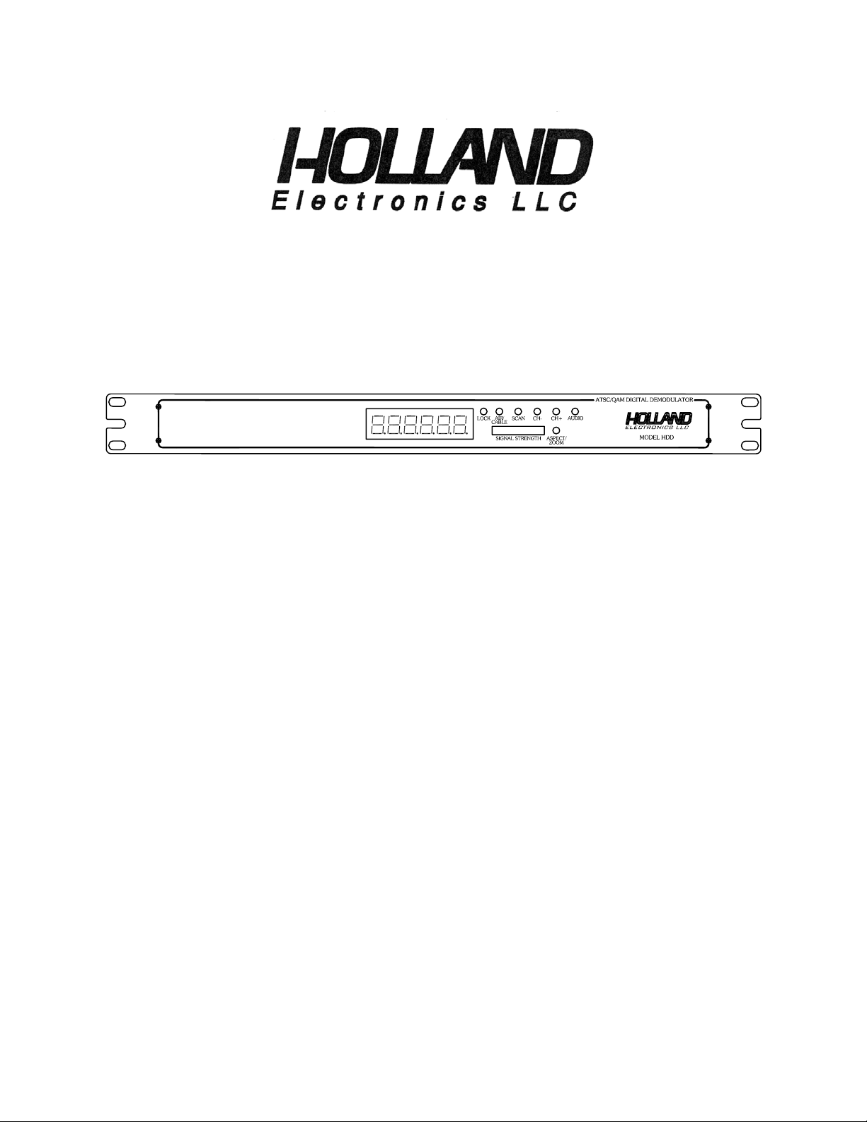
Model :HDD
ATSC/QAM Digital Demodulator
1
Page 2

PACKAGE CONTENTS
This package contains:
One HDD ATSC/QAM Demodulator
One HDD Installation Manual
PRODUCT DESCRIPTION
The HDD is an ATSC/QAM professional grade demodulator designed for cost effective
digital-to-analog conversion of an unencrypted 8VSB (Off-Air SD/HD TV signal) or QAM
unencrypted (digital CATV) RF signal to baseband NTSC video and left and right stereo audio
outputs. All of the 18 ATSC video formats including HD format can be received by the HDD and
then converted for display on non-digital TV sets over analog channels with the use of a
modulator.
SPECIFICATIONS
RF
1. Input frequency range 54 – 860MHz
2. Channels 2-13 (VHF) 14-69 (UHF)
3. 8VSB input channel bandwidth 6 MHz
4. Data rate 19.392 Mbps.
5. Noise figure < 8dB
6. QAM input frequency range CATV 2-135
7. QAM data rate 27 Mbps
8. QAM 256 data rate 38 Mbps
9. Input level range -7 dBm to -80 dBm
10. Adjacent channel rejection 60dB
11. Image rejection 40dB
12. Demodulation mode 8VSB, 8VSB MP @ ML
13. Symbol clock frequency 10.762 MHz
14. Input connector 75 ohm F-female
GENERAL
1. Video output (analog)
Frequency response 30Hz to 4.2MHz, +/-1.5dB
Video output level 1 Vp-p +/- 0.2Vp-p
Impedance 75ohms
Connector type RCA
2. Audio L/R outputs
Impedance 600 ohms.
Level 1 Vp-p +/- 0.2Vp-p
Frequency response 30Hz to 20kHz, +/-2dB
Distortion 1% max
Connector RCA
3. Power
Power 8.33W / AC120V / 60Hz
Voltage Range AC100V ~ AC120V /57Hz ~ 63Hz
Dimensions : 483 x 86 x 44mm
2
Page 3

INSTALLATION AND OPERATION
1. UNPACKING and HANDLING
Each unit is shipped assembled and factory tested.
Ensure that all accessories are removed from the container before discarding packing material
2. MECHANICAL INSPECTION
Inspect the front and rear of the equipment for shipping damage. Make sure the equipment is
clean, and no connectors are broken, damaged, or loose.
3. THE USE OF RACK MOUNT UNITS AND POWER REQUIREMENTS
The HDD is designed to be mounted in standard 19” EIA racks and to be powered by
AC110V/60Hz power. Using the wrong AC power voltage can damage the HDD.
Contact your distributor for more information.
3
Page 4

4. PRODUCT CONTROLS and CONNECTIONS
REAR PANEL
1 Antenna Input for Off-Air or CATV (F connector)
2 Video Output (RCA connector)
3 Audio Left Output (RCA connector)
4 Audio Right Output (RCA connector)
5 RS-232 Input (For Future Use)
6 AC Power Cord AC120V / 60Hz
7
AC Power Socket for Extension
FRONT PANEL
1 Message and Channel Display
2 Signal Strength Indicator
3 CH+ Channel up button
4 CH- Channel down button
5 Scan button (searches for digital RF input signals)
6 AIR/CABLE button selects OFF-AIR (8VSB) or CABLE (QAM)
7 LOCK LED indicate signal/channel locked
8 Aspect/Zoom button (user selectable screen format for 4:3/16:9 letterbox, full, zoom, or center)
9 Audio button (select between English and SAP)
4
Page 5

5. HARDWARE CONNECTIONS
a. The HDD is designed for installation in a standard 19” EIA racks.
b. The use of a surge protector and a UPS is highly recommended. Product warranty does not
cover surge or spike damages.
c. Connect a 75-ohm coaxial cable with proper connectors from the HDD Antenna Input Port to
the Off-Air antenna or other cable source.
d. For mono audio output connect an audio patch cable with RCA male connectors on both e nds
between the HDD Audio LEFT (White) output port to the modulator’s audio input port. For
output to a stereo modulator use patch cables from the HDD Audio LEFT (White) and Audio
RIGHT (Red) Output ports.
e. Connect a coaxial cable using an RCA male connector to the HDD Video Output Port
and a male F-connector to the modulator’s video input port.
f. Note you will require 1 HDD for each channel or subcarrier to be converted and demodulated.
You will also require 1 modulator for each channel to be remodulated.
g. Connect the HDD to the AC power.
5
Page 6

6. SETTINGS
a. Confirm the HDD is powered on and the input signal cable is connected to the antenna input
port on the rear of the HDD.
b. Select input signal type, Off-Air (8VSB) or Cable (QAM) using the HDD Air/Cable
Selection Button.
c. Press the HDD Scan button. The HDD will initiate a channel scan for available
signals/channels in the given area. “SEARCH” will appear in the HDD Display. The scan proce ss
can take several minutes. Based on knowing what channels are available in the area you can
determine which of the signals needs to be converted and demodulated.
d. When the channel scan is complete one of the found channels numbers will be shown in the
HDD Display. The HDD may find multiple channels. Use the CH+ and CH- Buttons to scroll
through the available channels until you find the desired channel to be converted and
demodulated. The HDD Lock LED will light up indicating a channel has been found and selected.
e. The desired channel should have sufficient signal strength to produce a quality image. Use the
HDD Signal Strength Meter. Each segment on the meter represents 15% signal strength rangin g
from 15% or less for the bottom (red) bar up to 90% or greater for the top and last bar.
f. The HDD includes an alternate Audio function (SAP) which allows the user to select from
English or Spanish audio content (if available). To select English audio press the Audio button on
the HDD until the display reads Lang1. To select Spanish audio press the Audio button on the
HDD until the display reads Lang2.
Note: Some broadcasters do not default the SAP audio back to English audio if the program being
broadcast does not support SAP. When a program does not support SAP but the HDD is set to
Lang2, there will be no audio outputted of the HDD. This is a function of the broadcasters
transmission and in no way means the HDD is defective.
g. The HDD also includes a Aspect/Zoom feature that allows the selected channel picture to be
displayed either as 4:3 Full, Letterbox, Center, and Zoom for standard screen display or 16:9
Letterbox, Center, and Zoom for widescreen display. You may use the HDD Aspect/Zoom
Button to select the desired screen format to be displayed on the television. However, the Zoom
feature is channel dependent. Further, as the Zoom setting could be considered a viewer
preference it may be advisable leave the setting in the default position. Note: The available aspect
ratio may be channel and program dependent making selection impossible. Selected aspect ratio
and format will be shown on the HDD Display.
.
h. Six samples of “8” format display as below:
1. [ Air ] 2. [Cable] .
90 75 60 45 30 15 % Signal strength
3. [ Search] 4. [NoSig]
5. [ A 69.1] 6. [130.556]
6
Page 7

7. TROUBLESHOOTING
a. Ensure you are using quality multiple shielded cables to prevent signal ingress.
b. Ensure the cables center conductors are making solid contact with the HDD Antenna Input,
Audio Output, and Video Output port.
c. If the HDD is receiving power but no signal, make sure the video cable is securely connected
between the HDD and the video source, and the video and/or audio cables a re securely
connected between the HDD and the modulator.
d. If the HDD is not receiving power make sure the power cable is firmly connected. Be sure the
power source is properly rated to handle the HDD load especially if other equipment is being
powered by that same source.
Caution: These servicing instructions are for use by qualified service person nel only. To reduce
the risks of electric shock, do not perform any servicing other than that contained in the operating
instructions unless you are qualified to do so.
7
Page 8

HOLLAND ELECTRONICS LLC
LIMITED WARRANTY
Holland ELECTRONICS LLC, warrants that the product enclosed with this Limited Warranty
statement will conform to the manufacturer’s specifications and be free of defects in the
workmanship and material for a period of five years (5) from the date of original purchase.
WARRANTY PROCEDURE:
If the product appears to be defective, contact Holland Electronics LLC at (805) 339-9060. We
will analyze the problem and offer solutions to prevent removing the unit from service. If the unit
is to be returned for evaluation, you will be issued a Return Material Authorization (RMA) number.
Holland Electronics LLC will, at its option, repair or replace the defective unit, under warranty,
without charge for parts or labor. This repair will be subject to charges if signs of tampering or
misuse are detected. Incoming shipping costs will be the customer’s responsibility. Returns will
not be accepted without an RMA number.
The warranty and remedy provided above are exclusive and in lieu of all other express warranties
and unless stated herein, any statements or representations made by any other person or firm are
void. The duration of any implied warranties of merchantability or fitness for a particular purpose
on this product shall be limited to the duration of the express warranty set fourth above. Except as
provided in this written warranty, Holland Electronics LLC shall not be liable for any loss,
inconvenience, or damage, including direct, special, incidental, or consequential damage s,
resulting from the use or inability to use this product, whether resulting from breach of warranty or
any other legal theory.
Some states do not allow limitations on how long an implied warranty last s and some st ates do not
allow the exclusion or limitation of incidental or consequential damages, so the above limitation
and exclusion may not apply to you.
This warranty gives you specific legal rights, and you may also have other rights which vary from
state to state.
To arrange for Warranty Service: Call Holland Electronics LLC (805) 339-9060
8
 Loading...