

Page 1

DST-5000/DSTR-5000
DARK SYSTEM TE STER
Page 2

Table of Contents
Features / Specifications…………………… …...… ….………… . 1
Keypad Illustration
Key Function Description……………….………….…………….. 3
Getting Started Tips:
Powering the Transmitter & Receiver……………………... 5
1.
Adjusting the Transmitter Carrier Power Levels……….. 5
2.
Main User Instructions:
Operating Modes
1 Turning Power On……………..…………………………….….…. 6
2 REC Mode………………………………………… .………… .…… .. 6
3 Cable ID Mode
4 TDR Mode………..…………………………………….…… ..…….. 9
5 Auto Shut Down Selection……………………..………………. 11
Appendix A:
Appendix B:
RS-232 Cable Pin-Out Details…………………………. 28
Rev B
6 Downloading Data to a Remote PC via RS-232 11
7 Charging Batteries………………………………… ……………. . 12
Warranty…………………………………………………..……….. .… 14
Configuring the RS-232 Port on a Remote PC……... 15
………… . . . …………………………..…… …… 3
……………………… …………….……..… ……… .. 8
Page 3

FEATURES
* TDR Feature to ID Cable Faults (Open & Short) * RS-232 Data Downloading Port
* Signal Level Loss tested @ 5 frequencies * Auto Shutoff Power Saving Feature
* Cable ID Function * 8 HR Re chargeable Li-On Batt eries
* 50 Memory Stations
DARK METER RECEIVER (Model # DST-5000) SPECIFICATIONS
Input :
Input Impedance 75 ohm
Input Frequency Cable Mode : 20, 55.25, 950, 1450, 2150MHz
Input Level Range Cable Mode : +23dBmV ~ -16dBmV @ 20, 55.25, 950, 1450, 2150MHz
Connector F male
LCD Di splay:
Display type STN, B/W, DOT Matrix 64 128
View area 70 40mm
Measurement Range:
Level measur ement: Cab l e Mod e : 0 ~ 40dB @ 20, 55.25MHz
0 ~ 40dB @ 950, 1450, 2150MHz
Full display level: 40dB total in 20 Bar steps @ 2db
Level per step: 2dB per step
Store Stations 50 Station
Cable ID: 1 ~ 20 ID tags
@ Tagging resistor range 1.0K ohm to 20.99K ohm
@ Nominal tag value1: 1.0 …….1. 99K ohm
2 : 2.0 ……..2.99K ohm
20 : 20.0……20.99K ohm
@ SHORT 220 ohm
@ OPEN 21K ohm
TDR :
Test cable RG58, RG59, RG6, RG11
Impedance 50 or 75 ohms
Measure cable lengths 300 ft Max./ 15ft Min.
Accuracy +/- 3.5ft @ 20ft, +/- 6.0ft @ 200ft and +/- 3% @ 300ft
Power Req uired:
Battery, Rechargeable Li- Ion, 7.4VDC @1600mAH
AC Line Voltage 100-240V 50/60Hz
Charge Time 5 HRS typ. w/Built-in Charger
DC Adapter 9 VDC @800mA
PC Interface:
RS232 Use with WINDOWS SMART TERMINAL
RS232 Connector DB9
Mechanical:
Dimensions (W H D) 104 47 234mm
Weight 500g
STANDARD ACCESORIES
Battery Charger: 1 pc Carrying Case w/strap: 1 set
Barrel Connector: G-F81F* 2 pcs Operators Manual: 1 copy
RS-232 Data Transfer Cable 1 pc
Electronic copie s of the Users Manual are available on our website:
www.hollandelectronics.com/support.html
1
Page 4

DARK METER TRANSMITER (Model # DSTR-5000) SPECIFICATIONS
Output :
Output Impedance 75 ohm
Output Frequency Cable Mode : 20, 55.25, 950, 1450, 2150MHz
Output Level Range Cable Mode : +20dBmV max @ 20, 55.25, 950, 1450, 2150MHz
Output Control Range 5 ~ 10db
Connector F male
Power Req uired :
Battery, Rechargeable Li- Ion, 7.4VDC @ 1600mAH
AC Line Voltage 110-240V 50/60Hz
Charge Time 5 HRS typ. w/Built-in Charger
DC Adapter 15VDC @ 800mA
Mechanical :
Dimensions (W H D) 87 40 130 mm
Weight 335 g
STANDARD ACCESORIES
Battery Charger: 1 pc
Carrying Case w/strap 1 set
Barrel Connector 2 pcs
2
Page 5
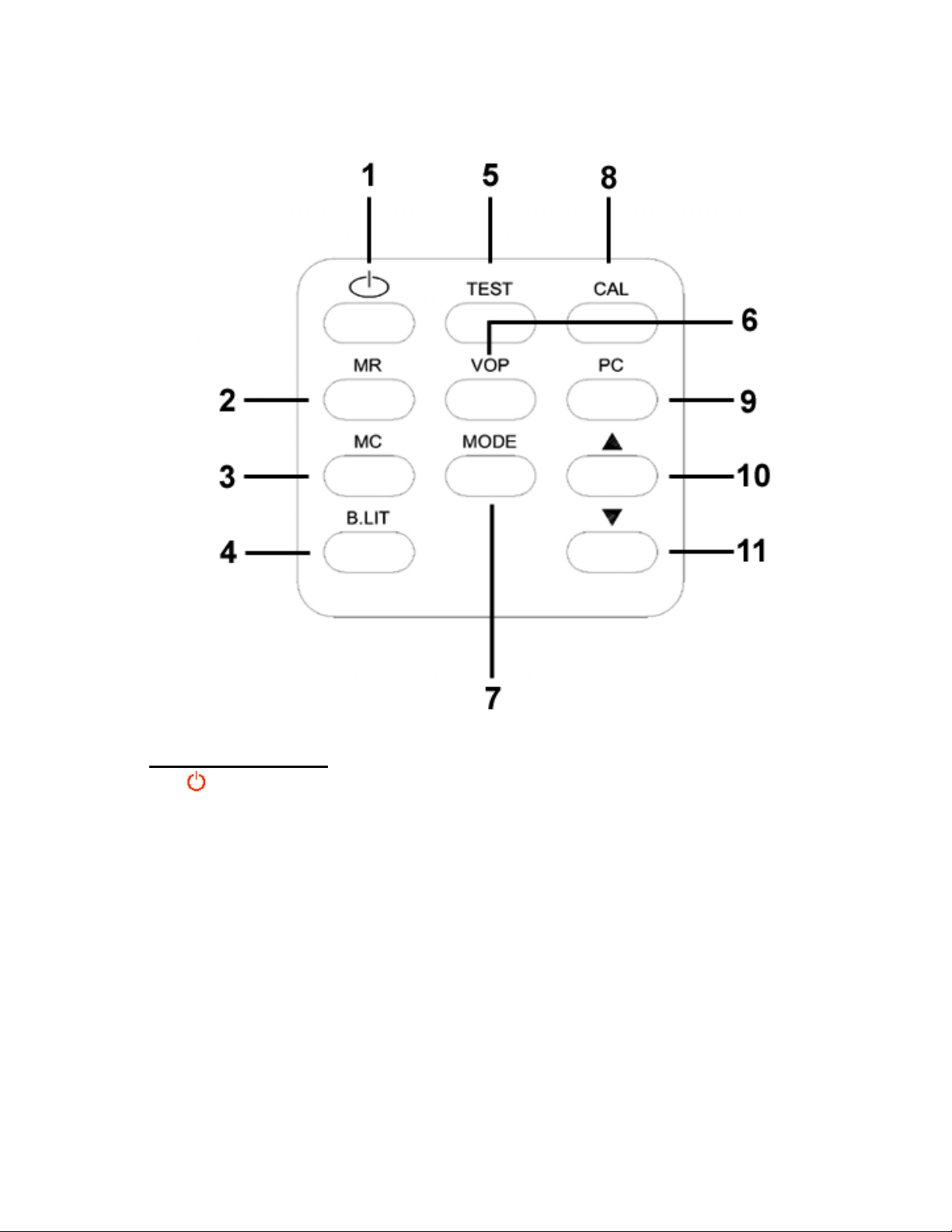
KEYPAD ILLUSTRATION
Key Functions :
1. Key :Power Key
ON/OFF
2. MR Key :Store Key
Press to store data in memory
3. MC Key :Clear Key
This key serves two functions while the meter is in the REC mode :
3.1 P ress MC Key for 2 seconds :
Erase the current station mem ory.
3.2 P ressMC Key and the STKey) for 5 seconds :
Erase all station memories.
4. B. LIT Key :
Press to turn On/Off the LCD display back lighting.
3
Page 6

5. TEST Key:
Press this key in the TDR mode and measure a distance to a cable fault
6. VOP Key:
Toggle the VOP Key to select from the preprogrammed VOP values for
different cable types.
7. MODE Key :
This key allows the user to select measurement & setup modes:
7.1 Push the MODE Key to select REC mode :
Measure 5 carrier signal levels from the Dark Transmitter.
7.2 Push the MODE Key again to select CABLE ID mode :
Tags an ID number to a cable that matches the resistor value terminated
at the cable end or displa ys OPEN or SHORT if either conditi on exists.
7.3 Push the MODE Key again to select TDR mode :
Measures distance to a cable fault (open/short), using TDR technology
7.4 Push the MODE key again to select Auto Shutdown Mode and then
select the inactivity period before the meter automatically shuts down.
8. CAL Key :
This key activates 2 functions:
8.1 Press the CAL Key in REC mode :
This is to store the input signal level as a calibrating reference level.
8.2 Press the CAL Key in TDR mode :
This is to store the VOP value calculated from a 20 ft cable as a
calibrat ing refer ence VOP value.
9. PC Key :
Press to download saved signal level data via the RS232 port to a PC
10/11. / Keys :
Use to select memory stations
4
Page 7

Getting Started
_____________________________________________________________________
Powering the Dark System Transmitter and Receiver
The transmitter (DSTR-5000) and receiver (DST-5000) are shipped without the
batteries installed. The user should remove the rear cover on each unit and
install the battery packs before proceeding.
Using the external AC power supply: Make sure that the available AC
A)
line voltage is 110-240V, 50/60 Hz. Connect the DC output plugs f rom
each of the ada pter/cha rgers t o the DC recept acles on t he DST and
DSTR units.
B) Powering the transmitter and receiver with internal batteries: In order
for the DST and DSTR t o operate from the internal batteries, a suff icient
charge must exist on the batteries. The recommended time to fully
charge the batteries is 5 hours. The power supply / battery charger
included with the DST-5000 is different than the power supply / battery
charger for the DSTR-5000. DO NOT interchange the chargers. The
batteries will charge whether the units are switched On or Off. When
the charg er for the transmit ter (DSTR) is c onnected to an AC so urce,
the Charge LED will be illuminated Amber during a charging cycle
and Green if charging is complete.
Warning: Only Use The Power Supply / Battery Charger Supplied by Holland
Electronics with The Transmitter (DSTR-5000) and the Receiver (DST-5000).
Do not interchange the charging units between the DST and DSTR units.
Use Of Any Other Chargers Will Void the Warranty and Can Cause
Damage Or Injury.
Adjusting the transmitter carrier output levels
The transmitter carrier power levels should not normally need to be adjusted for
the Dark System to operate properly. Ho wever, the levels can be checked
when the uni t is used for the fir s t time or should the op erator experience trouble
using th e equipment during normal operation.
The transmitter (DSTR-5000) output consists of five different frequency carriers.
The power level of ea ch carrier can be adjusted separately with the
potentiometers mounted on the top of the housing (near the output connector).
The exact output level of each carrier is not extremely critical for nor mal
operati on because the receiver input referenc e levels for each carr ier
frequency are set to match the transmitter levels during a calibration process
the user performs b y connecting the transmitter and receiver to gether pri or to
making signal level measurements (See Section 2.1).
If the user prefers to know the ex act transmitt er output po wer levels then the
transmitter can be directly connected to a spectrum analyzer or a power meter
and each of the carrier levels set to a known value. Always reconnect the
receiver and transmitter together and perform a calibration exercise to reset the
receiver input reference levels (See Section 2.1) after adjusting any of the
transmitter output level potentiometers.
5
Page 8
Operating Modes:
Once the meter power is turned on there are three different o perating modes
and one set-up mode tha t can be selected. Pressing the MODE Key repeatedly
will sequence the receiver through the different modes as described below in
sections 2 - 5.
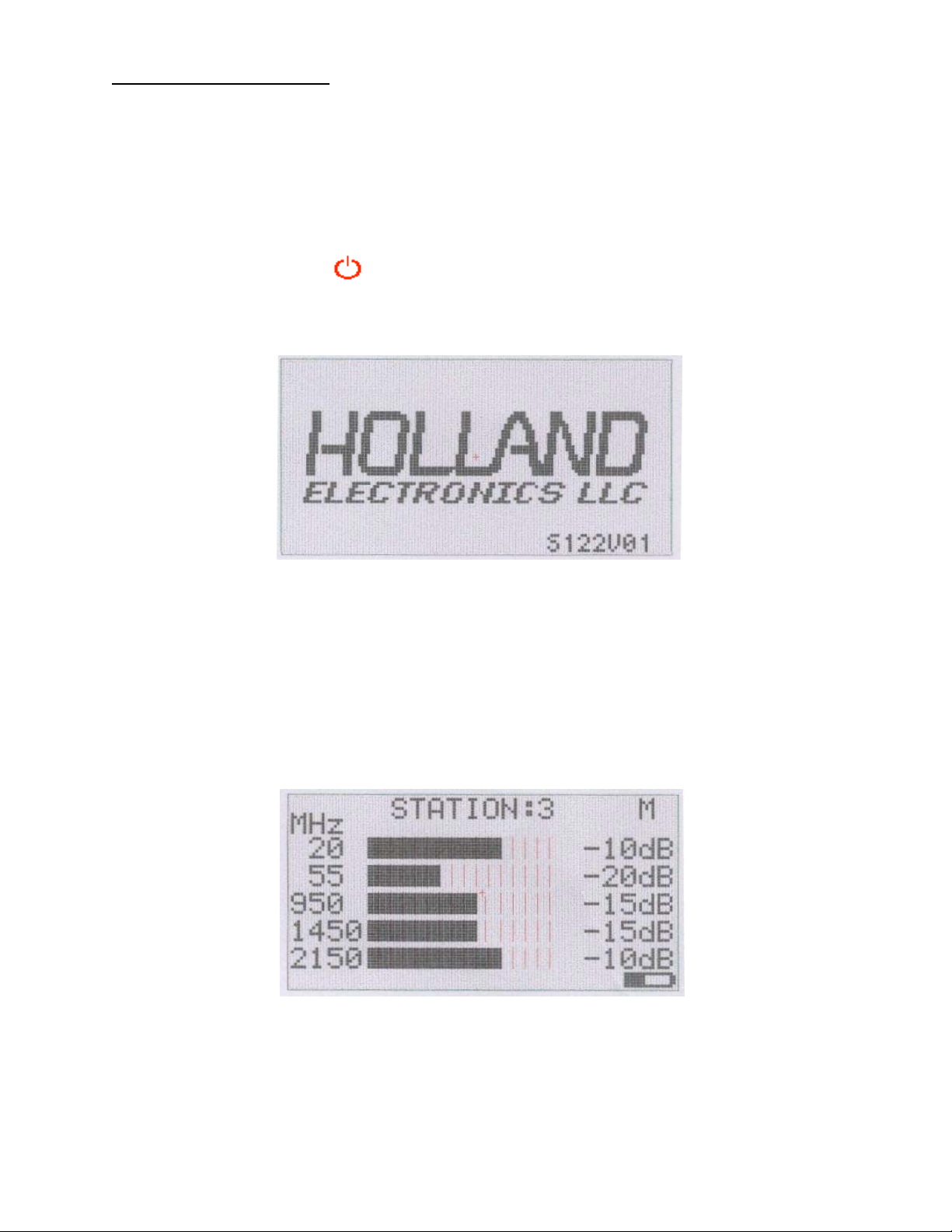
1. POWER ON
Press the Power Key to turn on the receiver. The LCD display will look
similar to the following:
2. REC MODE
In this mode, the amount of inser tion loss between the transmitter and
receiver connected to a cable under test is measured and displayed for fi ve
different frequenci es. These insertion l oss values can also b e stored in
memory and then recalled at a later time for review or downloaded to
another device via the RS-232 port.
• The measurement level is displ ayed over a range of 20 bars, at 2 dB per
bar. When all bars are illumina ted for a given frequency t hen there is less
than 2db of measured signal level insertion loss betw een the tra nsmitter
and receiver.
6
Page 9
2.1 Measuring Insertion Loss:
The Insertion Loss or the Attenuation of the cable under test (CUT) can be
measured as follows:
2.1.1 Connect the transm itter dir ectly to the i nput of the receiver. Use a high
quality splice or a jumper cable that is no more than 1 2 inches between
transmitter and receiver for this step. NOTE: Normally the transmitter
output levels do not require adjustment b efore perfo rming this step unles s
the operat or is experiencing erratic op erati on or measurements
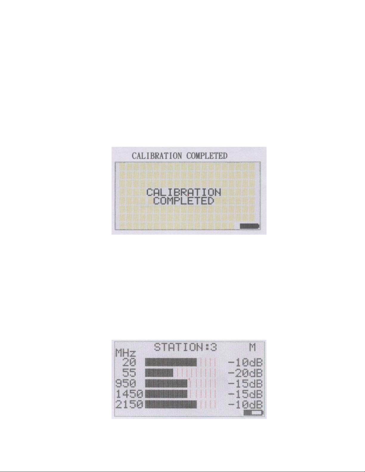
2.1.2 Press th e CAL Key to initiate a calibration operation. The receiver will store
the measured signal levels of each carrier and use them as reference
levels. The LCD display will appear as shown below.
2.1.3 The display will t hen show all five bars fully illuminated across the screen
and –0db noted for each fr equency. If -0db is not displayed for each
value then try adjusting the carrier level potentiometer on the transmitter
for the frequency in question a nd repeat t he calibrat ion procedure.
2.1.4 Disconnect the transmitter fr om the receiver and connect the transmitter
to one side of the CUT and the receiver to the other side. The receiver will
display the a ttenuation values of the CUT. The LCD should look similar to
the following :
7
Page 10

2.1.5 To store the measured values, use the / keys to select a desired
memory station (1-50) on the disp lay. Then press the MR Key for 2 seconds
to stor e the measurement data into the desi gnated station memory
location.
The letter “M” will be displayed in the upper right corner of the screen to
indicate stored values in the desig nated station memory location. Old
data must be cleared from a statio n by pressing and holding the MC Key
for 5 seconds before new measured values can be saved.
The stored data in all fifty memory locations can be cleared in a single
operation by pressing both the MC Key and the STKey for 5 seconds.
3. CABLE ID MODE:
In this mode, the receiver can be used to id entify uni d entifed cables by
attaching specially m arked terminators (Holland p/n PFTK) to one end of
each cable. The meter can read the terminator resistance and display the
specific ID of the terminator corresponding to the chart below:
3.1 Press the MODE key to select Cable ID mode. The LCD will display as shown
Resistan ce ohms Cable ID Display Resistan ce ohms Cable ID Display
0 ~ 210 SHORT 11K ~ 11.99K 11
220 ~ 990 -- -- 12K ~ 12.99K 12
1K ~ 1.99K 1 13K ~ 13.99K 13
2K ~ 2.99K 2 14K ~ 14.99K 14
3K ~ 3.99K 3 15K ~ 15.99K 15
4K ~ 4.99K 4 16K ~ 16.99K 16
5K ~ 5.99K 5 17K ~ 17.99K 17
6K ~ 6.99K 6 18K ~ 18.99K 18
7K ~ 7.99K 7 19K ~ 19.99K 19
8K ~ 8.99K 8 20K ~ 24.5K 20
9K ~ 9.99K 9 24.5K ~ OPEN
10K ~ 10.99K 10
below:
8
Page 11

3.2 Connect the r eceiver to one end of t he CUT and one of the special
terminators to the other end of the CUT. The correspondi ng value of the
terminator will be displayed on the LCD display to identify the cable.
4. TDR Mode :
The TDR mode p rovides a method for determining if the cab le under test has an
open circ uit or a short circuit condi tion an d approximately how f ar down the
cable from the receiver this fault exist s .
The propagation constant (VOP) for standard indust ry cables (RG-6, RG-59,
RG-11, RG-58) i s preprogrammed but the user can also connect a piece of
cable and perform a custom calibration before using the TDR for fault testing.
4.1 Press the MODE Key to select the TDR mode.
Use the following procedure when testing cable wi th a known VOP value:
4.1.1 Press th e VOP Key to select the specific VOP v alue of the cable under test.
4.1.2 Connect o ne end of the CUT to the receiver input connector.
4.1.3 Press th e TEST Key to test & display the type of cable fault (open/short)
and the distance (in feet) to the ca ble fault location.
The LCD will display as shown below:
9
Page 12

4.1.4 To perform testing on other secti ons of cab le with the s ame VOP value,
simply disconnect the CUT, reconnect the meter to another piece of
cable and press the TEST Key again.
4.2 Use the following procedure when testing cable with an unknown VOP value:
4.2.1 Press th e MODE Key to select the TDR mode.
4.2.2 Press th e VOP Key to select “0.XX CAL” on the display.
4.2.3 Connect a 20ft piece of cable with the unknown VOP value to the input
connecto r. Leave th e other end of the cab le open and u n-terminated. It
is important that a 20 ft length of cable be used for this calibration.
4.2.4 Press th e CAL Key to measure and display a calibrated VOP value.
4.2.5 Remove the 20ft cable and connect the actual CUT to the receiver input
connector.
4.2.6 Press th e TEST Key to test a nd display the cable fault (open/short) and the
distance to the fault location.
The LCD will display as shown below:
4.2.7 If the display shows FAULT: XXXX and LENGTH:XXXX this indicates one of
two typical conditions:
• The cable length is too short to prop erly test or the fault is too clo se (<15ft)
to the receiver.
• The cable length under test i s too long (>300ft), or it has very hig h insertion
loss
10
Page 13

4.2.8 To perform testing on other secti ons of cab le with the s ame VOP value,
simply disconnect the CUT, reconnect the meter to another piece of
cable and press the TEST key again.
4.2.9 Press th e MODE Key to select another mode.
5. AUTO SHUT DOWN :
Allows the user the ability to set the amount of time before the meter will shut
off if no keypad activity is sensed.
5.1 Use the MODE key to select the Auto Shut Down Menu.
5.2 Use the / keys to select the duration of time before shut down occurs. The
choices are 2,10, 30 minutes or OFF(the meter will not automatically shut off).
The LCD display will look similar to the following :
5.3 After making the desired selectio n, press the MR Key to store the shutdown
time setting.
5.4 Press the MODE Key to select another mode.
6. DOWNLOADING STORED DATA:
All stored station memory data ca n be transferred from the receiver t o a PC
via the built-in RS232 port.
6.1 In order to transfer the data, the users PC must be configured to operate as a
smart terminal through a RS-232 port. See Appendix A for the necessary steps
to be taken in Window s to enable communicat ions.
6.2 Connect the PC to the receiver using the suppl ied RS-232 cable (see
Appendix B for the proper cable pin-out) to the Receiver and then press the
PC Key to begin the download operation. The LCD will look similar to the
following:
11
Page 14

6.3 Once the receiver has transferred all of the stored data, the LCD display will
resume showing the previous menu screen prior to the downloading
operation.
7. CHARGING BATTERIES:
Receiver
7.1 The receiver (DST) has a battery indicator symbol that is displayed in the
lower r ight corner of the LCD.
7.2 When the displayed battery indicator is simply an empty battery symbol and
it begins flashing then the battery is nearly fully discharged.
7.3
Connect the DC charger adapter supplied with the receiver to a 110-240
VAC source. The LCD display will indicate that charging has begun as
shown below:
7.4 When the battery symbol stops flashing and the LCD display indicates as
shown below then the battery has been fully charged and will typically allow
for 8 hrs of normal operation without the backlight illuminated. With the
backlight illuminated continuously, normal operation time between charges
will be approximately 3 hours.
12
Page 15

NOTE: The DST receiver charging circuit is designed such that the receiver
will automatically be turned on whenever a charging operation is begun.
When the battery charging cycle is completed, the charger will continue
to supply current to operate th e receiver and not drain the battery.
To operate the receiver while the wall charger is plugged in, simply press
the MODE button to select the desired operation.
Transmitter
7.5 The transmitter (DSTR) unit has a red LED that will be illuminated when the unit
is turned on and the battery vol tage drops bel ow a preset level.
7.6 To charge the transmitter, simply connect the DC charger adapter supplied
with the transmitter to a 110 – 240 VAC source. A separate LED will indicate
that charging is in process. While charging this LED will be amber color.
When the charging cycle is completed, th e LED color will change to green.
13
Page 16

HOLLAND ELECTRONICS LLC
LIMITED WARRAN TY
Holland Electronics LLC warrants that the product enclosed with this Limited
Warranty statement will conform to the man ufacturer’s specifications and be free
of defects in the workmanship and material for a period of one-year (1) from the
date of origin al pur cha s e
WARRANTY PROCEDURE:
If the product appears to be defective contact Holland Electronics LLC. We will
analyze the problem and offer solutions to prevent removing the unit from
service. If no solution is found, and the unit must be returned for repair, you will
be issued a Return Authorization (RA) number.
Holland Electronics LLC will, at its option, repair or replace the defective unit
under warranty, without charge for parts or labor. This repair will be subject to
charges if signs of tampering or misuse are detected. Incoming shipping costs
will be the customer’s responsibility. Returns will not be accepted without an RA
number.
The warranty and remedy provided above are exclusive and in lieu of all other
express warranties and unless stated herein, any statements or representations
made by any other person or firm are void. The duration of any implied
warranties of merchantability or fitness for a particular purpose on this product
shall be limited to the duration of the warranty set forth above. Except as
provided in this written warranty, Holland Electronics LLC shall not be liab le for
any loss, inconvenience, damage, including direct, special, incidental, or
consequential damages, resulting from the use or inability to use this product,
whether resulting from breach of warranty or any legal theory.
Some states do not allow limitations on how long an implied warranty lasts and
some states do not allow the exclusion or limitation of incidental or
consequential damages, so the above limitation and exclusion may not apply to
you.
The warranty gives you specific legal rights, and you may also have other rights,
which vary from state to state.
To arrange for warranty service: Call Holland Electronics LLC (805) 339-9060
Return Address with appropriate Return Authorization Number:
2935 Golf Course Drive
Ventura, CA 93003
.
14
Page 17

APPENDIX A
The following screen illustrations will show the user how to configure the Windows
based Hyper Terminal program and RS-232 port on their PC in order to properly
communicate with the Dark System Receiver.
15
Page 18

16
Page 19

17
Page 20

18
Page 21

19
Page 22

20
Page 23

21
Page 24

22
Page 25

23
Page 26

24
Page 27

25
Page 28

26
Page 29

27
Page 30

APPENDIX B
RS-232 Cable Pin-Out Details
The cable is wired with straight pin-pin connections
1-1
2-2
3-3
4-4
5-5
6-6
7-7
8-8
28
 Loading...