

Holland KINGPIN Specifications And Installation Instruction
KINGPIN
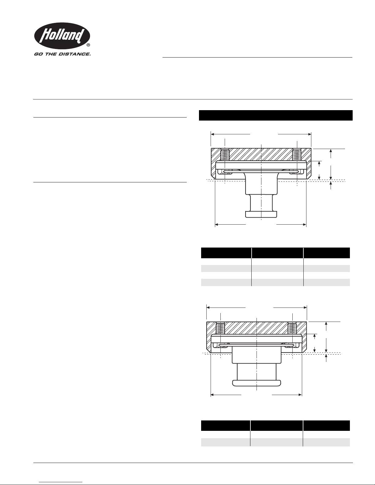
SAE 2.00˝ KING PIN
9.00˝ SQ.
8.25˝ DIA.
2.75˝
A
B
BOLSTER PLATE
2.75˝
A
B
BOLSTER PLATE
SAE 3.50˝ KING PIN
9.00˝ SQ.
8.25˝ DIA.
REPLACEABLE KINGPIN
SPECIFICATIONS and
INSTALLATION INSTRUCTIONS
HOLLAND REPLACEABLE KINGPINS PROVIDE:
Secure installation.
•
• Ease and economy of replacement should wear or
damage occur to the kingpin.
This series of kingpins is designed specifically for van
and enclosed trailers, but can be used on other types of
trailers as well. The kingpin design permits economical
replacement of the kingpin since it is bolted in place —
no expensive rework of the trailer upper coupler.
STANDARD FEATURES INCLUDE:
1. Secure installation with eight .75˝ diameter Grade 8
bolts and safety wire lock.
2. Kingpins are made of AISI 8630H alloy steel and
hardened to 302-363 BHN. When properly installed,
will meet or exceed the performance requirements set
by the Society of Automotive Engineers (SAE) and the
Truck Trailer Manufacturers Association (TTMA).
3. High impact and wear resistance.
4. Housings are made of AISI 4130H alloy steel for
weldability.
5. 100% Brinell hardness tested.
6. 100% magnetic particle tested (to inspect for integrity
below the surface).
7. Ultrasonic tested (MS 105, Tightened, C=0).
8. Bolster plate thicknesses are designed into the
housings as shown. Only one kingpin, either SAE 2˝
or 3.5˝ is required for service parts.
DIMENSIONS
2˝ KINGPIN B A
WITH HOUSING BOLSTER PLATE COUNTER BORE
KP-0880 .25˝ 1.56˝
KP-0881 .31˝ 1.50˝
KP-0882 .38˝ 1.44˝
KP-0883 .50˝ 1.31˝
XL-KP104-01 Rev A
3.50˝ KINGPIN
WITH HOUSING BOLSTER PLATE COUNTER BORE
KP-0884 .38˝ 1.44˝
KP-0885
B
.50˝
A
1.31˝
1
H
XA-0676
XA-0677
.25˝ XA-0765
.31˝ XA-0766
.38˝ XA-0767
.50˝ XA-0768
.25˝ XA-0765
.31˝ XA-0766
.38˝ XA-0767
.50˝ XA-0768
XB-0886 (8 REQ.)
XA-01516
WIRE LOCK
OUSING INSTALLATION
RECOMMENDATIONS:
. The housing is designed for welded installation into the
1
pper coupler assembly. The design of the upper coupler
u
s the responsibility of the installer and must be consistent
i
with the type and capacity of trailer and design loads for
the upper coupler.
2. The housing is manufactured from AISI 4130 steel and is
eldable by most processes; a low-hydrogen process is
w
equired. The “square” external shape of the housing will
r
aid the attachment of required bracing or cross members.
3. Since the inner portion of the housing is accurately
machined, a welding procedure which alternates
from side to side and which minimizes heat buildup is
recommended to avoid distortion. The threaded holes and
nner surfaces should also be protected from weld spatter
i
uring upper coupler construction.
d
PARTS BREAKDOWN
K
INGPIN INSTALLATION
I
NSTRUCTIONS:
Before starting installation work, verify
that the trailer is securely chocked and
supported to prevent the trailer from moving or falling.
Failure to do so may result in property damage, personal
injury or death.
1. Clean all foreign material from the housing and the
kingpin. The application of a VERY THIN coating of
rust preventative lubricant to the kingpin prior to
installation will aid subsequent removal.
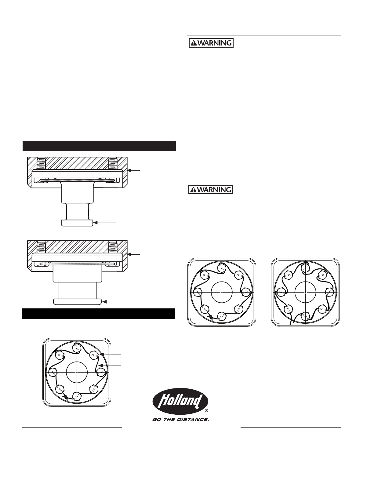
2. Insert the kingpin fully into the housing, taking care to
keep it in line to prevent binding. Rotate the kingpin to
lign bolt holes and install all bolts until hand tight.
a
Continue tightening, alternating across the bolt pattern
to insure uniform fit. Tighten all bolts to 180-200 foot
pounds. Recheck torque on all bolts a second time.
3. After bolts have been properly torqued, wind wire
through holes in bolt heads as shown in
Figure 1. Feed
the wire through the bolt from the center of the kingpin
out, moving clockwise from bolt to bolt. Wire should be
pulled tight with no slack between bolts. When finished
winding, end of wire should be adequately wound with
the beginning, so as not to come loose.
Lock wire must be installed for a secure
installation. Do not use without lock
wire installed correctly. Failure to correctly install lock wire
may allow bolts to loosen during operation causing kingpin
failure, resulting in separation of the towed vehicle and
subsequent property damage, personal injury or death.
IMPORTANT: Lock wire integrity must be checked every
6 months. Replace if damaged, broken or missing, using
parts from RK-0882 kit and the preceding instructions.
Correct Wrong
REPLACEMENT P
ARTS
RK-0882............Bolt and wire lock kit
Includes one wire lock and 8 bolts
Holland USA, Inc. Facilities:
Dumas, AR Muskegon, MI
Holland, MI Warrenton, MO
Monroe, NC Wylie, TX
Ph: 888-396-6501 Fax: 800-356-3929
2 XL-KP104-01 Rev A
Holland International, Inc.
Holland, MI
Phone:
Fax:
Copyright © August 2006 • The Holland Group, Inc.
Holland Hitch of Canada, Ltd.
616-396-6501
616-396-1511
Woodstock, Ontario • Canada
Phone:
Fax:
• Wire is tight • Wire is loose
• Wire ends are tied • Wire ends are not tied
Wire is wound in • Wire is wound
•
correct direction in wrong direction
These products are covered by Holland's Commercial
Products Warranty. Holland reserves the right, without
giving prior notice, to change specifications and
dimensions as designs are altered or improved.
Holland Equipment, Ltd.
519-537-3494
800-565-7753
Norwich, Ontario • Canada
Phone:
Fax:
Figure 1 Lock Wire Installation
Holland Hitch of Canada, Ltd.
519-863-3414
519-863-2398
Surrey, British Columbia • Canada
Phone:
Fax:
www.thehollandgroupinc.com
604-574-7491
604-574-0244
 Loading...