

Holland FW0070, FW1226, FW0100, FW1560, FW1900 Installation, Operation And Maintenance Manual
...
XL-FW482 Rev C
FW0070, FW0100, FW0165,
FW1226, FW1560, FW1900,
FW2000, FW2500, FW2555,
FW2570, FW2870, FW7040,
FW7090 Fifth Wheel
Installation, Operation, and
Maintenance Procedures
Owners Manual
English
2
XL-FW482 Rev C · 2016-07-05 · Amendments and Errors Reserved · © SAF-HOLLAND, Inc., SAF-HOLLAND, HOLLAND, SAF,
and logos are trademarks of SAF-HOLLAND S.A., SAF-HOLLAND GmbH, and SAF-HOLLAND, Inc.
Contents
Contents Page
Introduction ................................................... 2
Notes, Cautions, and Warnings ....................... 2
Section 1 – General Safety ............................. 3
Section 2 – Installation ..................................4
Section 3 – Stationary Fifth
Wheel Installation ........................6
Section 4 – Sliding Fifth Wheel Installation ..... 9
Section 5 – Inspection and Lubrication
Prior to Use ...............................14
Section 6 – Operating Instructions ...............14
Section 7 – Coupling Procedures ..................14
Section 8 – Uncoupling Procedures ..............16
Contents .................................................. Page
Section 9 – Sliding Procedure For a
Sliding Fifth Wheel .....................17
Section 10 – Maintenance Procedures ..........18
Section 11 – As Needed Lubrication .............18
Section 12 – Periodic Inspection
and Adjustment .......................18
Section 13 – Fifth wheel Locking Mechanism
Inspection and Adjustment ....... 18
Section 14 – Re-Lubricate After Inspection
and Adjustment .......................19
Section 15 – Sliding Mechanism Inspection
and Adjustment .......................20
Introduction
This manual provides you information necessary for
the proper installation of HOLLAND® Fifth Wheels.
NOTE: For technical support and genuine
HOLLAND® fifth wheel replacement
components contact SAF-HOLLAND®
Customer Service at:
1.888.396.6501
+86.592.6388.891
Notes, Cautions, and Warnings
Throughout this manual, you will notice the
terms “NOTE,” “IMPORTANT,” “CAUTION,”
and “WARNING” followed by useful product
information. So that you may better understand
the manual, those terms are defined as follows:
NOTE: Includes additional information
to enable accurate and easy
performance of procedures.
IMPORTANT: Includes additional
information that if
not followed could
lead to hindered
product performance.
Used without the safety
alert symbol, indicates
a potentially hazardous
situation which, if not
avoided, could result in
property damage.
Indicates a potentially
hazardous situation which,
if not avoided, could result
in minor or moderate injury.
Indicates a potentially
hazardous situation which,
if not avoided, could result
in death or serious injury.
Read and observe all Warning and Caution
hazard alert messages in this publication.
They provide information that can help
prevent serious personal injury, damage
to components, or both.

3
XL-FW482 Rev C · 2016-07-05 · Amendments and Errors Reserved · © SAF-HOLLAND, Inc., SAF-HOLLAND, HOLLAND, SAF,
and logos are trademarks of SAF-HOLLAND S.A., SAF-HOLLAND GmbH, and SAF-HOLLAND, Inc.
General Safety
1. General Safety
It is important to read, understand, and follow
the important information contained in these
installation instructions. Failure to do say may
result in a hazardous condition or cause a
hazardous condition to develop.
All welding should be performed by an AWS
certified welder using a low hydrogen process
and AWS E70XX filler metal. Failure to weld
correctly may cause distortion, damage, and/or
result in insufficient strength and subsequent
joint failure which, if not avoided, could result
in death or serious injury.
Prior to welding take precaution to ensure that
the tractor electrical system is not damaged
due to the welding process.
1. Keep work area clean. cluttered areas and
benches invite accidents.
2. Keep fingers away from all potential pinch
points in the fifth wheel.
3. All fifth wheel maintenance MUST be
performed by a qualified service technician
using proper tools and safety procedures.
4. Use SAF-HOLLAND® Parts only.
5. Use safety goggles. Glasses or goggles not
in compliance with ANSI or CSA can cause
serious injury when damaged or broken.
6. Wear proper apparel. DO NOT wear loose
clothing, gloves, neckties, jewelry (rings,
watches, etc.) that can get caught in moving
parts. Non-Slip footwear is recommended.
Fifth Wheel Design and Intended Use:
1. For pulling trailers with standard SAE
kingpins which are in good condition and
securely mounted or locked in position in
the trailer.
2. For on-highway hauling applications.
3. Within the capacities stated in SAFHOLLAND® Literature.
4. As Recommended in SAF-HOLLAND®
Literature (available from SAF-HOLLAND®
or SAF-HOLLAND® distributors).
HOLLAND® Fifth Wheels are NOT
Designed or Intended For:
1. Use with non-SAE kingpins, such as
kingpins which are bent, improper size or
dimensions, not secured to maintain SAE
configuration, or which are installed in
warped trailer bolster plates.
2. Tow-away operations which may damage
or interfere with the proper operation of
the fifth wheel.
3. The attachment of lifting devices.
4. The transport of loads in excess of rated
capacity.
5. Off-highway applications and use.
6. Applications other than recommended.

4
XL-FW482 Rev C · 2016-07-05 · Amendments and Errors Reserved · © SAF-HOLLAND, Inc., SAF-HOLLAND, HOLLAND, SAF,
and logos are trademarks of SAF-HOLLAND S.A., SAF-HOLLAND GmbH, and SAF-HOLLAND, Inc.
Installation Procedures
2. Installation
2.1 General Recommendations
1. Every user and installer using HOLLAND®
products either recommended or not
recommended by HOLLAND®, MUST
thoroughly satisfy him/herself that the
installation procedure used is appropriate
for the vehicle, product and application.
2. Consult the HOLLAND® literature for fifth
wheel capacities and applications.
3. Consult the tractor manufacturer's body
builder's book and the latest SAE and
D.O.T. Standards for additional installation
methods. HOLLAND® recommends the
T.M.C. Recommended Maintenance
Practice 603B for installation
procedures.
4. Determine the proper fifth wheel position,
or, in the case of a sliding fifth wheel,
the range of proper positions. Proper
positioning of a fifth wheel is important for
weight distribution, swing clearance and
handling characteristics. Refer to SAE J701a
for proper placement, as well as the tractor
manufacturer's body builder's book.
5. Use Grade 8, 5/8" minimum diameter
bolts and Grade “C” locknuts for
mounting.
6. Bolt holes can be 1/32" larger in diameter
than the bolt fastener. Bolts MUST be
adequately tightened using torque ranges
in foot-pounds for the recommended
Grade 8, 5/8" diameter bolts. Larger
diameter Grade 8 bolts and coated
fasteners may be used.
7. The bolts attaching the fifth wheel
mounting angles to the truck frame
require hardened steel washers under
both the bolt and under the locknut,
unless flanged head bolts or flanged head
locknuts are employed.
8. A minimum of 5 bolts are required to
attach each mounting angle to the frame
rail, and the distance between bolts MUST
NOT exceed 8", except when cutouts are
required in the mounting angles.
9. Whenever a cutout is made on the
mounting angle, such as required to by
pass spring hangers, a 1" minimum radius
should be used and bolts should be placed
within 1 1/2", but not closer than 1" of
the cut, fore and aft.
10. The mounting angle should have a minimum
thickness as shown in Table 1 and should be
steel specification ASTM A 36
11. When initially positioning the fifth wheel
for frame holes, the full length of the fifth
wheel or slider mounting angles should
seat flush on the top and side surface of the
truck-tractor frame rails where channel-type
rails are employed. There should NOT be a
gap over the top of the truck frame rails.
The base of the fifth wheel assembly and
of the mounting angle members should
seat flush on the top of the frame rail to
prevent flexing and to give uniform weight
distribution. It is also recommended to
chamfer or smooth sharp edges and corners
of mounting materials wherever contact is
made with the tractor frame.
5
XL-FW482 Rev C · 2016-07-05 · Amendments and Errors Reserved · © SAF-HOLLAND, Inc., SAF-HOLLAND, HOLLAND, SAF,
and logos are trademarks of SAF-HOLLAND S.A., SAF-HOLLAND GmbH, and SAF-HOLLAND, Inc.
12. If the fifth wheel is to be mounted using
a mounting plate (bracket with mounting
base), refer to TABLE 1 for minimum
plate thickness recommendations.
DO NOT use U-bolts in fifth
wheel installations. Use only
new Grade 8 bolts and new
Grade C lock nuts, sized 5/8"
minimum diameter. Failure to
do so may result in structural
failure of the installation with a
potential loss of the fifth wheel
assembly, mounting structure,
and/or trailer and may result in
death or serious injury.
Installation Procedures
Fifth Wheel
Vertical Capacity
Minimum Mounting
Angle Thickness
Minimum Mounting
Plate Thickness
12,000 lbs.
1/4" 1/4"
20,000 lbs.
5/16" 1/4"
40,000/45,000 lbs.
5/16" 5/16"
50,000/55,000 lbs.
3/8" 3/8"
62,500/70,000 lbs.
1/2" 1/2"
100,000 lbs.
3/4" 3/4"
165,000 lbs. 3/4" 1"
Table 1
13. Trailer pick-up ramps are recommended at
the rear of the truck-tractor frame.
14. When mounting to aluminum frames,
follow the tractor manufacturer's
recommendations. HOLLAND® has available
a stationary mounting angle intended for
use with aluminum frames. Contact
SAF-HOLLAND® and SAF-HOLLAND®
distributors for availability.
15. Review, in addition the specific
information on the following pages for
each type of fifth wheel mounting, as well
as “Inspection and Lubrication Prior to
Use” on page 13 of this publication.
6
XL-FW482 Rev C · 2016-07-05 · Amendments and Errors Reserved · © SAF-HOLLAND, Inc., SAF-HOLLAND, HOLLAND, SAF,
and logos are trademarks of SAF-HOLLAND S.A., SAF-HOLLAND GmbH, and SAF-HOLLAND, Inc.
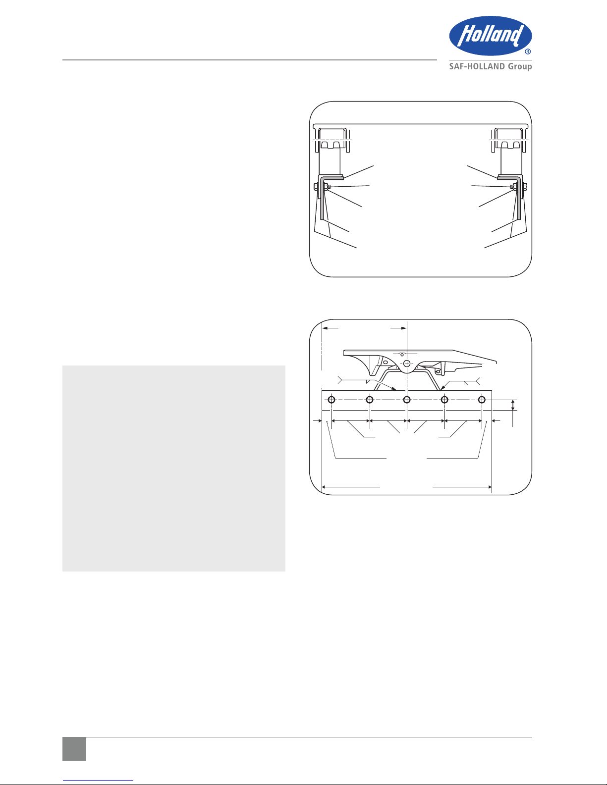
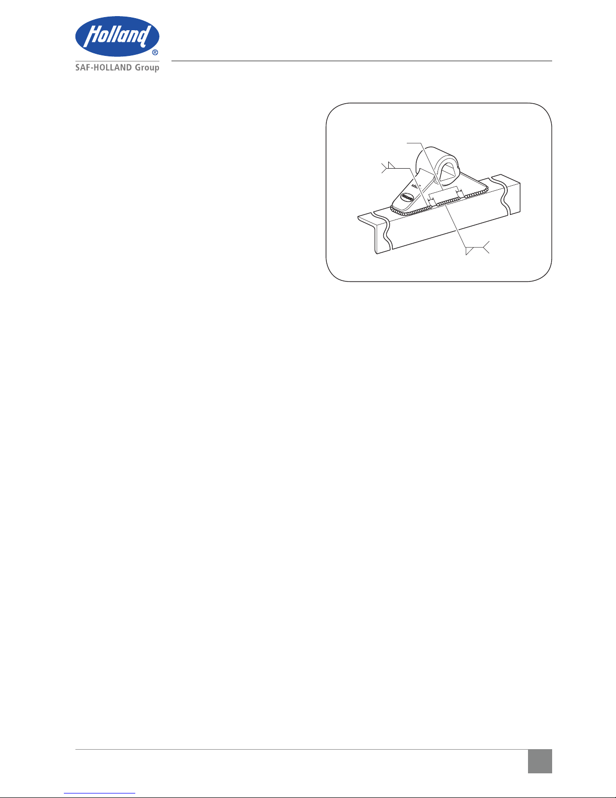
Figure 1
Installation Procedures
3. Stationary Fifth
Wheel Installation
Prior to proceeding with the installation of
the stationary fifth wheel assembly, carefully
review the “General Safety Information”
Section on page 3.
3.1 Bracket with Mounting Angle
1. HOLLAND® brackets with mounting angle
are provided with the bracket welded in
the center of the 36" long angle with a 4"
minimum horizontal and 3 1/2" minimum
vertical leg size, and to a specific tractor
frame width. Verify that the bracket and
tractor frame width are the same.
2. In addition to the information given in
"Installation: General Recommendations"
on page 4, follow the recommendations
in Figure 1, 2, and 3.
IMPORTANT: The full length of the fifth
wheel mounting angle
should seat flush on the
truck frame when mounting
to prevent flexing of the
mounting angle and to give
uniform weight distribution
along the truck frame rail
(Figure 1).
IMPORTANT: Use 5/8" Grade 8 bolts and
Hardened steel washers or
flanged locknuts (Figure 1).
Torque according to bolt
manufacturer charts.
3.2 Bracket for Angle Mounting
1. HOLLAND® brackets for angle mounting
are intended to be welded to mounting
angles at the time of installation.
Figure 2
HARDENED STEEL WASHERS
REFER TO TABLE 1 FOR
MOUNTING ANGLE THICKNESS
5/8" GRADE 8 BOLTS
TRUCK FRAME RAIL
5/8" GRADE C LOCKNUTS
36.00" MIN
(914.4 mm)
2.00" MIN
(50.8 mm)
18.00" MIN
(457.2 mm)
8.00" MAX TYP.
(203.2 mm)
BOTH
SIDES
1" MIN
(24 mm)
1/4" 1/2"
DOUBLE
PASS MIN.
BOTH ENDS
7
XL-FW482 Rev C · 2016-07-05 · Amendments and Errors Reserved · © SAF-HOLLAND, Inc., SAF-HOLLAND, HOLLAND, SAF,
and logos are trademarks of SAF-HOLLAND S.A., SAF-HOLLAND GmbH, and SAF-HOLLAND, Inc.
Installation Procedures
2. Refer to "Installation: General
Recommendations" on page 4, for angle
thickness and material (use 4" minimum
horizontal and 3-1/2" minimum vertical
leg size). The recommended length of each
mounting angle is 36". it is recommended
that each angle extend at minimum length
of 18" forward of the fifth wheel pivot
point, and not less than 12' to the rear
(Figure 2). If angles shorter than 36"
are required, the special recommendations
of the tractor manufacturer should be
obtained.
3. In addition to the information given in
"Installation: General Recommendations,"
follow the recommendations given in
Figures 1, 2, and 3. The following
sequence is suggested for both fabricated
and cast brackets:
a. Securely position the mounting angle
to the tractor frame.
b. Bolt the angles to the tractor as
illustrated (Figure 1 and 2).
c. Position the brackets on the angles
and verify the correct spacing to
mount the fifth wheel.
d. For fabricated brackets (welded
assembly), weld the bracket to the
mounting angle with 1/4" fillet
welds on both sides, and 1/2"
groove welds on both ends, as
illustrated (Figure 1 and 2).
The welds should be continuous
around the bracket and joined at
the corners.
e. For cast brackets (single piece), weld
with 5/16" fillet weld as illustrated
(Figure 3). The welds MUST be
continuous around the bracket ends.
Figure 3
BOTH SIDES
CENTER OF
BRACKET
GAP 1/4" - 1/2" IN
FOUR (4) PLACES
WELDING DETAILS
(CAST BRACKETS ONLY)
BOTH ENDS
CONTINUOUS
3"
5/16"
5/16"
8
XL-FW482 Rev C · 2016-07-05 · Amendments and Errors Reserved · © SAF-HOLLAND, Inc., SAF-HOLLAND, HOLLAND, SAF,
and logos are trademarks of SAF-HOLLAND S.A., SAF-HOLLAND GmbH, and SAF-HOLLAND, Inc.
Installation Procedures
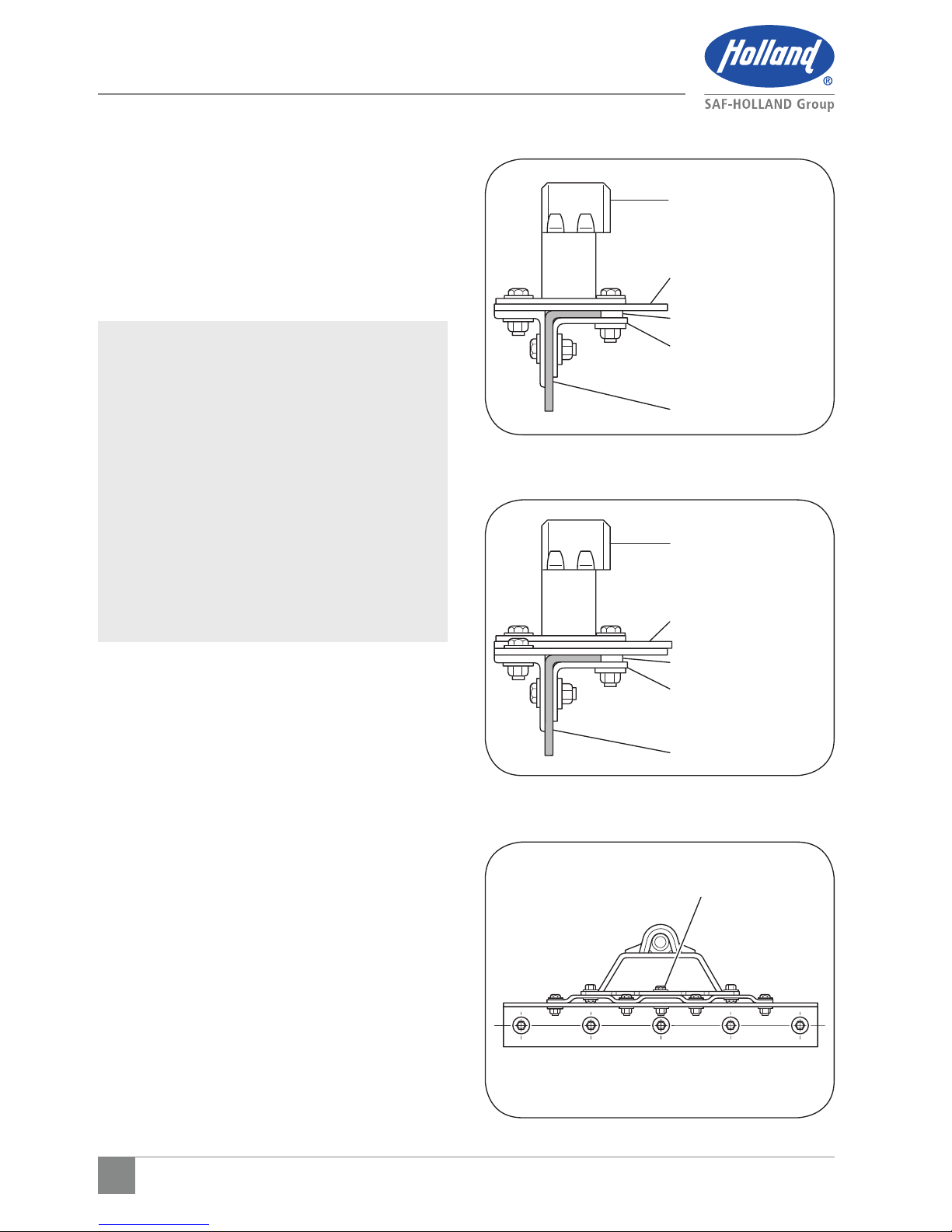
3.3 Bracket with Mounting Base
1. HOLLAND® brackets with mounting base
are intended for installation on either
corrugated or flat mounting plates.
2. In addition to the information given in
"Installation: General Recommendations"
on Page 4, follow the recommendations in
Figures 4, 5, and 6.
IMPORTANT: Attach the outboard angle to
tractor frame with hardware
listed in Figure 1. Attach
mounting plate to angle with
the same number of bolts (in
addition to attachment to
fifth wheel support bracket)
(Figure 4 and 5).
IMPORTANT: Attach bracket and mounting
plate as illustrated (Figure
6). Use center bolt of
sufficient length to bolt
through bracket, mounting
plate and mounting angle.
3. Refer to "Installation: General
Recommendations," on page 4, for angle
thickness and material. The mounting
angle should be 1" longer than the
mounting plate, and be 36" minimum
length. Use 3" minimum horizontal and
3-1/2" minimum vertical leg size. Longer
horizontal legs may be required with
narrow frame widths.
Figure 5
Figure 6
Figure 4
FIFTH WHEEL
SUPPORT BRACKET
FIFTH WHEEL
SUPPORT BRACKET
FLAT MOUNTING
PLATE REFER TO TABLE
1 FOR MINIMUM
THICKNESS
CORRUGATED
MOUNTING PLATE
REFER TO TABLE 1 FOR
MINIMUM THICKNESS
SPACER
SPACER
TRACTOR FRAME
TRACTOR FRAME
CENTER BOLT
INBOARD ANGLE
INBOARD ANGLE
 Loading...