

Holland Atlas 55, Atlas 65, Atlas iM Installation, Operation And Maintenance Manual
Installation, Operation
and Maintenance Manual
Atlas 55, Atlas 65 and Atlas iM
XL-LG20004UM-en-US Rev B
Contents
Contents Page
Introduction ..........................................................................2
Warranty ...............................................................................2
Notes, Cautions, and Warnings ..............................................2
Section 1 – Safety Instructions ..............................................3
Section 2 – Model and Serial Number .................................. 4
Section 3 – Pre-Installation Instructions ............................... 6
Section 4 – Recommended Bracing....................................... 7
Section 5 - Welding Standards .............................................. 8
Section 6 – Installation Instructions ..................................... 9
Section 7 – Landing Gear Operation ................................... 10
Section 7.1 – Pre-Inspection ............................................... 10
Introduction
This manual provides information necessary for the installation,
operation and maintenance of the SAF-HOLLAND® Atlas 55, 65 and
iM model landing gears.
Read this manual before using or servicing this product and
keep it in a safe location for future reference. Updates to this
manual, which are published as necessary, are available on
the internet at www.safholland.us.
Contents Page
Section 7.2 – Landing Gear Orientation .............................. 10
Section 7.3 – Landing Gear Operation During Coupling ...... 11
Section 7.4 – Landing Gear Operation During Uncoupling .. 12
Section 8 – Routine Service and Inspection ........................ 14
Section 8.1 – Landing Gear Inspection (Before Use)............ 14
Section 8.2 – Lubrication ................................................... 14
Section 8.3 – Cleaning ....................................................... 14
Section 8.4 – Hardware Inspection ..................................... 15
Section 8.5 – Landing Gear Alignment................................ 15
Section 9 – Troubleshooting ............................................... 16
Notes, Cautions, and Warnings
Before starting any work on the unit, read and understand all
the safety procedures presented in this manual. This manual
contains the terms “NOTE”, “IMPORTANT”, “CAUTION”, and
“WARNING” followed by important product information. These
terms are defined as follows:
NOTE: Includes additional information to enable accurate
and easy performance of procedures.
When replacement parts are required, SAF-HOLLAND® highly
recommends the use of only SAF-HOLLAND® Original Parts. A
list of technical support locations that supply SAF-HOLLAND®
Original Parts and an Aftermarket Parts Catalog are available
on the internet at www.safholland.us or contact Customer
Service at 888-396-6501.
Warranty
Refer to the complete warranty for the country in which
the product will be used. A copy of the written warranty is
included with the product or available on the internet at
www.safholland.us.
IMPORTANT: Includes additional information that if
not followed could lead to hindered
product performance.
Used without the safety alert symbol,
indicates a potentially hazardous
situation which, if not avoided, could
result in property damage.
Indicates a potentially hazardous
situation which, if not avoided, could
result in minor or moderate injury.
Indicates a potentially hazardous
situation which, if not avoided, could
result in death or serious injury.
2
XL-LG20004UM-en-US Rev B · 2018-09-17 · Amendments and Errors Reserved · © SAF-HOLLAND, Inc., SAF-HOLLAND, HOLLAND, SAF,
and logos are trademarks of SAF-HOLLAND S.A., SAF-HOLLAND GmbH, and SAF-HOLLAND, Inc.

1. Safety Instructions
General and Servicing Safety Instructions
Read and observe all Warning and Caution hazard
alert messages. The alerts provide information that
can help prevent serious personal injury, damage to
components, or both.
Failure to follow the instructions and safety
precautions in this manual could result in
improper servicing or operation leading to
component failure which, if not avoided,
could result in death or serious injury.
All maintenance should be performed by a properly
trained technician using proper/special tools, and
safe procedures.
NOTE: In the United States, workshop safety requirements
are defined by federal and/or state Occupational
Safety and Health Act (OSHA). Equivalent laws may
exist in other countries. This manual is written based
on the assumption that OSHA or other applicable
employee safety regulations are followed by the
location where work is performed.
IMPORTANT: Verify before installation that the landing
gear selected will withstand the load
and have the correct travel/extension
requirements for the trailer.
DO NOT operate the landing gear if it is cracked,
bent, or any other damage is present. Using damaged
landing gear could result in death or serious injury.
Failure to check condition of landing gear
prior to operating could result in unexpected
performance which, if not avoided, could
result in death or serious injury.
Safety Instructions
Properly support and secure the vehicle from unexpected
movement when servicing the landing gear.
NOTE: If possible, unload the trailer before performing any
service procedures.
Failure to secure the trailer from rolling, when
operating the landing gear, could result in
death, serious injury or property damage.
Failure to properly support and secure
the trailer during installation of landing
gear could create a crush hazard which,
if not avoided, could result in death or
serious injury.
DO NOT walk/crawl underneath a trailer during
coupling/uncoupling or while it is supported by the
landing gear/kingpin stand.
If possible, unload the trailer before performing any
maintenance or service procedures.
Failure to keep clear from underneath the
trailer could create a crush hazard which,
if not avoided, could result in death or
serious injury.
Using damaged landing gear could
result in unexpected performance which,
if not avoided, could result in death or
serious injury.
XL-LG20004UM-en-US Rev B · 2018-09-17 · Amendments and Errors Reserved · © SAF-HOLLAND, Inc., SAF-HOLLAND, HOLLAND, SAF,
and logos are trademarks of SAF-HOLLAND S.A., SAF-HOLLAND GmbH, and SAF-HOLLAND, Inc.
3
Model Identification
2. Model Identification
Atlas 55
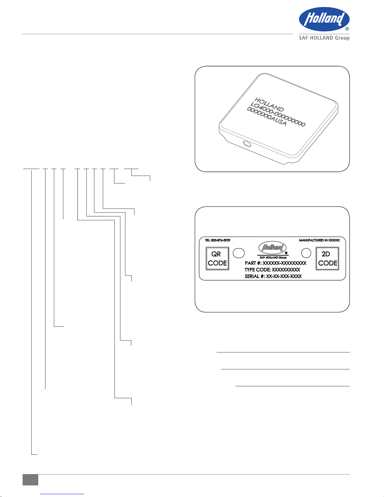
The Atlas 55 identification code is located on the top cover or
on the side, behind the grease fittings of each landing gear
leg (Figure 1 and 2). The first number is the part number,
described below, and the second number is the serial number. In
order to properly identify the HOLLAND® landing gear and its
components when communicating with SAF-HOLLAND® or a
dealer, please record the part and serial numbers below and
refer to them when ordering replacement parts.
Part Number
LG4 0 0 1 - 7 0 0 0 00 000
Log No. Accessory No.
Contact SAF-HOLLAND®
Customer Service for Special
Options and Accessories
Footware
0 - No Footware
1 - Sandshoe 4.50"x 10"x 10"
2 - Sandshoe 4.50"x 10"x 12"
3 - Sandshoe 2"x 10"x 10"
4 - Sandshoe 2"x 10"x 12"
5 - Shockfoot DIA 12"
8 - Shockfoot DIA 10"
9 - Special
A - R.C.F. No Footware
B - R.C.F. 10" x 10"
C - R.C.F. DIA 10"
D - R.C.F. DIA 12"
M - Sandshoe HD 4.50"x 12"x 12"
R - R.C.F. 12"x 12"
S - R.C.F. 10"x 10" Heavy Duty
Z - 10" x 10" Low Profile RCF
Shafts
0 - Universal
1 - Reverse
2 - I-Beam 6.5"
8 - Special
9 - Conventional
A - I -Beam 10"
J - Universal EZ Shift
K - Conventional EZ Shift
L - Reverse EZ Shift
M - I-Beam EZ Shift
Mounting
0 - Univ.Mt.-.66"Ø Holes
1 - Conv. Mt.- .66" Ø Holes
4 - I-Beam Mt. - .66" Ø Holes
8 - Reverse Mt. - .66" Ø Holes
9 - Special
A - Univ. Mt.- .53" Ø Holes
B - Conv. Mt. - .53" Ø Holes
H - I-Beam Mt. - .53" Ø Holes
L - Reverse Mt.- .53" Ø Holes
Model
LG4 - Atlas 55
Grease
0 - Standard Pack
9 - Special
Q - No Lube™
(Permanently Lubricated)
S - No Lube™
(Lifetime Warranty)
F - 45° Fittings
G - 4 Straight Fittings Per Leg
Retract Tube
0 - Standard
5 - R.C.F. MRL
6 - Shock Can
9 - Special
B - Min. Retracted
Shockfoot and
Low Profile RCF
Leg Assembly
0 - Sets
1 - Left Hand
2 - Right Hand
Travel
1 - Special
3 - 13.50"
5 - 15.50"
7 - 17"
9 - 19"
Figure 1
Figure 2
Part No:
Serial No:
Purchase Date:
4
XL-LG20004UM-en-US Rev B · 2018-09-17 · Amendments and Errors Reserved · © SAF-HOLLAND, Inc., SAF-HOLLAND, HOLLAND, SAF,
and logos are trademarks of SAF-HOLLAND S.A., SAF-HOLLAND GmbH, and SAF-HOLLAND, Inc.
Model Identification
Atlas 65
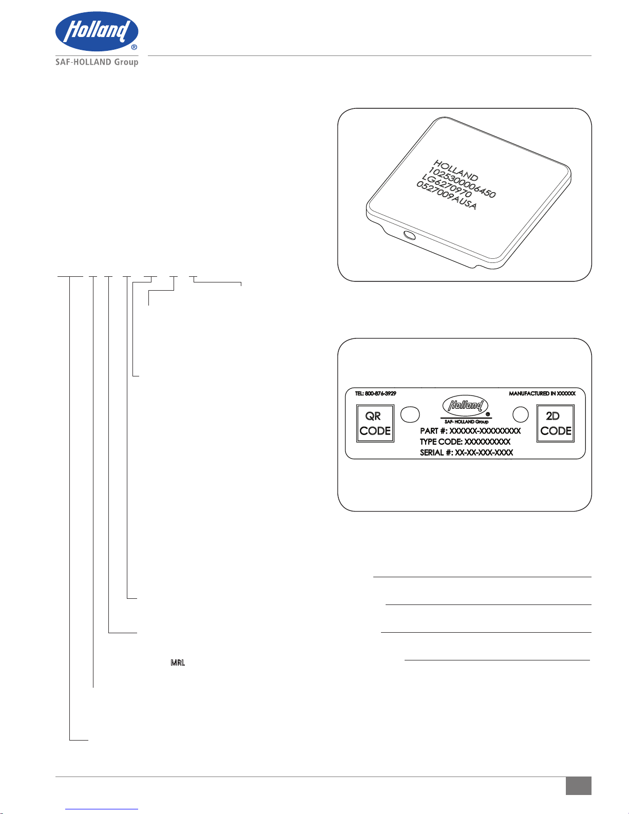
The Atlas 65 identification code is located on the top cover
or on the side, behind the grease fittings, of each landing gear
leg (Figure 3 and 4). The first number is the part number,
the second number is the type code, and the third number is
the serial number. In order to properly identify the HOLLAND®
landing gear and its components when communicating with
SAF-HOLLAND® or a dealer, please record the part number, type
code, and serial number and refer to them when ordering
replacement parts.
Type Code
LG6 0 0 0 00 0 0
Lube/Warranty
0 - Std. Lube
Shafts
0 - Standard Universal
1 - Standard Inside
2 - Outside I-Beam 6.5"
3 - Outside I-Beam 10"
4 - Standard Outside
Foot Ware
99 - No Foot
98 - Leg with Axle - No Foot
97 - Sand Shoe 4.5" x 10" x 10"
96 - Sand Shoe 4.5" x 10" x 12"
95 - Sand Shoe 2"x 10" x 10"
94 - Sand Shoe 2" x 10" x 12"
93 - Sand Shoe HD 4.5" x 12" x 12"
92 - Standard RCF 10"x 10"
91 - Low Profile RCF
90 - For RCF - No Foot
89 - Low Profile RCF - No Foot
88 - Sand Shoe 4.5" x 16" x 16"
87 - Sand Shoe LP 2" x 12" x 12"
86 - Sand Shoe STD 4.5" x 12" x 12"
85 - Sand Shoe HD 4.5" x 12" x 17"
84 - Sand Shoe HD 4.5" x 12" x 10"
83 - Sand Shoe HD - LP 2" x 10" x 10"
82 - Sand Shoe HD 4.5" x 10" x 10"
81 - Standard RCF 12" x 12"
80 - Sand Shoe 4.5" x 18" x 16"
79 - Sand Shoe LP 2" x 16" x 16"
Mounting Plate
0 - Standard Taper .656" Ø
1 - Standard Taper .531" Ø
Travel
3 - 13.5"
5 - 15.5"
6 - 17" - MRL
7 - 17"
9 - 19"
Leg Assembly
0 - Sets
1 - Leg Without Gear Box
2 - Leg With Gear Box
Model
LG6 - Atlas 65
Std. Warranty
1 - No Lube™
Std. Warranty
2 - No Lube™
Lifetime Warranty
Figure 3
Figure 4
Part No:
Type Code:
Serial No:
Purchase Date:
XL-LG20004UM-en-US Rev B · 2018-09-17 · Amendments and Errors Reserved · © SAF-HOLLAND, Inc., SAF-HOLLAND, HOLLAND, SAF,
and logos are trademarks of SAF-HOLLAND S.A., SAF-HOLLAND GmbH, and SAF-HOLLAND, Inc.
5

Model Identification
Atlas iM
The Atlas iM identification code is located on the top cover
or on the side, behind the grease fittings, of each landing gear
leg (Figure 5 and 6). The first number is the part number,
the second number is the type code, and the third number is
the serial number. In order to properly identify the HOLLAND®
landing gear and its components when communicating with
SAF-HOLLAND® or a dealer, please record the part number, type
code, and serial number and refer to them when ordering
replacement parts.
Type Code
LG6 0 0 0 00 0 0
Lube/Warranty
Shafts
2 - Outside I-Beam 6.5"
3 - Outside I-Beam 10"
4 - Standard Outside
Foot Ware
92 - Standard RCF 10" x 10"
83 - Sand Shoe HD - LP 2" x 10" x 10"
1 - No Lube™
Std. Warranty
2 - No Lube™
Lifetime Warranty
Figure 5
Figure 6
Mounting Plate
0 - Standard Taper .656" Ø
1 - Standard Taper .531" Ø
Travel
3 - 13.5"
5 - 15.5"
6 - 17" - MRL
7 - 17"
9 - 19"
Leg Assembly
0 - Sets
1 - Leg Without Gear Box
2 - Leg With Gear Box
Model
LG6 - Atlas iM
Part No:
Type Code:
Serial No:
Purchase Date:
6
XL-LG20004UM-en-US Rev B · 2018-09-17 · Amendments and Errors Reserved · © SAF-HOLLAND, Inc., SAF-HOLLAND, HOLLAND, SAF,
and logos are trademarks of SAF-HOLLAND S.A., SAF-HOLLAND GmbH, and SAF-HOLLAND, Inc.
 Loading...