

Page 1
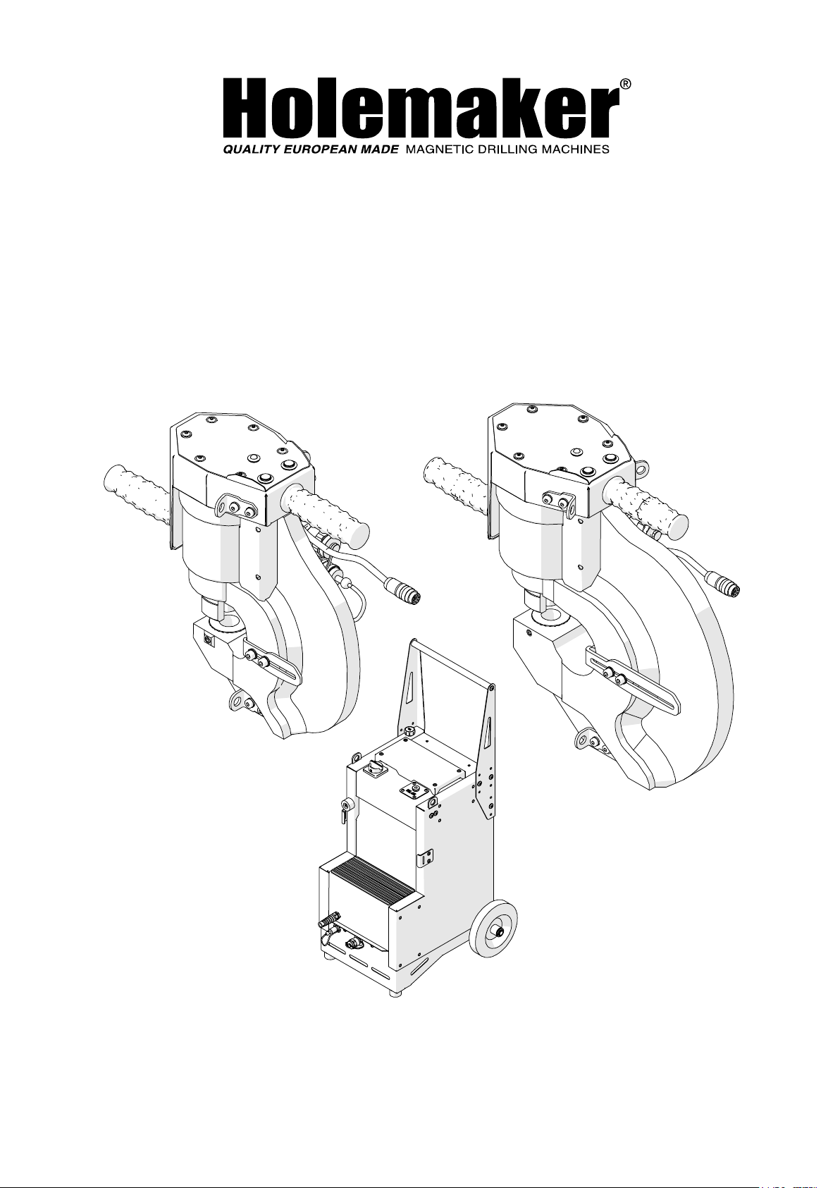
PUNCHER PRO 60 HP, PRO 110 HP
HYDRAULIC POWER PACK HPP 700/1.5
OPERATOR’S MANUAL
BEFORE USE, ENSURE EVERYONE USING THIS MACHINE READS AND UNDERSTANDS
ALL SAFETY AND OPERATING INSTRUCTIONS IN THIS MANUAL .
Serial #............................................ Date of Purchase............................
Page 2

HOLEMAKER PRO 60 HP, PRO 110 HP & HPP 700/1.5
IMPORTED & DISTRIBUTED BY
INDUSTRIAL TOOL & MACHINERY SALES
18 BUSINESS ST
YATALA QLD 4207 AUSTRALIA
07 3287 1114
T
07 3287 1115
F
E
www.industrialtool.com.au
W
WARRANTY TERMS
In addition to any warranties or conditions implied by applicable Statute or Regulations, Industrial
Tool & Machinery Sales warrants all of it’s products against defective workmanship and faulty
materials for a period of twelve (12) months from the date of purchase, unless otherwise stated.
At our option we will repair or replace, free of charge, any item on the condition that:
• The complete machine or tool is returned, freight prepaid to ITM or one of it’s authorised
service agents as directed by ITM, and is found to have a material or constructional defect.
• The machine or tool has not been subject to misuse, neglect or damage by accident.
• The fault is not a result of normal “wear and tear”.
• Written permission has been received from ITM prior to commencement of repair.
• Repairs, tampering or modification carried out by unauthorised personnel will void all warranty.
• Consumable items such as cutting tools, pilot pins, saw blades, grinding wheels etc. are NOT
covered by warranty.
Our goods come with guarantees which cannot be excluded under the Australian Consumer
Law. You are entitled to replacement or refund for a major failure and to compensation for other
reasonably foreseeable loss or damage. You are also entitled to have the goods repaired or
replaced if the goods fail to be of acceptable quality and the failure does not amount to a major
failure.
2
Page 3

HOLEMAKER PRO 60 HP, PRO 110 HP & HPP 700/1.5
TABLE OF CONTENTS
1. GENERAL INFORMATION - 4 -
1.1. Application - 4 -
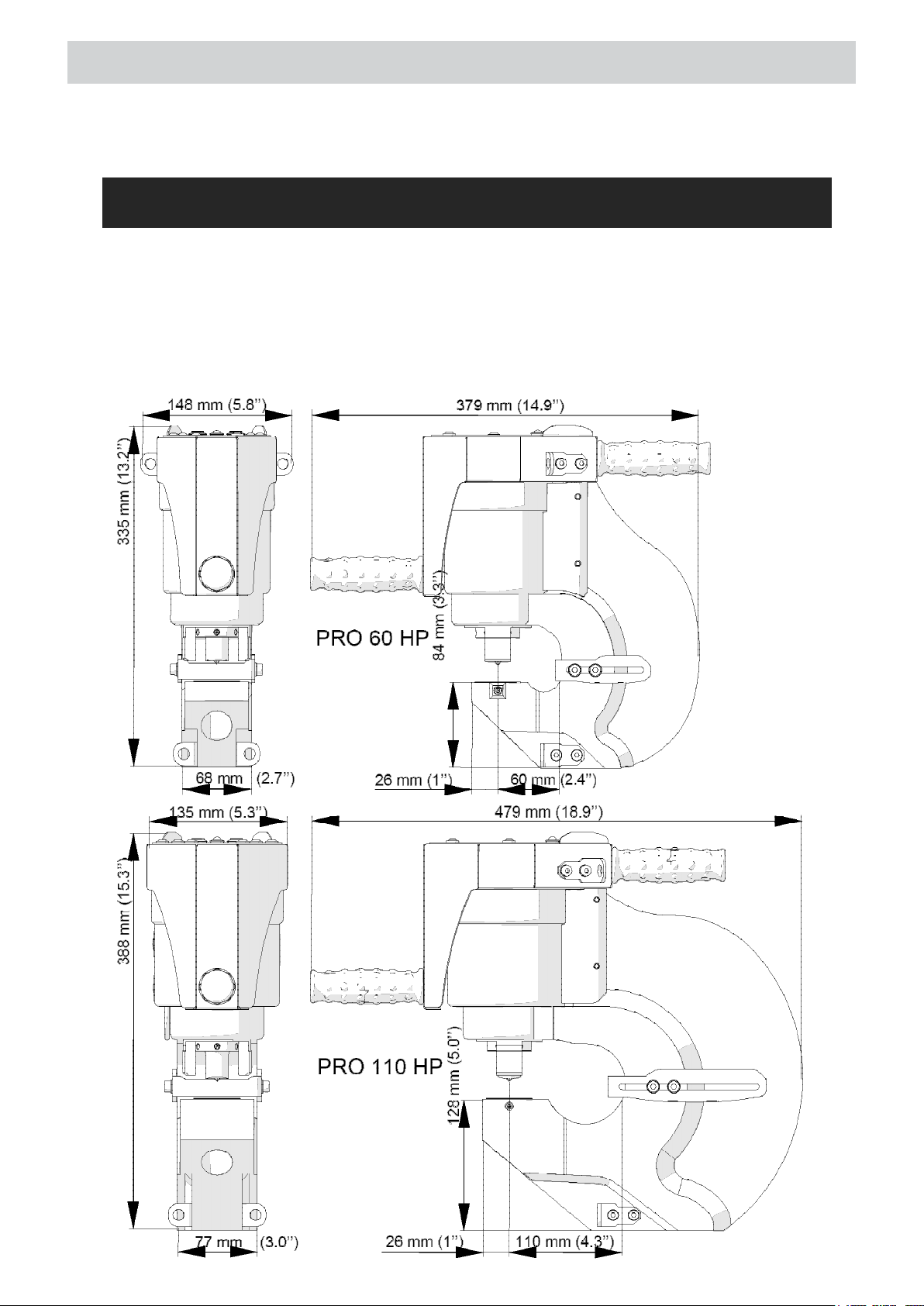
1.2. Technical data - 4 -
1.3. Maximum plate thickness - 6 -
1.4. Selecting punches for the most common inch plates - 9 -
1.5. Allowed parameters of extension cords - 11 -
1.6. Design - 13 -
1.7. Equipment included - 14 -
1.5. Transportation - 14 -
2. SAFETY PRECAUTIONS - 15 -
3. START UP AND OPERATION - 16 -
3.1. Mounting the punch and die - 16 -
3.2. Connecting the hydraulic power pack - 17 -
3.3. Positioning - 18 -
3.4. Punching - 19 -
3.5. Replacing the die and punch - 19 -
3.6. Replacing the restrainer - 20 -
3.7. Troubleshooting - 21 -
4. ACCESSORIES - 23 -
4.1. Punches and dies - 23 -
4.2. Balancer - 24 -
4.3. Crane - 24 -
4.4. Stationary work set - 28 -
4.5. Guide - 30 -
4.6. Tool box - 32 -
5. WIRING DIAGRAM - 33 -
6. PARTS LIST - 34 -
6.1. PRO 60 HP Parts List - 34 -
6.2. PRO 110 HP Parts List - 38 -
6.3. HP 700 Parts List - 42 -
3
Page 4
GENERAL INFORMATION
1.1. Application
The Puncher is designed to punch circular holes with diameters of 7–27 mm and oblong
holes in metal plates using a cylinder driven by the HPP 700/1.5 Hydraulic Power Pack.
1.2. Technical data
4
Page 5

GENERAL INFORMATION
5
Page 6

GENERAL INFORMATION
6
Page 7

GENERAL INFORMATION
7
Page 8

GENERAL INFORMATION
8
Page 9

GENERAL INFORMATION
9
Page 10

GENERAL INFORMATION
10
Page 11

GENERAL INFORMATION
11
Page 12

GENERAL INFORMATION
12
Page 13

1.6. Design
GENERAL INFORMATION
13
Page 14

SAFETY INSTRUCTIONS
1.7. Equipment included
1.8. Transportation
14
Page 15

SAFETY PRECAUTIONS
2. SAFETY PRECAUTIONS
1. Before beginning, read this Operator’s Manual and complete proper occupational safety and
health training.
2. The machine must be used only with HPP 700/1.5 Hydraulic Power Pack.
3. The machine, hydraulic power pack, cables, and hoses must be used only in applications specifi ed
in this Operator’s Manual.
4. The machine and hydraulic power pack must be complete and all their parts must be genuine and
entirely operational.
5. The electrical supply specifi cations must conform to those specifi ed on the rating plate of the
hydraulic power pack.
6. The hydraulic power pack must be plugged into a properly grounded (earthed) socket-outlet. The
electrical supply must be protected with a C25 A fuse for 230 V or a C32 A fuse for 115 V.
7. Do not cover the air vents of the hydraulic power pack.
8. Never crush or pull cables and hoses as this may damage them and result in serious injury.
9. Arrange hoses so that there are no tripping hazards. Wrap the hoses around the power pack if
possible.
10. The bending radius of the high-pressure hose must never be less than 80 mm (3.2’’). If the hose is
bent to a smaller radius or has any signs of wear or damage, replace the hose immediately.
11. Untrained bystanders must not be present in the vicinity of the machine and hydraulic power pack.
12. Before beginning, check the condition of the machine, hydraulic power pack, and electrical supply,
including cables and hoses, connectors, sockets, plugs, punch, and die. Make sure the highpressure hydraulic hose is securely attached to the machine and power pack.
13. Keep the machine, hydraulic power pack, cables, and hoses dry. Exposure to direct sunlight, rain,
snow, or frost is prohibited.
14. Keep the work area well lit, clean, and free of obstacles.
15. Never use the machine in the vicinity of fl ammable liquids or gases, or in explosive environments.
16. Use only punches and dies specifi ed in this Operator’s Manual.
17. Mount punches and dies securely. Remove adjusting keys and wrenches from the work area
before powering the hydraulic power pack.
18. Before every use, inspect the machine and hydraulic power pack to ensure they are not damaged.
Check whether any part is cracked or improperly fi tted. Make sure to maintain proper conditions
that may aff ect the operation of the machine and hydraulic power pack.
19. Always use a safety helmet with shield, hearing protection, protective footwear, gloves, and
protective clothing during operation. Do not wear loose clothing.
20. Do not touch the punch or put hands into its work area.
21. Maintain the machine with care. Cover steel parts with a thin grease layer to protect them against
rust when not in use for any extended period.
22. Perform maintenance and replacement of the punch, die, and restrainer only with the power ON/
OFF switch set to position ‘0’.
23. Perform repairs only in a service center appointed by the seller.
24. If the machine falls on a hard surface, from height, is wet, or has any other damage that could
aff ect the technical state of the machine, stop the operation and immediately send the machine to
the service center for inspection and repair.
25. Never leave the machine or the hydraulic power pack unattended during operation.
26. Remove the machine and power pack from the worksite and store in an isolated and dry location
when not in use.
15
Page 16

START UP AND OPERATION
3. STARTUP AND OPERATION
All safety precautions must be closely observed.
3.1. Mounting the punch and die
Set the power ON/OFF switch to position ‘0’. Then, insert the nut joined with the punch into
the machine (1, Fig. 4), and screw the nut manually in direction 2, after which insert the
wrench into the hole (3) and lock the nut by rotating the wrench in the same direction. If an
oblong punch 4 is used, before locking the nut the punch pin must snap into the socket,
which will be indicated by a snap sound.
Retract the restrainer as far as possible (1, Fig. 5a), rest the die onto the drift (2), and lower
the drift to insert the die into the socket (3). Tighten with the 4 mm hex wrench (4). The
diameters (dimensions) of the punch and die installed must be the same. Position inclined
dies 5 and oblong dies 6 and 7 in such a way to align the groove with the set screw 4.
Mount oblong dies and oblong punches in the same orientation
16
Page 17

START UP AND OPERATION
3.2. Connecting the hydraulic power pack
Connect the machine with the hydraulic power pack using the hydraulic hoses and control
cable. To do this, remove caps from the hydraulic sockets of the machine, fi rmly screw the
high-pressure connector into the socket 1 (Fig. 6), and plug the low--pressure connector into the
socket 2 until it snaps into place. Then, connect the control cable to the connector 3 and plug
the power cord of the hydraulic power pack into the power outlet.
Every time the power pack is connected and the power ON/OFF switch is set to position
‘I’, the status LED will fl ash every 0.5 seconds indicating the need to press and hold the STOP/
UP button for about 3 seconds. This will cause the punch to retract fully if it is not already in this
position.
Use the 8 mm hex wrench to unscrew the transport cap 4 of the hydraulic power pack
and place the oil plug in cap’s position 5.
17
Page 18

START UP AND OPERATION
3.3. Positioning
Hang the machine on the chain and position on a plate with the restrainer retracted above
the punch tip as shown in Fig. 7. Set the position of the hole to be made in relation to the
edge using the depth stop by loosening the four screws using the 6 mm hex wrench. During
the punching process, the bottom surface of the restrainer must be in full contact with the
workpiece.
18
Page 19

START UP AND OPERATION
3.4. Punching
Operate the machine by holding both handles. The continuous LED light indicates the machine
is ready to operate. Press and hold the DOWN button to move the punch toward the plate.
This will be indicated by the LED fl ashing every 0.25 seconds. When the punch reaches the
plate, the automatic punching process will start and will be indicated by the LED fl ashing every
0.1 seconds. At the end of the punching process the punch will return to the initial position.
Punching thin plates may require the DOWN button to be held until the hole is established. To
interrupt the motion of the punch at any time, press the STOP/UP button. Pressing the STOP/
UP button again will retract the punch. If entering into the material fails due to its excessive
thickness, the down movement will stop.
After establishing the fi rst hole, and then after every 100 holes, check whether the punch
and die are tight, and re-tighten as necessary. Once the work is fi nished, toggle the power ON/
OFF switch to position ‘0’.
Maintain a proper oil level indication on the gauge of the hydraulic power pack. Change
oil after 3,000 operating hours. Use HLP 46 oil.
3.5. Replacing the die and punch
Set the power ON/OFF switch to position ‘0’. To dismount the die, retract the restrainer fully
(1, Fig. 8) and use the 4 mm hex wrench to loosen the set screw 2. Then, use the drift (3) and
remove the die (4).
Mount as shown in Fig. 5a.
To dismount the punch, insert the wrench into the hole (1, Fig. 9), unscrew the nut by
rotating it in direction 2, and remove the nut joined with the punch (3).
19
Page 20

START UP AND OPERATION
3.6. Replacing the restrainer
Set the power ON/OFF switch to position ‘0’, dismount the punch as shown in Fig. 9, and
unscrew the restrainer by rotating it in the direction shown in Fig. 10. Screw the new restrainer
by rotating in the opposite direction.
20
Page 21

START UP AND OPERATION
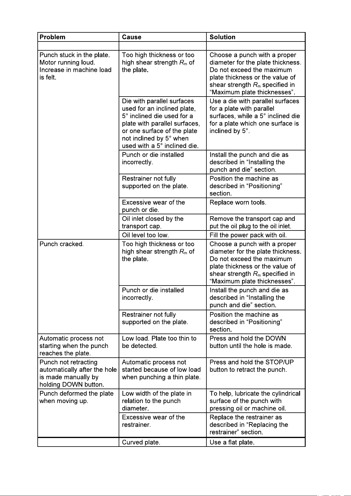
3.7. Troubleshooting
21
Page 22
22
Page 23

ACCESSORIES
5° INCLINED ROUND DIE
TO SUIT HOLEMAKER
PRO 60 HP & PRO 110 HP
Size Die Part No.
9mm HPRD09A
10mm HPRD10A
11mm HPRD11A
12mm HPRD12A
13mm HPRD13A
14mm HPRD14A
15mm HPRD15A
16mm HPRD16A
17mm HPRD17A
18mm HPRD18A
19mm HPRD19A
20mm HPRD20A
21mm HPRD21A
22mm HPRD22A
23mm HPRD23A
24mm HPRD24A
25mm HPRD25A
26mm HPRD26A
27mm HPRD27A
OBLONG PUNCH & DIE
TO SUIT HOLEMAKER
PRO 60 HP & PRO 110 HP
ROUND PUNCH & DIE
TO SUIT HOLEMAKER
PRO 60 HP & PRO 110 HP
Size Punch Part No. Die Part No.
7mm HPRP07 HPRD07
8mm HPRP08 HPRD08
9mm HPRP09 HPRD09
10mm HPRP10 HPRD10
11mm HPRP11 HPRD11
12mm HPRP12 HPRD12
13mm HPRP13 HPRD13
14mm HPRP14 HPRD14
15mm HPPR15 HPRD15
16mm HPRP16 HPRD16
17mm HPPR17 HPRD17
18mm HPRP18 HPRD18
19mm HPPR19 HPRD19
20mm HPPR20 HPRD20
21mm HPPR21 HPRD21
22mm HPRP22 HPRD22
23mm HPPR23 HPRD23
24mm HPPR24 HPRD24
25mm HPPR25 HPRD25
26mm HPPR26 HPRD26
27mm HPPR27 HPRD27
Size Punch Part No. Die Part No.
16 x 8mm HPOP1608 HPOD1608
18 x 9mm HPOP1809 HPOD1809
18 x 11mm HPOP1811 HPOD1811
20 x 10mm HPOP2010 HPOD2010
20 x 12mm HPOP2012 HPOD2012
20 x 14mm HPOP2014 HPOD2014
22 x 11mm HPOP2211 HPOD2211
22 x 14mm HPOP2214 HPOD2214
24 x 12mm HPOP2412 HPOD2412
25 x 9mm HPOP2509 HPOD2509
25 x 12mm HPOP2512 HPOD2512
25 x 13mm HPOP2513 HPOD2513
25 x 14mm HPOP2514 HPOD2514
25 x 18mm HPOP2518 HPOD2518
23
Page 24
ACCESSORIES
4.2. Balancer
Allows suspending the machine, balancing its weight,
and lifting/lowering the machine.
Part number:
M7-SP3220 (PRO 60 HP)
M7-SP3400 (PRO 110 HP)
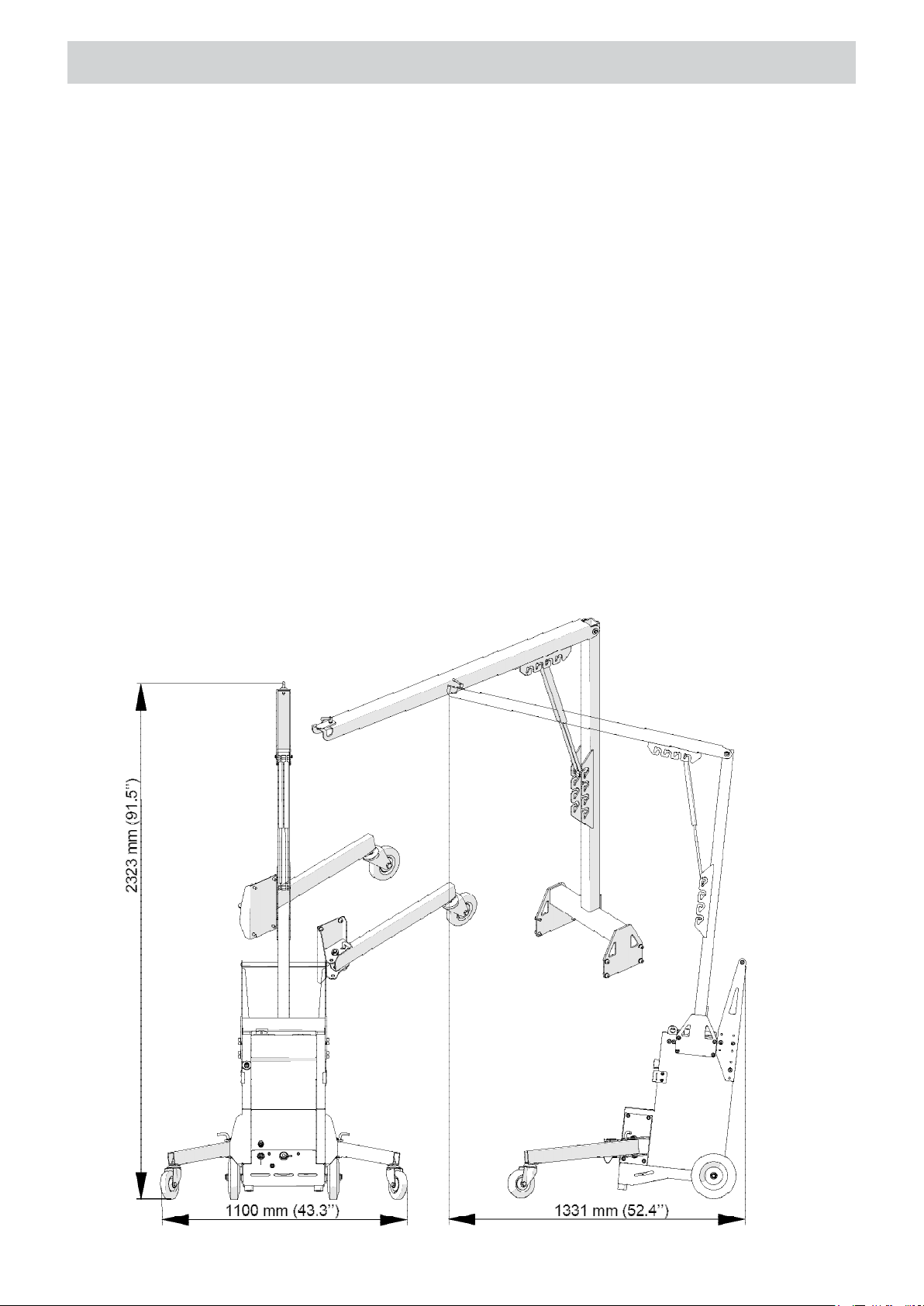
4.3. Crane
Allows suspending the machine, balancing its weight, and moving the machine along with the
power pack.
Part number:
WAD-HPP1010
24
Page 25
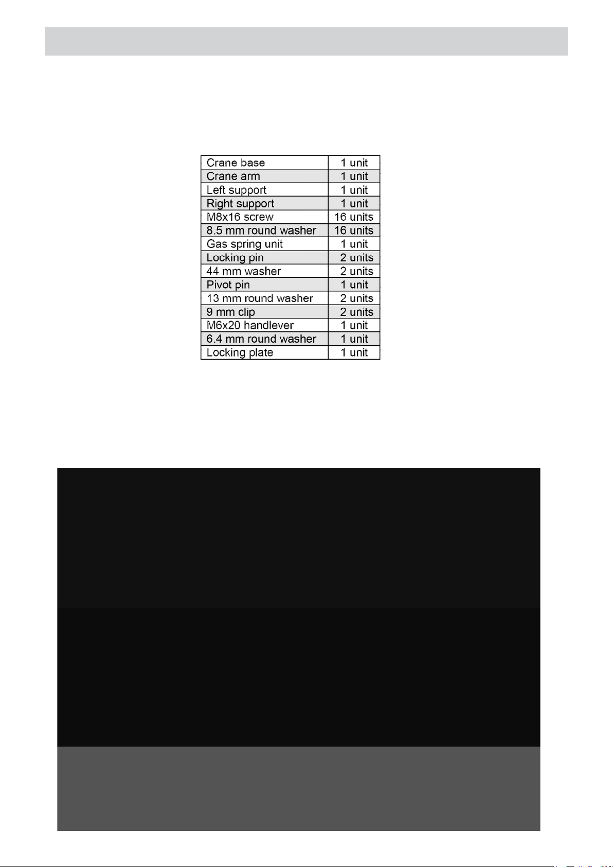
The included equipment consists of:
ACCESSORIES
To mount, screw the crane base into top holes on both power pack sides with eight
M8x16 screws and 8.5 mm washers (1, Fig. 11) using the 6 mm hex wrench. Use next eight
M8x16 screws and 8.5 mm washers (2) to screw the supports with the locking pins placed as
shown in detail 3 into lower holes on both sides of the power pack. Then, remove the pins,
slightly tilt the power pack backwards, and rotate the supports according to the arrow direction 4
to rest the power pack on the wheels.
25
Page 26
ACCESSORIES
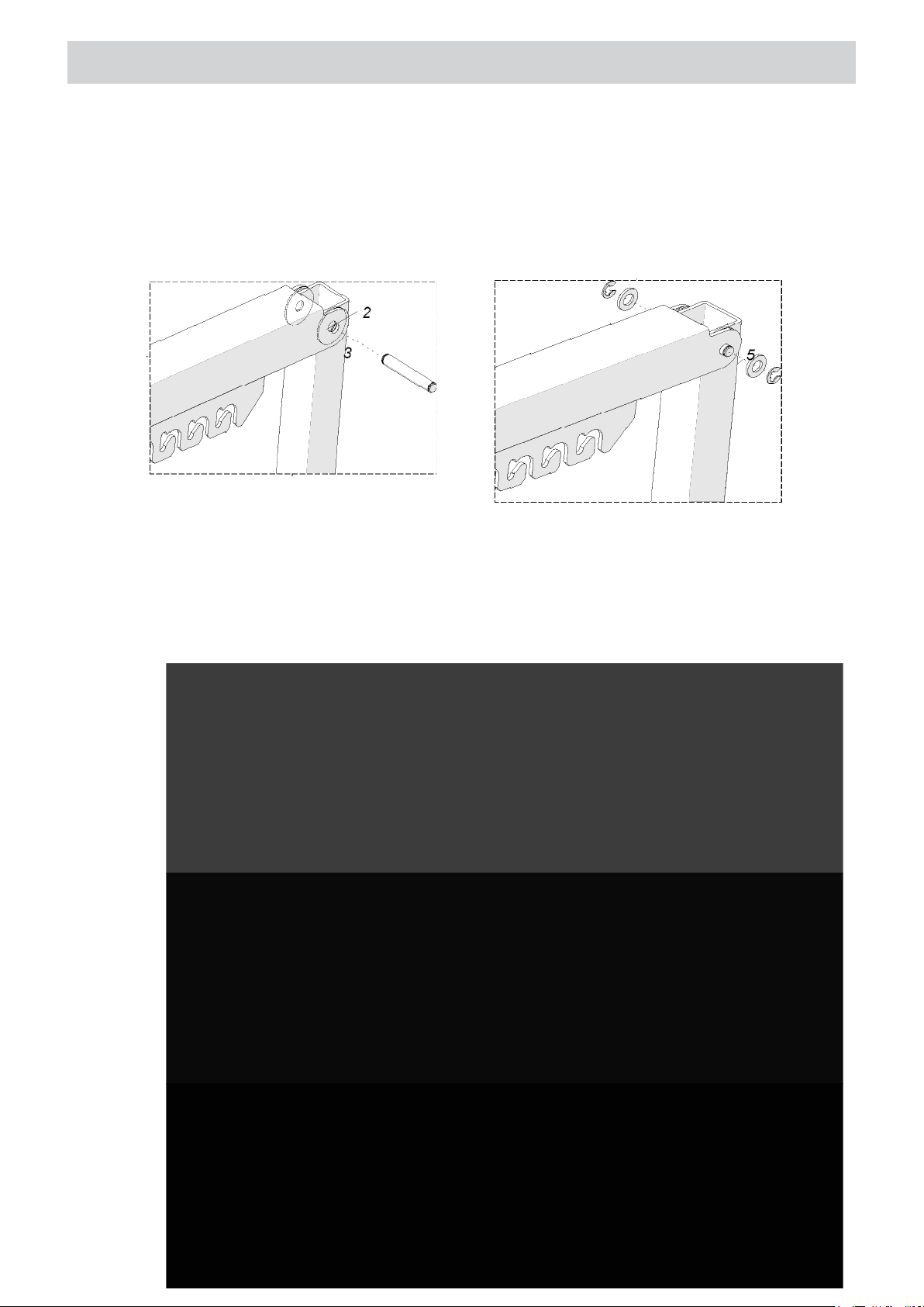
Lock the supports in this position by placing the pins in location 1 from Fig. 12. To join the
crane arm to the crane base, put two 44 mm washers (2) between the base and arm, and insert
the pivot pin (3). Next, at both sides put 13 mm round washers (4), and place the 9 mm clips (5)
into the grooves of the pivot pin.
Then, mount the gas spring unit between the crane arm and the crane base as shown in Fig.
13. Place the unit in a proper arm socket (1) to set such a force that will balance the weight of
the machine. Insert the piston rod into the base socket on the required height (2). Hang the
machine with the chain on the arm end (3), and lock the chain with the locking plate (4), 6.4 mm
washer (5), and M6x20 handlever (6). To set a diff erent force or height, remove the machine
with the chain and locate the gas spring unit in an adjacent socket of either comb 1 or 2.
26
Page 27

ACCESSORIES
27
Page 28

ACCESSORIES
4.4. Stationary work set
Allows operating the machine in a stationary position. The dual foot switch functions as the
STOP/UP and DOWN machine buttons to allow the punch to stop, raise, and lower.
Part number:
WAD-HPP1020
To mount the set, position the machine upside down and attach the support with two M8x20
screws and two 8.5 mm washers using the 6 mm hex wrench (Fig. 14).
28
Page 29

ACCESSORIES
Position the machine the right way up and rotate the restrainer in the direction shown in the
Fig. 15 to position the restrainer 2 mm (0.08’’) above the plate. Then, unscrew the front handle
and use it to tighten the guard in such a way to level the lower edge of the guard opening with
the machine edge indicated in the fi gure.
Plug the machine control connector into the female socket and connect the control cable
to the male socket of the foot switch junction box (Fig. 16).
29
Page 30
ACCESSORIES
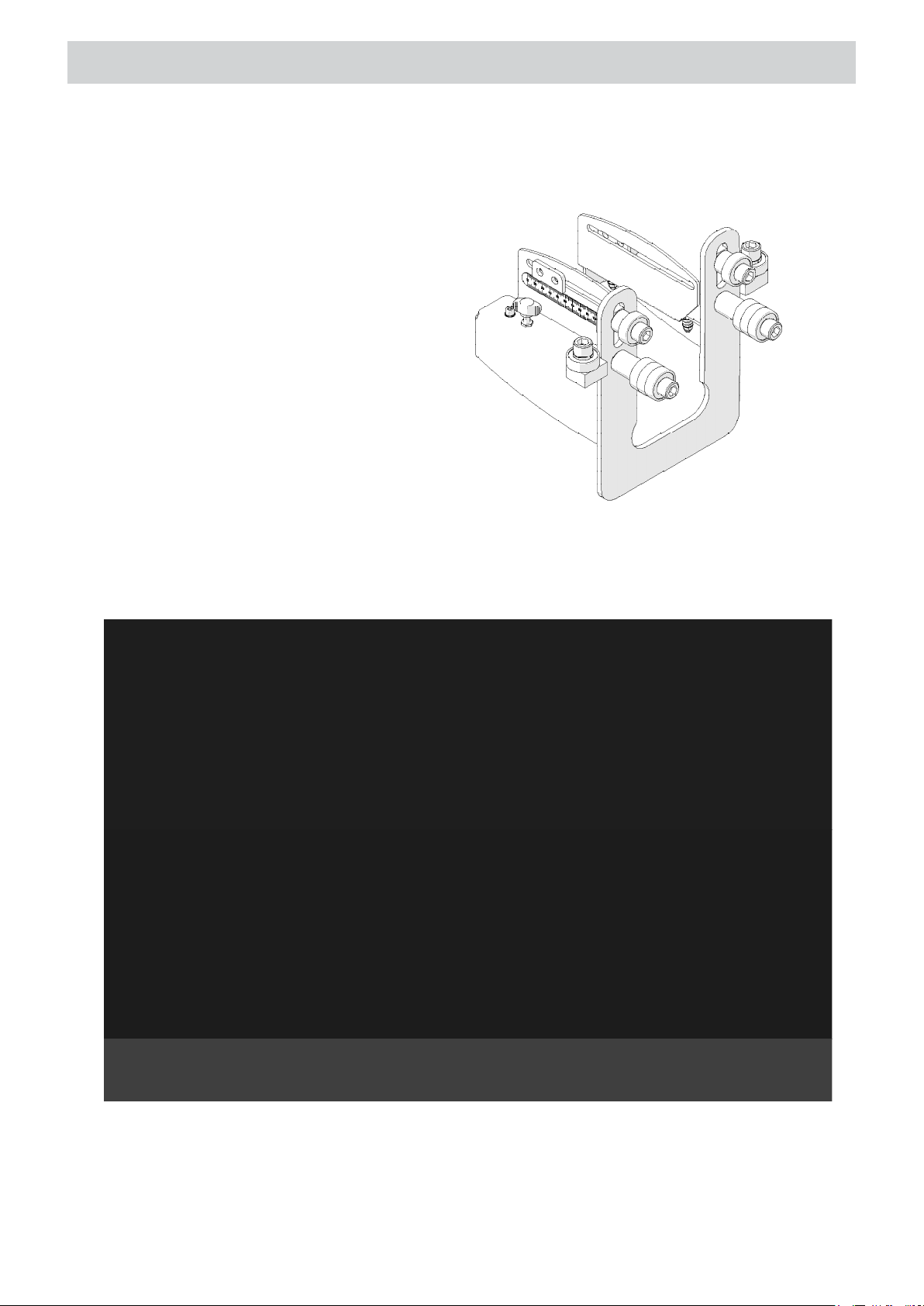
4.5. Guide
Allows guiding the machine along the workpiece.
Part number (for PRO 110 HP):
WAD-HPP1030
(two special washers included)
Dismount the depth stop by unscrewing four screws using the 6 mm hex wrench. Then, position
the machine on the plate and use DOWN button to slightly penetrate into a previously centerpunched mark on the plate (1, Fig. 17). Use the wrench to facilitate lowering the restrainer as far
as possible (2), which will press the plate to the die (3).
Loosen the wing screws (1, Fig. 18) fully and use the 10 mm hex wrench to loosen the upper
bearings 2. Next, position the guide on the machine in such a way to bring the lower, upper, and
side bearings in close contact with the plate (3). Tighten the upper bearings in this position.
30
Page 31

ACCESSORIES
Attach the guide to the machine with M8x16 screws and washers (4) using the 6 mm hex
wrench, then tighten the wing screws 1 to press the die to the plate. Next, raise the restrainer
(6) to position it 2 mm (0.08’’) above the plate (7).
Retract the punch from the plate and move the machine to the next center--punched
mark. If the mark is at a diff erent distance from the plate face than the mark of the base hole
is, loosen four M8x16 screws (4), adjust the position of the guide and tighten the screws in this
new position.
The machine with the mounted guide and positioned on a plate must always be held with
both hands. During moving the machine in direction 8, press the machine against the face of the
plate.
31
Page 32
ACCESSORIES
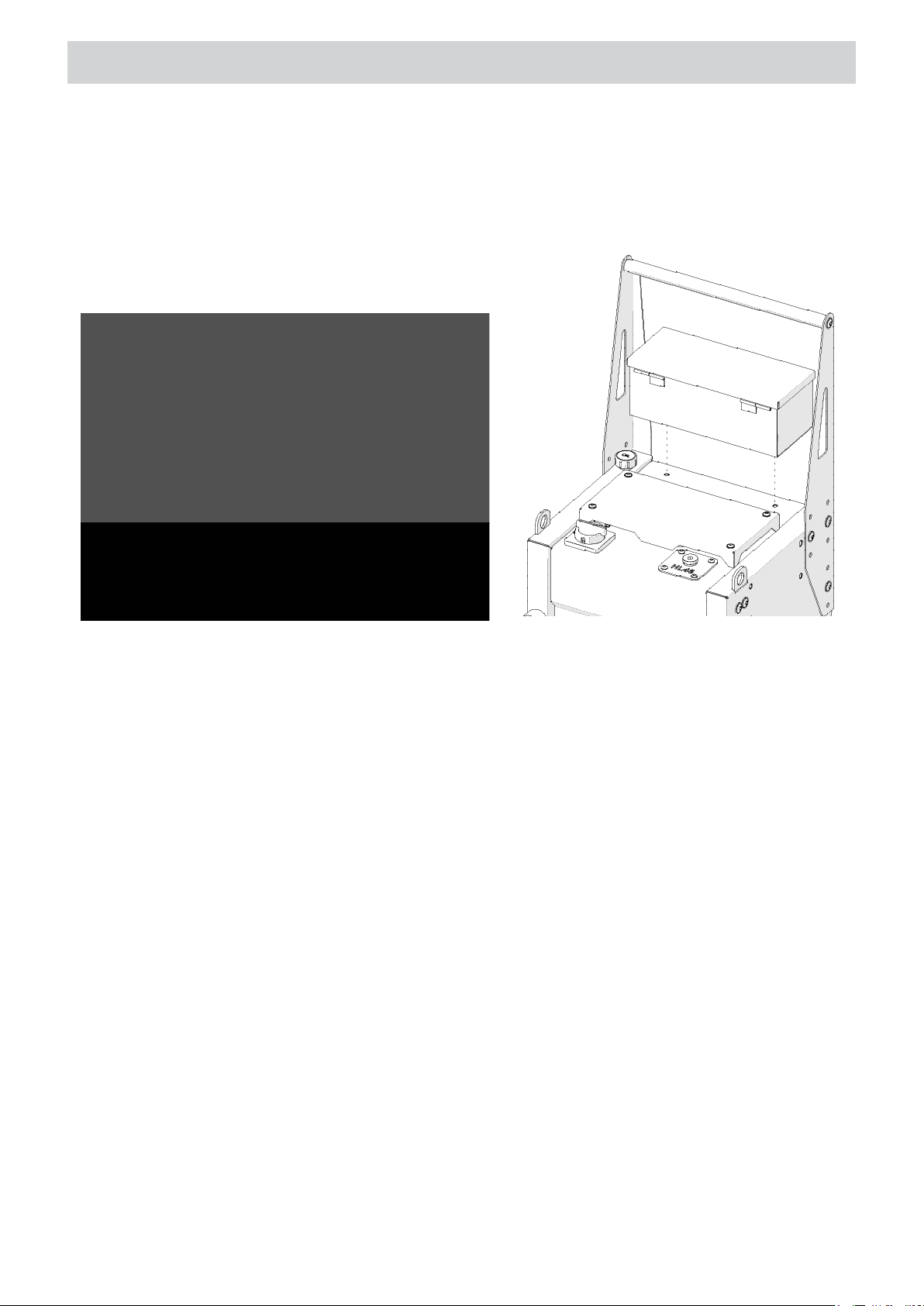
4.6. Tool box
Designed for storing tools. Mount on the power pack with two M6x12 screws using the 4 mm
hex wrench.
Part number:
WAD-HPP1040
(two M6x12 screws included)
32
Page 33
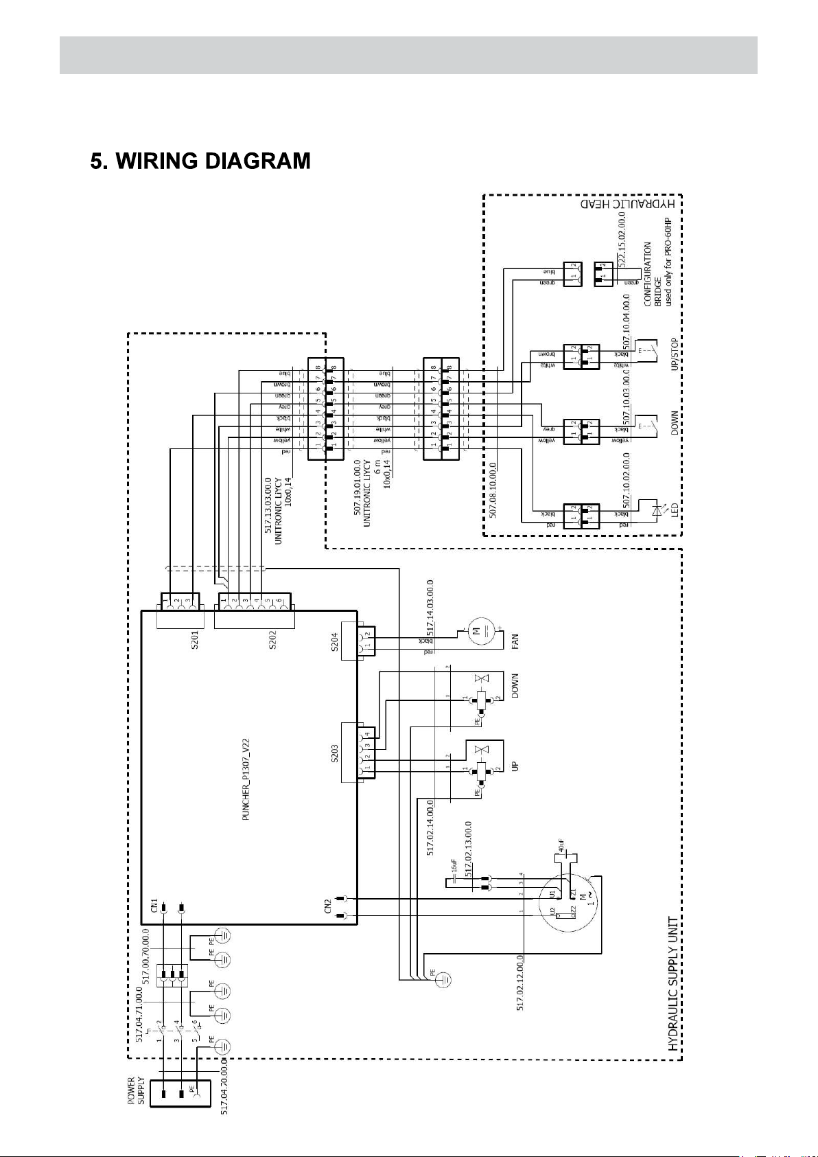
WIRING DIAGRAM
33
Page 34

PARTS LIST PRO 60 HP
34
Page 35

PARTS LIST PRO 60 HP
35
Page 36

PARTS LIST PRO 60 HP
36
Page 37

PARTS LIST PRO 60 HP
37
Page 38

PARTS LIST PRO 110 HP
38
Page 39

PARTS LIST PRO 110 HP
39
Page 40

PARTS LIST PRO 110 HP
40
Page 41

PARTS LIST PRO 110 HP
41
Page 42

PARTS LIST HPP 700
42
Page 43

PARTS LIST HPP 700
43
Page 44

PARTS LIST HPP 700
44
Page 45

PARTS LIST HPP 700
45
 Loading...