

Page 1
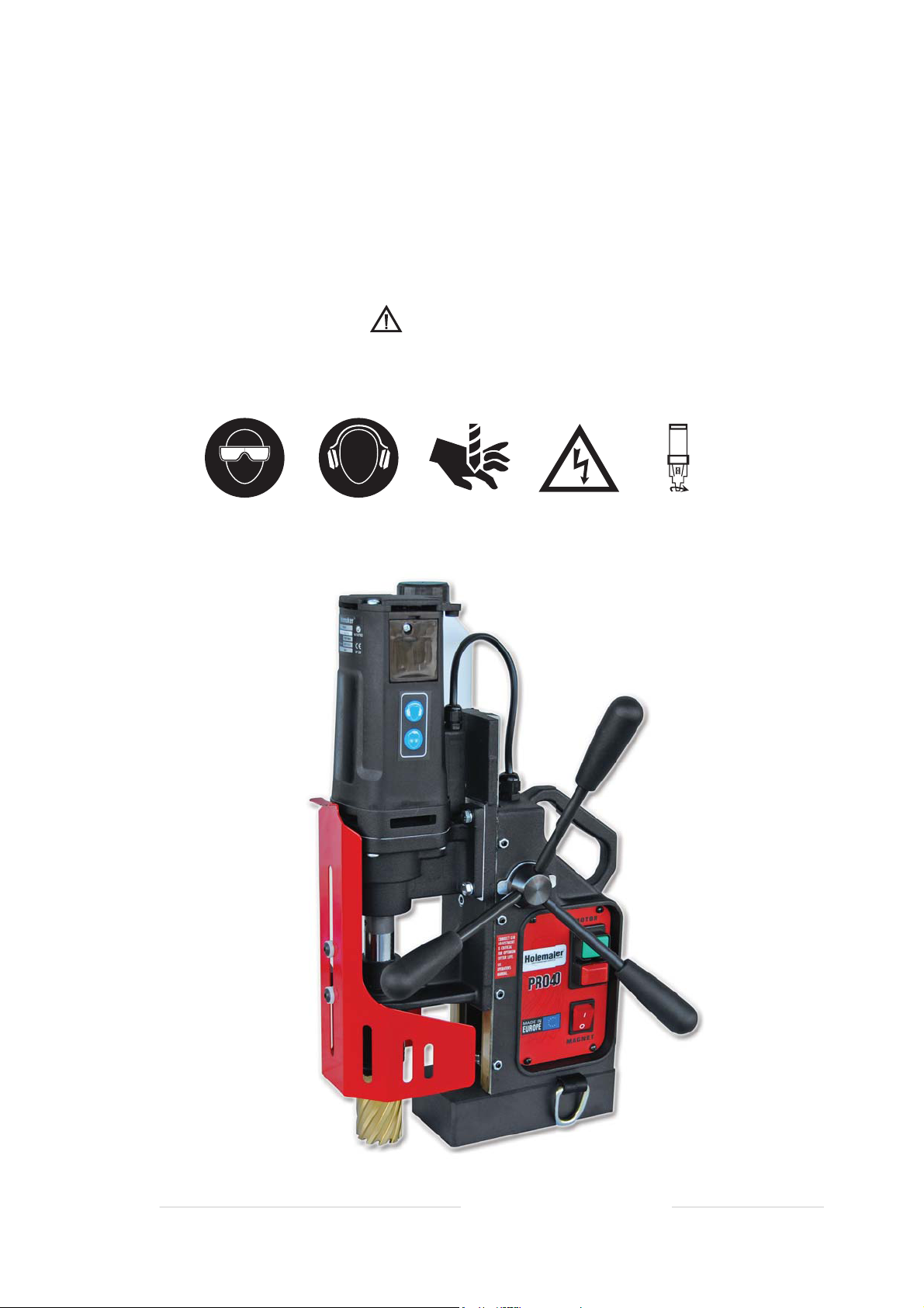
HOLEMAKER PRO 40
Holemaker Portable Magnetic Drilling Machine
OPERATOR’S MANUAL
WARNING!
BEFORE USE, ENSURE EVERYONE USING THIS MACHINE READS AND UNDERSTANDS
ALL SAFETY AND OPERATING INSTRUCTIONS IN THIS MANUAL .
EYE P ROTECTION
REQUI RED
HEARI NG PRO TECTION
REQUI RED
NEVER PLACE
FINGE RS NEA R
CUTTI NG ARE A OR
MACHI NE ARB OR
LINE VOLTAG E
PRESE NT
BEWAR E OF
ROTAT ING
MACHI NE PAR TS
esahcruP fo etaD # laireS
Page 2

Holemaker PRO 40 Portable Magnetic Drilling Machine
Congratulations on the purchase of your Holemaker Pro 40 portable magnetic drilling machine.
Holemaker drilling machines are designed to deliver fast, efficient hole drilling performance in portable applications.
TABLE OF CONTENTS
Important Safety Instructions . . . . . . . . . . . . . . . . . . . . . . . . . . . . . . . . . . .3 -4
Power Supply Requirement . . . . . . . . . . . . . . . . . . . . . . . . . . . . . . . . . . . . . .5
Technical Data . . . . . . . . . . . . . . . . . . . . . . . . . . . . . . . . . . . . . . . . . . . . . . . . . 6
Special Instructions . . . . . . . . . . . . . . . . . . . . . . . . . . . . . . . . . . . . . . . . . . . .7
Before You Drill . . . . . . . . . . . . . . . . . . . . . . . . . . . . . . . . . . . . . . . . . . . . . . . .7
Machine Operation . . . . . . . . . . . . . . . . . . . . . . . . . . . . . . . . . . . . . . . . . .8-10
Maintenance and Service . . . . . . . . . . . . . . . . . . . . . . . . . . . . . . . . . . . . . . .11
Basic Troubleshooting . . . . . . . . . . . . . . . . . . . . . . . . . . . . . . . . . . . . . . . . .12
Machine Parts Breakdown. . . . . . . . . . . . . . . . . . . . . . . . . . . . . . . . . . . 13 - 22
Electrical Diagram . . . . . . . . . . . . . . . . . . . . . . . . . . . . . . . . . . . . . . . . . . . 23
LIMITED WARRANTY
Industrial Tool & Machinery Sales (hereinafter refered to as ITMS) will, within twelve (12) months from the
original date of purchase, repair or replace any goods found to be defective in materials or workmanship.
This warranty is void if the item has been damaged by accident, neglect, improper service or other causes
not arising out of defects in materials or workmanship.
This warranty does not apply to machines and/or components which have been altered, changed, or
modified in any way, or subjected to overloading or use beyond recommended capacities and specifications.
Worn componentry due to normal wear and tear is not a warranty claim.
Goods returned defective shall be returned prepaid freight to ITMS or agreed repair agent, which shall be
the buyer’s sole and exclusive remedy for defective goods. ITMS accepts no additional liability pursuant to
this guarantee for the costs of travelling or transportation of the product or parts to and from ITMS or the
service agent or dealer, such costs are not included in this warranty.
Our goods come with guarantees which cannot be excluded under the Australian Consumer Law.
You are entitled to replacement or refund for a major failure and to compensation for other reasonably
foreseeable loss or damage. You are also entitled to have the goods repaired or replaced if the goods
fail to be of acceptable quality and the failure does not amount to a major failure.
THE MANUFACTURER RESERVES THE RIGHT TO MAKE
IMPROVEMENTS AND MODIFICATIONS TO DESIGN WITHOUT PRIOR NOTICE.
Imported And Distributed By
INDUSTRIAL TOOL & MACHINERY SALES
18 BUSINESS ST, YATALA, QLD AUSTRALIA 4207
PHONE 07 3287 1114 FAX 07 3287 1115
[email protected] www.industrialtool.com.au
2
Page 3

IMPORTANT SAFETY INSTRUCTIONS
WARNING!
WHEN USING ELECTRICAL TOOLS,BASIC SAFETY PRECAUTIONS SHOULD ALWAYS BE FOLLOWED
TO REDUCE RISK OF FIRE
READ AND SAVE ALL INSTRUCTIONS FOR FUTURE REFERENCE.
1. Keep Work Area Clean
• Cluttered areas and benches increase risk of injuries.
2. Consider Work Area Environment
• Do not expose power tools to rain.
• Do not use power tools in damp or wet locations.
• Keep work area well lit.
• Do not use tool in presence of flammable liquids or gases.
3. Guard Against Electric Shock
• Prevent body contact with grounded surfaces. For example: pipes, radiators, ranges and refrigerator enclosures.
, ELECTRIC SHOCK AND PERSONAL INJURY .
4. Keep Children Away
• Do not let visitors contact tool or extension cord.
• All visitors should be kept away from work area.
5. Store Idle Tools
• When not in use, tools should be stored in a dry, high and locked-up place, out of reach of children.
6. Do Not Force Tool
• It will do the job better and safer at the rate for which it was intended.
7. Use Right Tool
• Do not force a small tool or attachment to do the job of a heavy-duty tool.
• Do not use tool for unintended purpose. For example: Do not use a circular saw for cutting tree limbs or logs.
8. Dress Properly
• Do not wear loose clothing or jewellery. They can be caught in moving parts.
• Rubber gloves and non-skid footwear are recommended when working outdoors.
• Wear protective hair covering to contain long hair.
• Always wear safety glasses
• Use face or dust mask if necessary
• Use hearing protection
9. Do Not Abuse Electrical Cord
• Never carry tool by cord or yank it to disconnect from receptacle.
• Keep cord away from heat, oil and sharp edges.
10. Secure Work
• Use clamps or a vise to hold work. It’s safer than using your hand and it frees both hands to operate tool.
11. Do Not Overreach
• Keep proper footing and balance at all times.
3
Page 4
IMPORTANT SAFETY INSTRUCTIONS
12. Maintain Tools With Care
• Keep tools sharp and clean for better and safer performance.
• Follow instructions for lubricating and changing accessories.
• Inspect tool cords periodically and if damaged, have repaired by authorized service facility.
• Inspect extension cords periodically and replace if damaged.
• Keep handles dry, clean, and free from oil and grease.
13. Disconnect Tools
• Unplug when not in use, before servicing, and when changing accessories, such as cutters.
14. Remove Adjusting Keys And Wrenches
• Form habit of checking to see that keys and adjusting wrenches are removed from tool before turning it on.
15. Avoid Unintentional Starting
• Do not carry a plugged-in tool. Always disconnect from power source before moving.
• Be sure switches are off before connecting to a power source.
16. Outdoor Use Of Extension Cords
• When tool is used outdoors, use only extension cords intended for use outdoors and so marked.
17. Stay Alert
• Watch
• Do not use when taking medications that may cause drowsiness.
what you are doing. Use common sense. Do not operate tool when you are tired.
18. Check Damaged Parts
• Before further use of the tool, any damaged parts should be repaired and performance verified prior to operation.
• Check alignment of moving parts, binding of parts, breakage of parts, mounting, and any other conditions
that may affect its operation. Any part that is damaged should be properly repaired or replaced
by an authorized service center.
• Do not use this tool if switches do not turn it on and off. Have defective switches replaced by authorized
service center.
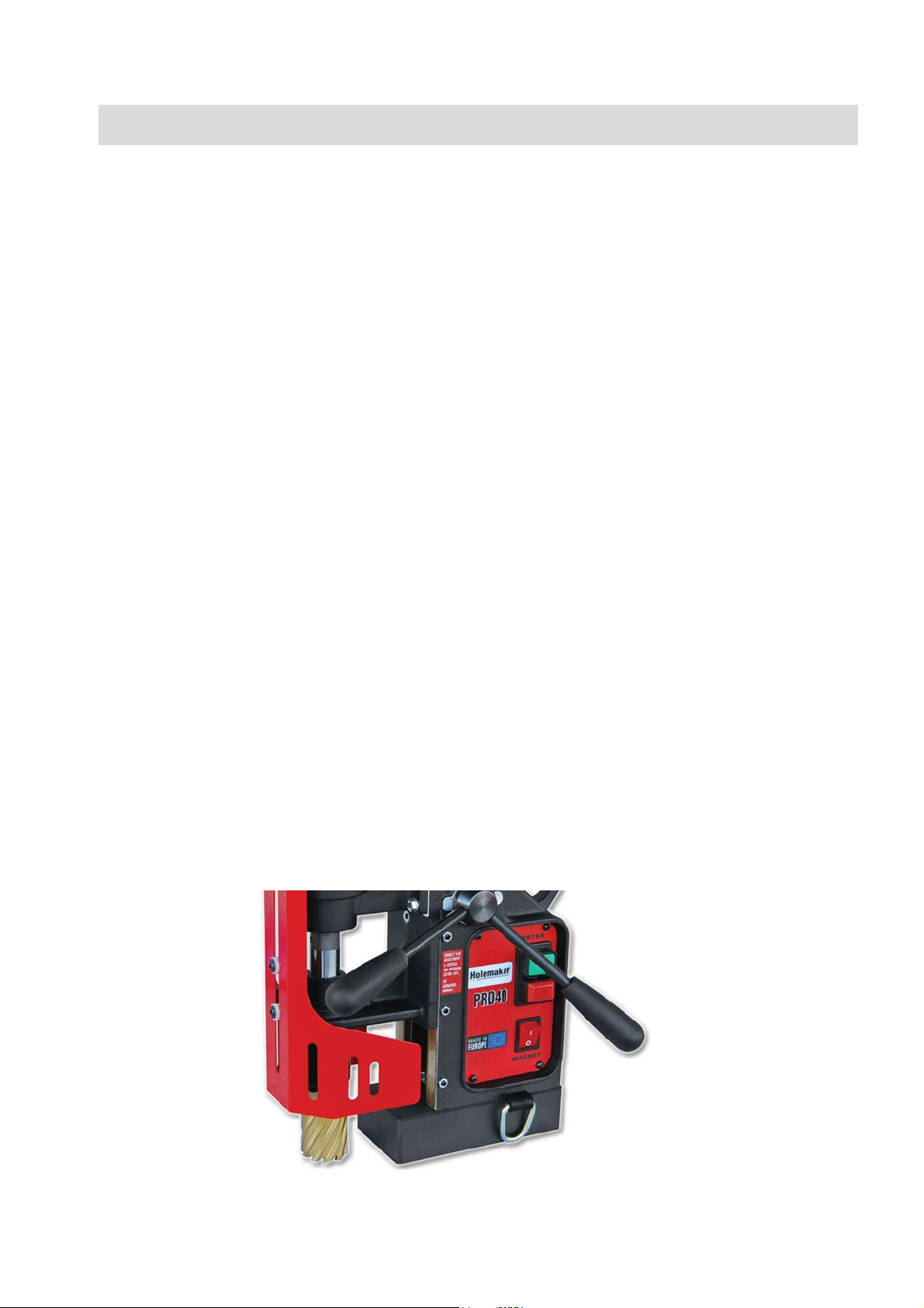
19. Use Cutter Guard
Always use cutter guard supplied with machine to reduce the risk of injury. (refer fig. 1)
•
Fig. 1
4
Page 5
POWER SUPPLY REQUIREMENTS
Prior to use check condition of the power cord, which has to be free of any cuts, or similar damages.
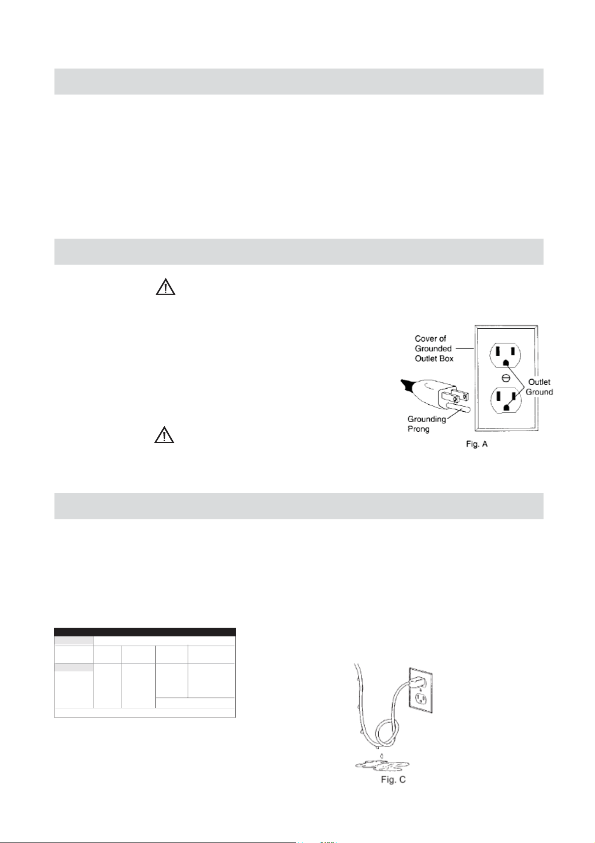
Attention!: This unit has a class one of insulation and
absolutely requires the power source
to be equipped with a protection circuit.
Power source should be protected with the difference-current circuit cut-out and protected with a 10A fuse - for 230V.
At building sites, power should be supplied from a separation transformer such as Type AVM, with minimum power of
2000 VA and with second class protection.
GROUNDING INSTRUCTIONS
WARNING!
Improperly connecting the grounding wire can result in the risk of electrical shock.
Check with a qualified electrician if you are in doubt as to whether the outlet
is properly grounded. Do not modify the plug provided with tool. Never remove
the grounding prong from the plug. If the cord or plug is damaged, have it
repaired before using. If the plug will not fit the outlet, have a proper outlet
installed by a qualified electrician. The Holemaker must be plugged into an
appropriate outlet, properly installed and grounded in accordance with all codes
and ordinances. The plug and outlet should look similar to those in Figure A.
If in doubt of proper grounding, call a qualified electrician.
WARNING!
DO NOT USE HOLEMAKER DRILLING MACHINES ON SURFACES OR MATERIALS BEING
WELDED
. DOING SO CAN RESULT IN DAMAGE TO THE DRILLING MACHINE.
EXTENSION CORDS
Use only 3-wire extension cords that have 3-prong grounding-type plugs and 3-pole receptacles that accept the
tool’s plug. Replace or repair damaged cords. Make sure your extension cord is in good condition. When using
an extension cord, be sure to use one heavy enough to carry the current your product will draw. An undersized cord
will cause a drop in line voltage resulting in loss of power and overheating. See table for the correct size to use
depending on cord
gauge number, the heavier the cord.
VOLTS
240V
AMPERAGE
0-6
6-10
10-12
12-16
MINIMUM GAUGE FOR EXTENSION CORDS
TOTAL LENGTH OF CORD IN METRES
0 - 15 15 - 30 30 - 60 60 - 90
18 16 16 14
18 16 14 12
16 16 14 12
14
12
RECOMMENDED WIRE GAUGE
and nameplate amperage rating. If in doubt, use the next heavier gauge. The smaller the
length
DRIP LOOP: To help prevent cutting fluids from traveling
along power cord and contacting power source, tie a drip
loop in power cord as shown in Figure C.
NOT RECOMMENDED
5
Page 6
TECHNICAL DATA
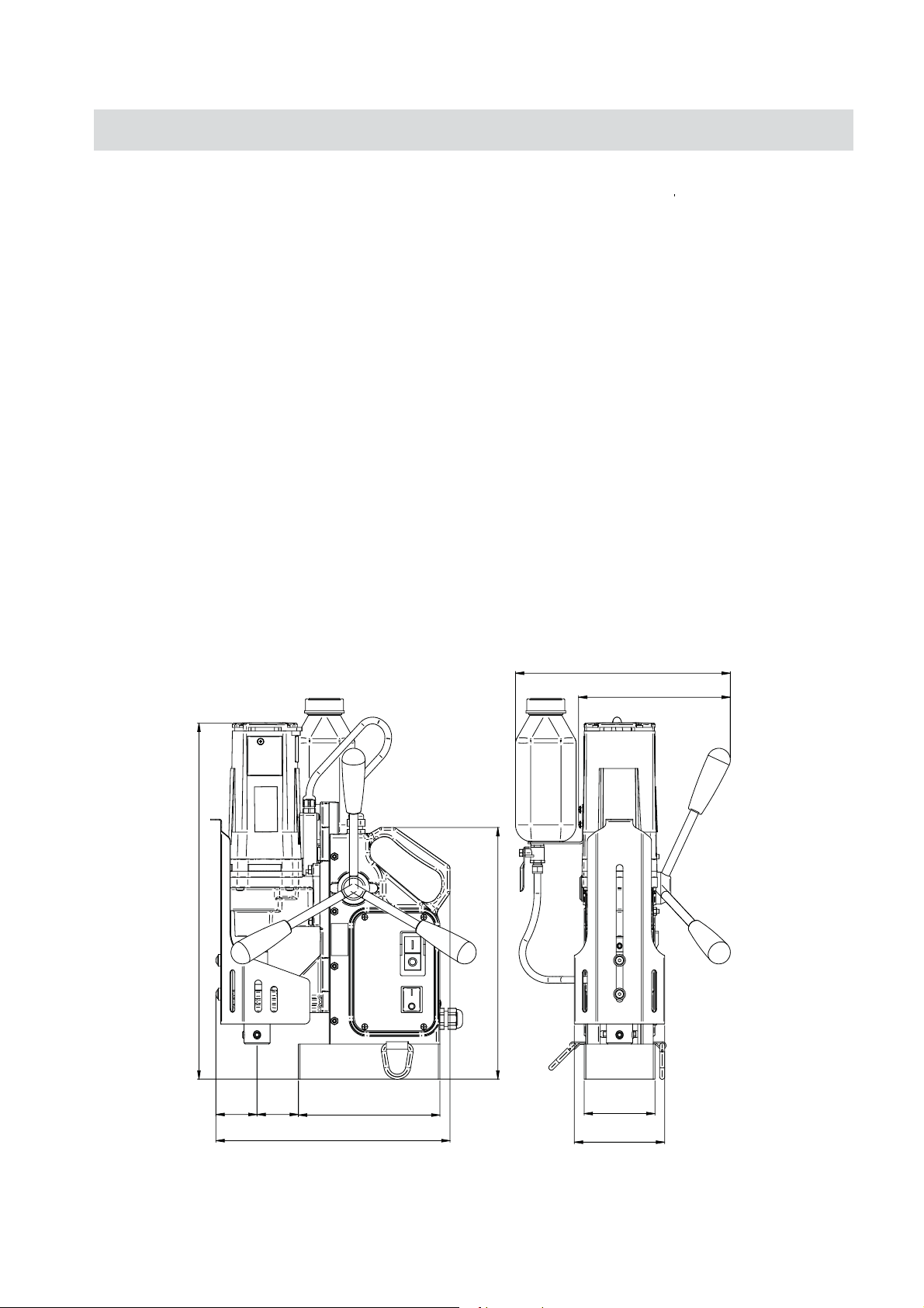
Supply voltage: ………………………………… 220-240V/ 50-60 Hz.
Motor power ……………………………………………………. 1020 W
Total power …………………………………………………….. 1100 W
Machine speeds (under load): ………………....................... 440rpm
Insulation class ………………………………………………….. First
3
Tool holder …………………………………. (
Capacities: max. holemaker cutter diameter …………............. 40mm
max. drilling depth with standard arbor ………...... 52mm
Magnet Dead Lift (on 25 mm plate) ………......................... 10650 N
Dimensions:
electromagnetic base …...................................... 84x168x41.5 mm
Length of the power cord ……………………............................. 3 m
Total weight ………………………………...…...................... 12.5 kg
Noise level ……………………………………………...……....... 85 dB
/4" Weldon) 19.05 mm
385 - 509 mm
49mm49
mm
168mm
278mm
255mm
180mm
298mm
84mm
107mm
6
Page 7

SPECIAL INSTRUCTIONS
1. Read and follow operator’s manual thoroughly.
2. DO NOT touch rotating cutter or parts.
3. Always stop machine completely and unplug from power source before changing cutters, clearing swarf,
refilling lubrication or performing adjustments.
4. Never wear loose clothing or gloves when working near cutting area or machine arbor.
5. Always wear eye protection. Any tool can shatter.
6. Always use safety chain or strap provided with machine.
7. Always use proper tooling. Keep cutters securely fastened.
8. DO NOT use dull or broken cutters.
9. Beware of ejected slugs at end of cut. They become HOT during the cut.
10. Keep all safety features functioning and working properly.
11. Keep bottom of magnet burr free and clear of chips and debris.
12. To reduce the risk of electrical shock, DO NOT remove or alter electrical panels or use machine in damp
areas.
13. Use only authorized service centers for repairs.
WHAT YOU SHOULD KNOW BEFORE YOU DRILL
1. Type of material to be drilled, Brinnell or Rockwell hardness, material thickness and position should all be
determined to ensure proper selection of cutting tools.
2. Remove any excessive mill scale or rust from surface to be drilled.
3. When drilling thin materials,
magnet area to increase magnetic holding force.
4. Material that has been flame cut may become heat treated and therefore difficult to drill. Avoid drilling near such
areas whenever possible.
5. Special cutter lubricant is available for using the Holemaker and annular cutters in the horizontal
position. Consult you distributor for more information.
Caution: Do not drill on material where welding is also simultaneously being performed. Drilling machine will
be damaged.
Caution: Powering drilling machine from generator without proper surge protection device between
generator
The Holemaker Pro 40 is not designed for use on steel thinner than 3/8” or 10mm, as the magnet’s adhesive
power would be significantly reduced which can cause machines failure or individuals injury.
The machines built in “Smart Magnet Technology” will detect insufficient magnetic adhesion, and will
cause the machines motor on/off button to not engage. Although it is not recommended, this feature can
be bypassed by following the attached “Smart Magnet Technology Bypass” instruction leaflet.
and drilling machine may cause damage to the Printed Circuit Board in machine.
recommend
it is
ed that you
place a steel plate under the work piece and Holemaker
7
Page 8
MACHINE OPERATION (BEFORE YOU CUT)
Remove all contents from packaging and inspect to ensure no damage was incurred during shipping.
Your Holemaker package should include the following:
QTYDESCRIPTION
HOLEMAKER PRO40 MACHINE
METAL CARRY CASE
SAFETY CHAIN WITH CLIP
HEX WRENCH 2.5mm
HEX WRENCH 3mm
HEX WRENCH 4mm
SPANNER 8mm
SPOKE HANDLE WITH KNOBS
COOLANT BOTTLE ASSEMBLY
OPERATORS MANUAL
SMART MAGNET BYPASS
1
1
1
1
1
1
1
3
1
1
1
CAUTION!
BE SURE YOUR HOLEMAKER MACHINE IS DISCONNECTED FROM THE POWER SOURCE BEFORE MAKING ADJUSTMENTS .
1. Assemble 3 spoke handles to the Holemaker pinion hub. NOTE: Pinion assembly is mounted on the right
side of the machine frame. If necessary, it can be reversed to operate from the left side of the frame.
Simply remove the screw from the left edge of the pinion. Remove pinion from the right side of the frame
and insert it in to the left side of the frame. Replace flat washer and screw (tighten securely).
2. To install coolant bottle, use bracket to slide coolant bottle onto the two retaining screws, located on the right
side of the drill. Install the hose connector in to the hose fitting on the side of the coolant ring.
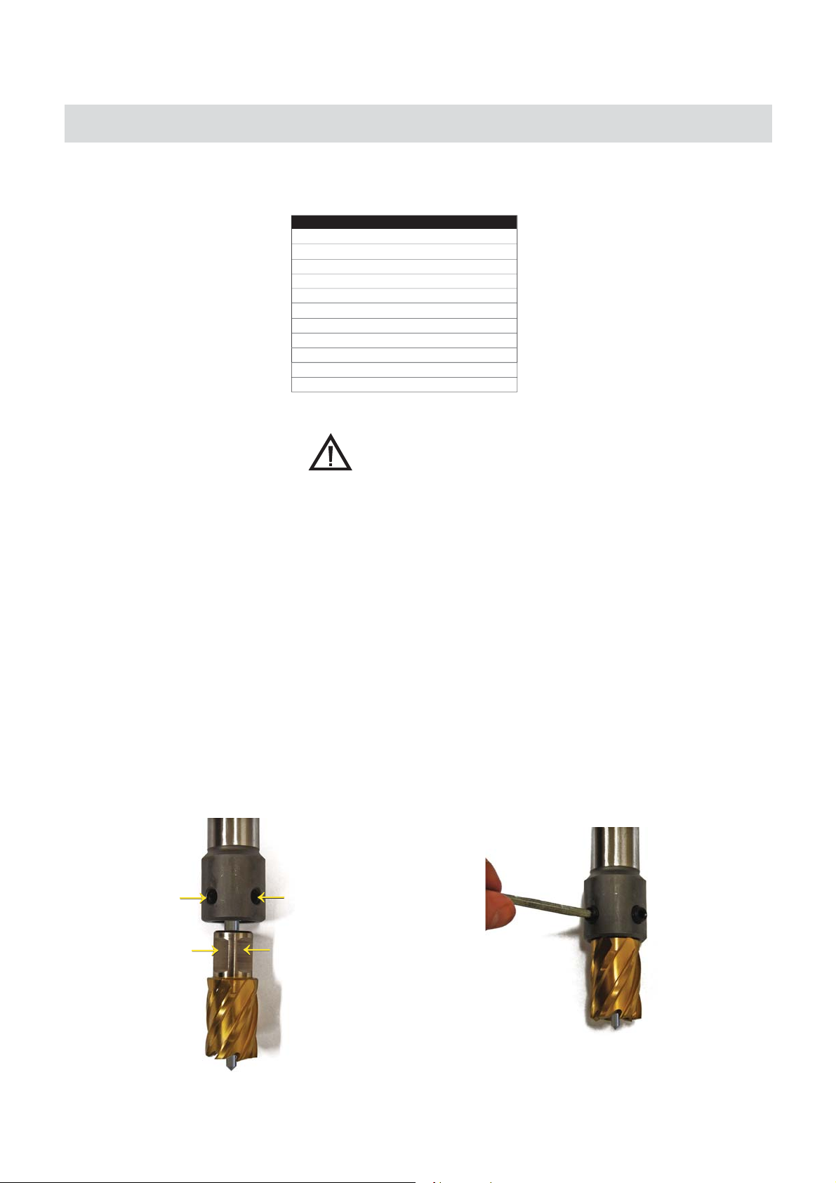
3. USING GRUB SCREW ARBOR SYSTEM
(The Holemaker PRO 40 is also available with either a standard grub screw, or a quick grip arbor system)
a. Place the Pilot Pin into the cutter as seen below.
b. Loosen the grub screws
with the hex key provided & align the two flat sections
of the cutter shank with the grub screws.
c. Insert the cutter shank completely into the arbor.
Retighten both grub screws, clamping the flat
sections of the shank & locking the cutter into
place.
8
Page 9
MACHINE OPERATION (BEFORE YOU CUT)
OPERATING INSTRUCTIONS (BEFORE YOU CUT)
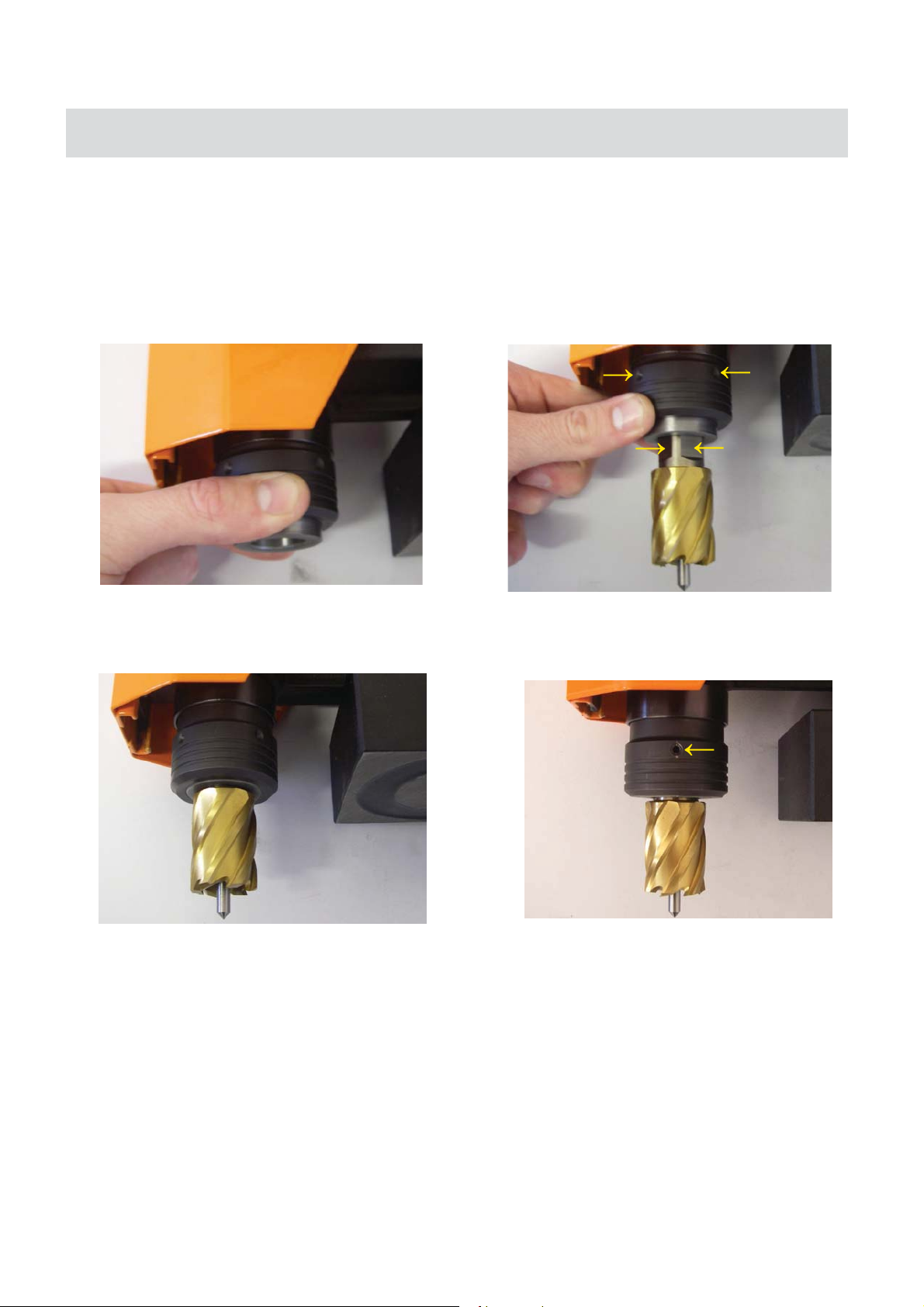
4. USING QUICK GRIB ARBOR SYSTEM
(The Holemaker PRO 40 is also available with either a standard grub screw, or a quick grip arbor system)
Place the Pilot Pin into the cutter as seen below.
b.a.The Holemaker pro 40 uses a quick release arbor
system which accepts standard Holemaker Cutters
by locking onto one flat section of the cutter.
Alternate brand cutters may not be suitable.
b.
.d The annular cutter is now secured into the arbor
and ready for use. To remove the cutter from the
arbor, repeat this action in reverse.
d.
c. Align the two flat sections of the cutter shank with
the two indents that are on the arbor collar. While
keeping the collar pushed upwards, slide the cutter
into the arbor,
c.
e.
DO NOT LOOSEN GRUB SCREW ON ARBOR COLLAR
NOTE: Ensure all setup steps are completed
(including the next page) prior to drilling.
e.
5. Fill coolant reservoir with Holemaker Water Soluble Cutting Fluid
9
Page 10

OPERATING INSTRUCTIONS (BEFORE YOU CUT)
1. Place the Holemaker PRO 40 on the work piece.
2. Attach the safety chain supplied between the machine and the workpiece
3. Lower cutter/drill to surface of material. When using cutter tool holder, coolant flow starts when pilot pin is
depressed. Lifting pilot pin off work surface will stop coolant flow.
4. Position the drilling machine with the pilot pin over the center of the hole to be cut.
5. Move the rocker switch located on the panel to the ON position. The switch will illuminate to indicate DC
power is going to the magnet.
6.
The Holemaker PRO 40 has a “smart” magnet feature fitted. This feature ensures the Holemaker PRO 40 will
not operate unless there is sufficient magnetic adhesion available. See “Basic Troubleshooting” for more
information. This feature can be bypassed if required. Please contact ITMS or your local dealer for details.
7.
Position chip guard toward material being drilled
8.
Depress motor ON switch to start drill.
To start a cut, apply pressure until the cutter has establised an external grove. Then apply steady pressure
9.
through the remainder of the cut (Note: Do not peck drill when using annular cutters). The tools are designed
to evacuate chips when drilling.
MACHINE OPERATION (MAKING THE CUT)
MACHINE OPERATION (AFTER THE CUT)
1. After the cut has finished, the slug should be expelled on the down stroke. If the slug is not expelled after the
cut, disconnect the machine from the power source and remove the cutter from the arbor body, then expel the
slug. (Caution: The pilot should not be used to do this).
2. After the cut is finished, return motor to the full upright position, depress motor OFF button and wait until
motor fully stops. Move magnet switch to the OFF position to release the magnetic base from the material.
INSTRUCTIONS TO CONVERT YOUR HOLEMAKER
PRO 40 TO ACCEPT TWIST DRILLS USING
OPTIONAL CHUCK & ADAPTOR PART# SA70102
1. Remove arbor, by unscrewing 2 hex screws, which connect the arbor to the motor.
2. Disconnect the arbor from the motor, and pull down through the support casting.
Also remove the coolant inducer.
3. Push the optional 13mm chuck and adaptor, up through the support casting, and tighten the 2
hex screws onto the flats of the motor spindle.
10
Page 11

REGULAR MAINTENANCE
The motor slide may become loose and require adjustment after the machine has been in use for the first
1.
few weeks. Loosen the 4 locking nuts ; bring the motor slide into the full down position. Using a hex key,
equally tighten 4 adjustment screws, working from the center frame position to top and bottom. Proper
adjustment would mean the 3-spoke handle controlling the motor slide should stay in whatever position you
bring it in to (no drifting down off the slide). When all 4 hex screws have been adjusted, tighten 4 locking
nuts to maintain adjustment. This adjustment should be required very infrequently because of the precision
of the machine.
2. The motor slides are made of brass; they should be protected from contamination and periodically
lubricated with good multi-purpose grease.
3. The motor slides and spring inserts should be inspected and replaced if they have become worn, or damaged
in any way.
4. Keep the magnet clean and free of chips, oil or other contaminants.
5. Inspect arbor, sleeve and support bracket for visible wear.
6. The cutting speed should be kept in such a way as not to cause any substantial decrease in motor speed.
7. Non-coolant cutting is not recommended, but if such a case occurs the co-acting parts of arbor should be
lubricated from time to time with good multi-purpose grease.
8. Inspect motor brushes and replace after extended periods of machine usage.
9. Replace any worn parts and tighten fasteners that become loose during daily usage.
11
Page 12

BASIC TROUBLESHOOTING
1. Magnetic base not holding securely
• Material is too thin.
• Surface of material being drilled must be free of chips, debris, rust and mill scale.
• Does size of cutter exceed machine’s rated capacity?
• Check magnet face for unevenness, nicks and burrs.
2. Drill motor running, arbor and spindle not turning
• Possible sheared drive train component.
3. Motor slows when drilling
• Is an extension cord being used? If so, see page 5 for recommended wire gages and cord lengths.
• Excessive downfeed pressure during drilling cycle will cause motor to slow and overheat.
• Does cutting tool need to be resharpened?
4. Coolant system not working
• Coolant system is gravity dependent, machine must be in a upright position to operate properly.
• Dirt or debris in coolant tank.
• Consistency of coolant mixture too thick.
• Is correct pilot pin being used?
• Vent hole in coolant tank lid blocked.
5. Slugs not ejecting from cutter
• Lack of coolant causing slugs to expand in cutter bore.
• Is correct pilot pin being used?
• Possible broken internal arbor parts.
6. Breaking cutters
• How is coolant being applied? Coolant must be supplied to interior of cutter.
• Excessive feed pressure being applied when cutter initially contacts work surface.
• Confirm material hardness.
• Drilling stacked materials with incorrect cutter.
• Dull cutters; dull or chipped cutting edges require excessive feed pressure, resulting in breakage.
••Movement of machine on material - See “1. Magnetic base not holding securely”
Inconsistent hardness in material can cause cutter breakage
7. Oversized or rough holes
• Insufficient coolant.
• Excessive feed pressure.
• Dull cutter.
12
Page 13
MACHINE BREAKDOWN
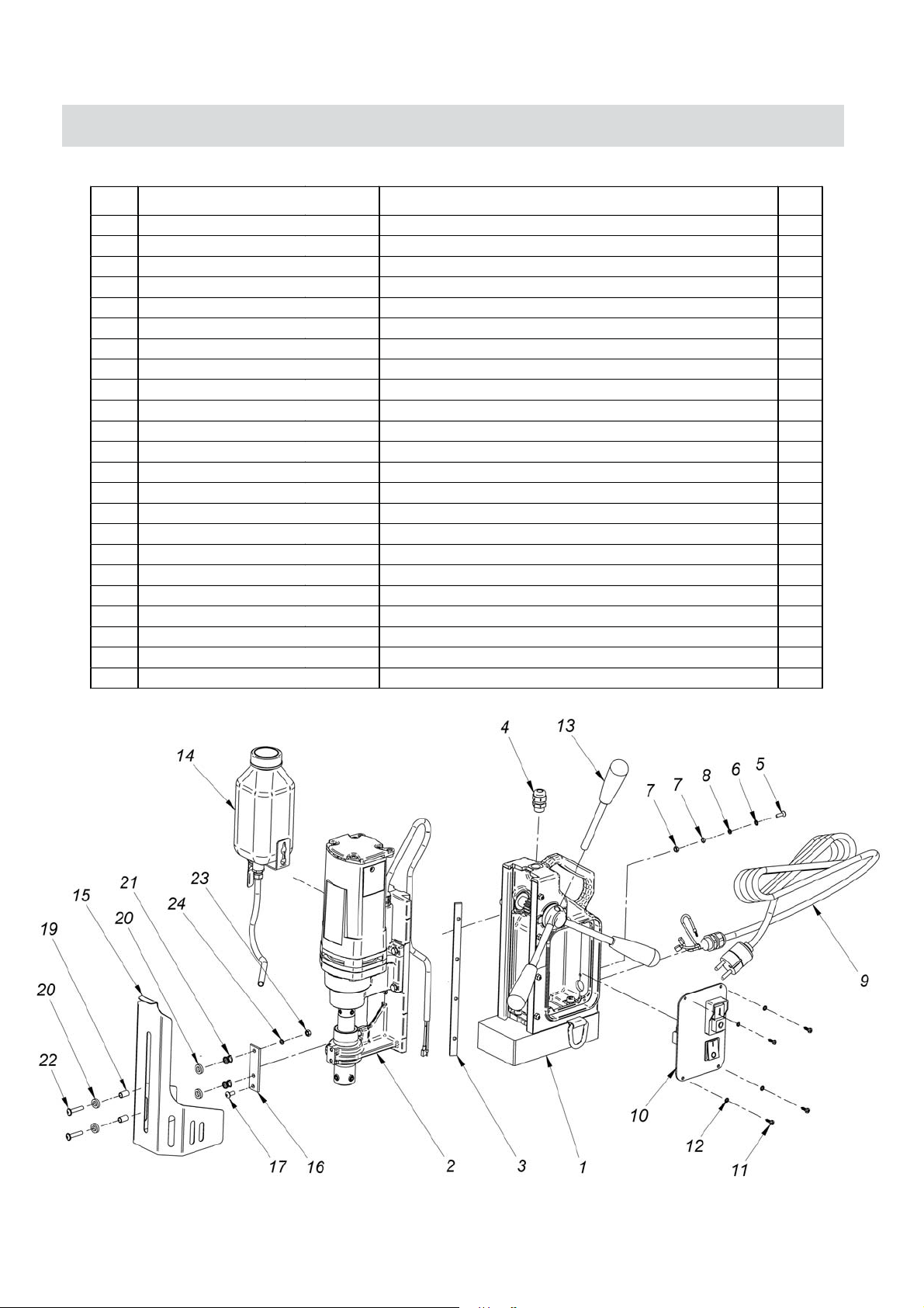
ITEM PART NUMBER
1 SEE FRAME ASSEMBLY PG14
2 SLIDE ASSEMBLY 230V 1
SEE FRAME ASSEMBLY PG20
FRAME ASSEMBLY, 1
DESCRIPTION
QTY
3 SPMT35106N PLATE SLIDE INSERT 1
4 NYLON GLAND 1
5 CROSS RECESSED SCREW -M4X16 1
6 SPRING WASHER-4.1 1
7 HEX NUT M4 2
8 SPRING WASHER 4,3 1
9 SPHM35705 POWER CORD 230V 3x1 1
10
11
SPPRO4009
PANEL ASSEMBLY 1
CROSS RECESSED PAN HEAD TAPPING SCREW 3,5x13
4
12 SPRING WASHER EXTERNAL STAR 3,7 4
13 SPHM35407 SPOKE HANDLE INCLUDING KNOB 3
14 SPMT6 COOLANT SYSTEM 1
15 SPHMPRO4015 GUARD ASSEMBLY 1
16 SPHMPRO4016
BRACKET GUARDS 1
17 SCR, M5 x 12 FHSCS 1
19 SPHMPRO4019 LOWER SLEEVE, 2
20 SPHMPRO4020 NYLON WASHER SR1940, 4
21 SPHMPRO4021 PUSH SPRING, 2
22
SOCKET BUTTON HEAD CAP SCREW WITH FLANGE M5x25,
2
23 HEX NUT M5 1
24 SPRING WASHER M5 1
13
Page 14
MACHINE BREAKDOWN
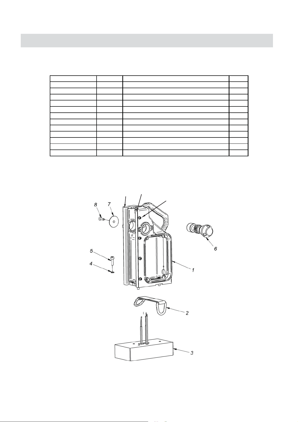
PART NUMBER
ITEM DESCRIPTION QTY
SPHM35101NEW
1YDOB NIAM1.1.1
SPMT35106R
1.1.3 SLIDE INSERT FLAT (RIGHT) 1
SPMT35106L
SPHM40109
SPHM40110
1.1.4 SLIDE INSERT DOVETAIL (LEFT) 1
402x5M - WERCS TES XEH5.1.1
45M TUN XEH6.1.1
SP6796
1PARTS GNIR-D2.1
SPHM200
1.3 ELECTROMAGNETIC BASE 1
31,6 REHSAW GNIRPS4.1
1.5 HEX. SOCKET BOLT M6x20 3
SPHM35401
1TFAHS NOINIP6.1
SPHM35405
1REHSAW7.1
1SCSHF 61 x 6M ,RCS8.1
FRAME ASSEMBLY
1.1.4
1.1.3
1.1.5
1.1.6
14
Page 15
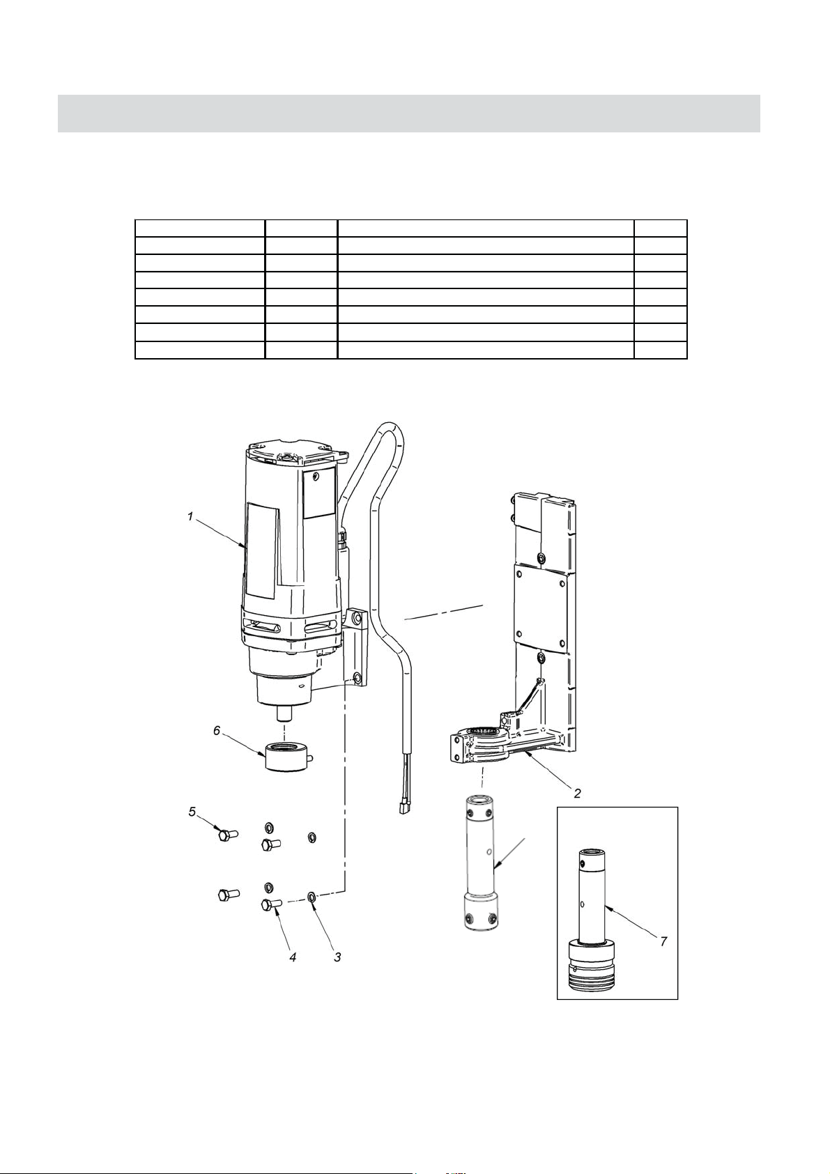
MACHINE BREAKDOWN
SLIDER ASSEMBLY
PART NUMBER
SPHM4021
SPHM35604
SPHM4027
SPHM35507
ITEM DESCRIPTION QTY
2.1 MOTOR ASSY 230V /INCL. GEARBOX/ 1
41,6 REHSAW GNIRPS3.2
28.8 - SCHH 61 x 6 M4.2
28.8 - SCHH 41 x 6 M5.2
1 GNIR TNALOOC6.2
1Y - QUICK GRIP TYPELBMESSA ROBRA7.2
1ARBOR ASSEMBLY - GRUB SCREW TYPE8.2
OPTIONAL
QUICK GRIP ARBOR
8
15
Page 16
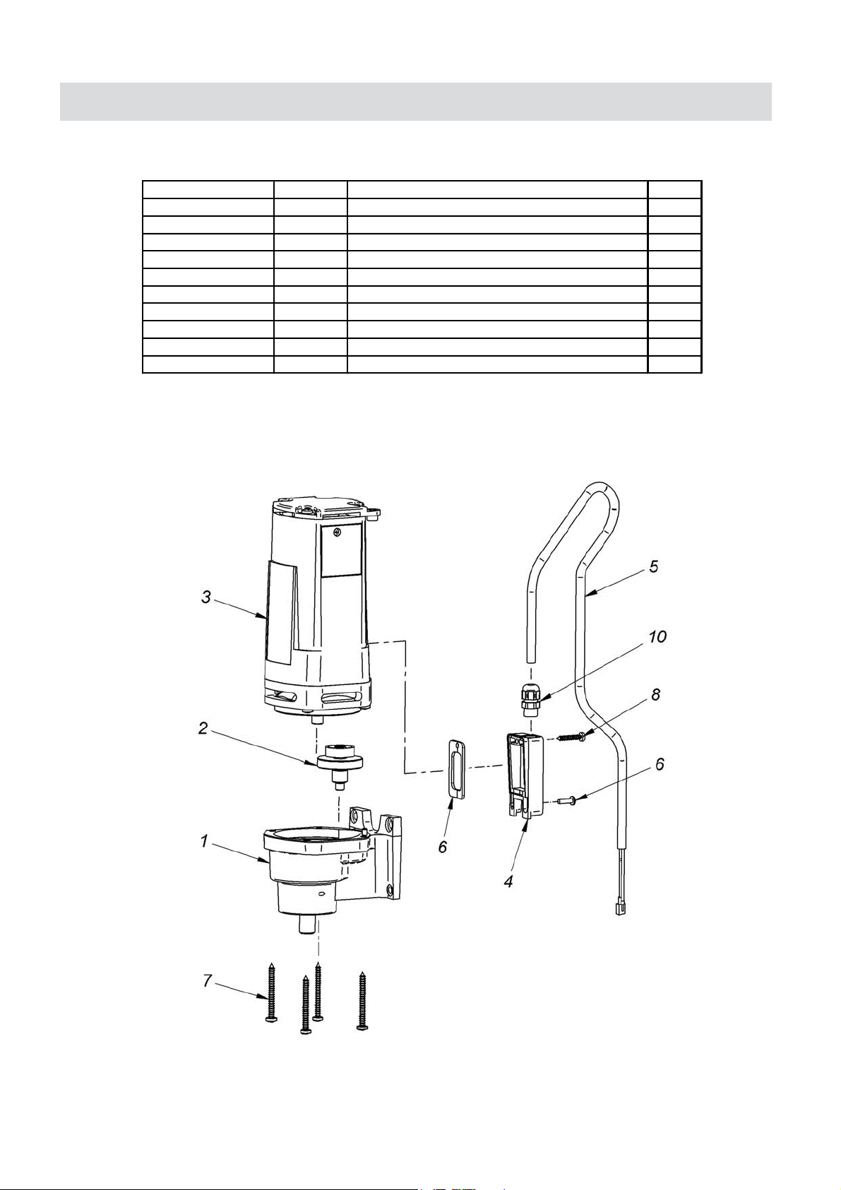
MACHINE BREAKDOWN
PART NUMBER
ITEM DESCRIPTION QTY
SPHM40211
1YLBMESSA XOBRAEG1.1.2
SPHM40212
1YLBMESSA TFAHS NOINIP2.1.2
SPHM40213
1V032 YLBMESSA ROTOM3.1.2
SPHM40214
1REVOC DROC ROTOM4.1.2
SPHM40215
1YLBMESSA DROC ROTOM5.1.2
SPHM40216
1LAES6.1.2
2.1.7 SELF-TAPPING SCREW 5x60 4
2.1.8 SELF-TAPPING SCREW 4x25 1
141X4M- WERCS9.1.2
17GP FEILEIR NIARTS01.1.2
MOTOR & GEARBOX ASSEMBLY
16
Page 17
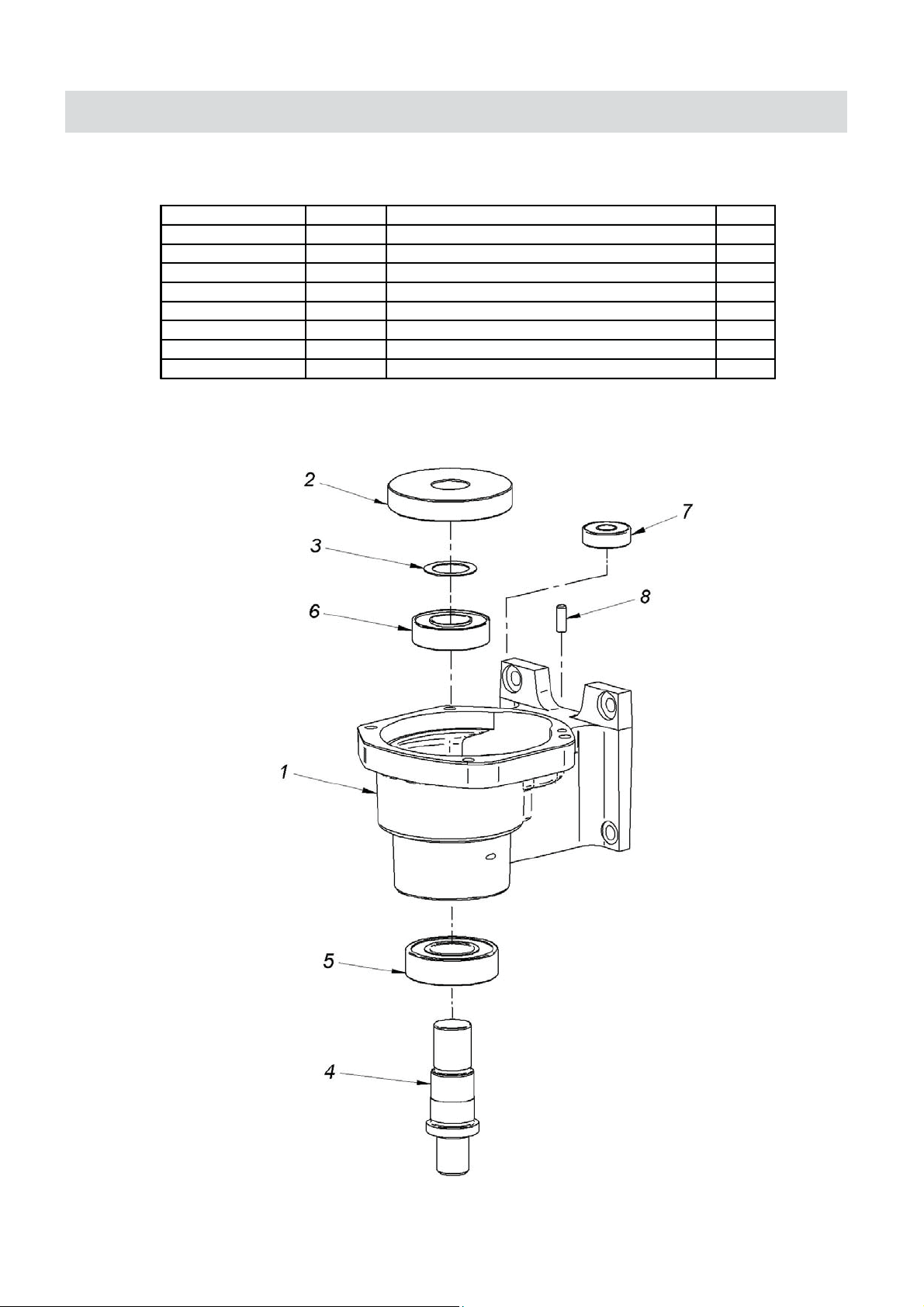
MACHINE BREAKDOWN
GEARBOX
PART NUMBER
SPHM402111
SPHM402112
SPHM402113
SPHM402114
BE6004ZZ
BE6003
BE608Z
SPHM402118
ITEM DESCRIPTION QTY
1ESACRAEG1.1.1.2
174=T RAEG2.1.1.2
1REHSAW RAEG3.1.1.2
1ELDNIPS4.1.1.2
14006 LLAB GNIRAEB5.1.1.2
ULL 3006 GNIRAEB6.1.1.2
1
1Z2 806 GNIRAEB7.1.1.2
121x4 NIP8.1.1.2
17
Page 18
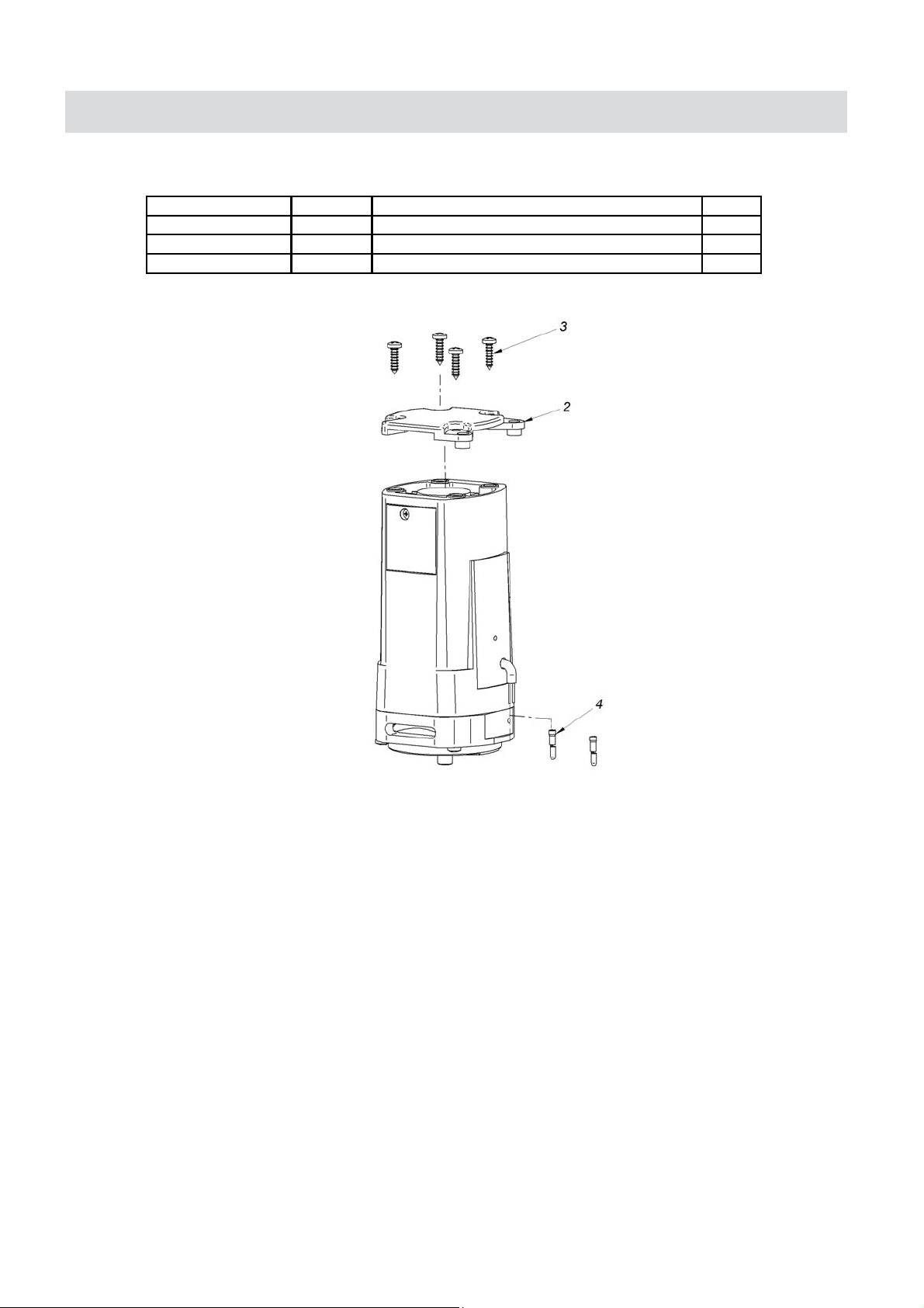
MACHINE BREAKDOWN
MOTOR
PART NUMBER
SPHM402132
ITEM DESCRIPTION QTY
1ESACDLEIF,REVOC2.3.1.2
2.1.3.3 SELF-TAPPING SCREW 5x20 4
2P-1-4BROTCENNOC4.3.1.2
18
Page 19
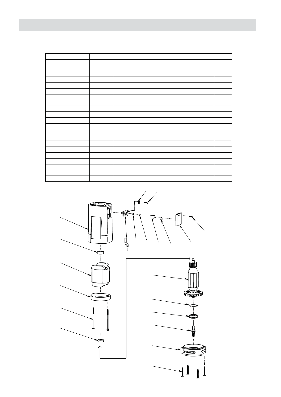
MACHINE BREAKDOWN
MOTOR
Part No.
SPHM4021311 2.1.3.1.1 GEARBOX COVER
SPHM4021312 2.1.3.1.2 GEAR SHAFT
SPHM4021313 2.1.3.1.3 ARMATURE 230V
BE627ZZ 627ZZ
2.1.3.1.4 BEARING 629ZZ TNG C3 S
BE629ZZ
BE6201DW
SPHM4021316 2.1.3.1.6 INTERNAL RETAINING RING 32W
SPHM4021317 2.1.3.1.7 FIELD FRAME
SPHM4021318 2.1.3.1.8 FIELD 230V
SPHM4021319 2.1.3.1.9 FIELD SHIELD
SPHM40213111 2.1.3.1.11 RUBBER INSERT
SPHM40213112 2.1.3.1.12 BRUSH HOLDER
SPHM40213113 2.1.3.1.13 PLATE 8x13
SPHM40213114 2.1.3.1.14 SPRING
SPHM40213115 2.1.3.1.15 MOTOR BRUSH 6,4x12,5x19
SPHM40213116 2.1.3.1.16 COVER
ITEM DESCRIPTION QTY
2.1.3.1.5 BEARING 6201 2BRS T9H C3
2.1.3.1.10 SCREW 5X85
2.1.3.1.17 SCREW TW4x13
2.1.3.1.18 SCREW Ph-TZ 3,5x13
2.1.3.1.19 SCREW M4x8-5.8b
2.1.3.1.20 SPRING WASHER 4,2x0,5
2.1.3.1.21 SCREW 5x55
13
19
1
1
1
1
1
1
1
1
1
2
1
2
2
2
2
2
2
2
2
2
4
07
11
08
09
10
04
12
20
17
03
06
05
02
01
15
14
18
16
21
19
Page 20
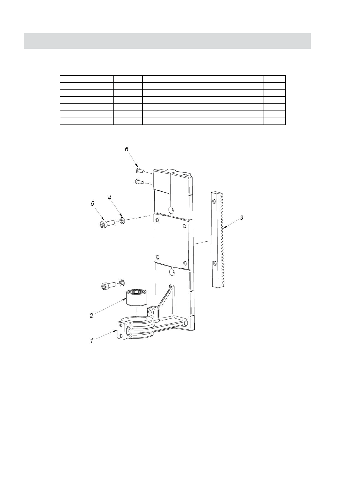
MACHINE BREAKDOWN
SLIDER ASSEMBLY
PART NUMBER
SPHM35301
SPHM35302
SPMT35403
ITEM DESCRIPTION QTY
1REDILS1.2.2
2.2.2 NEEDLE BEARING RHNA 253220 1
1KCAR RAEG3.2.2
21,6 REHSAW GNIRPS4.2.2
2.2.5 HEX. SOCKET BOLT M6X18 2
221X4M- WERCS6.2.2
20
Page 21
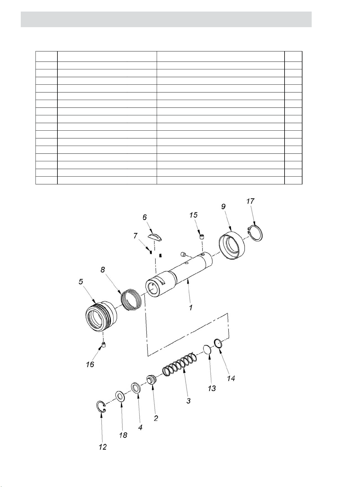
MACHINE BREAKDOWN
QUICK GRIP ARBOR ASSEMBLY
ITEM PART NUMBER DESCRIPTION
2.7.1 ARBOR BODY 1
2.7.2 PLUNGER 1
2.7.3 SPHM40273 SPRING 1,2x14,8x77,8 1
2.7.4 SPHM40274 SEAL 1
2.7.5 SPHM40275 SLEEVE CLAMP 1
2.7.6 SPHM40276 KEY 1
2.7.7 SPHM40277 KEY SPRING 2
2.7.8 SPHM40278 SLEEVE SPRING 1
2.7.9 SLEEVE 1
2.7.12 INTERNAL CIRCLIP 19 1
2.7.13 1
2.7.14 O-RING 14x1,25 1
2.7.15 INSERT SCREW M6 x0,75 x6 2
2.7.16 SPHM402716 SCREW M5x8
2.7.17 EXTERNALE CIRCLIP 25
2.7.18 WASHER 16x1
SPHM35509
WASHER D=18,8x10x1
QTY
1
21
Page 22
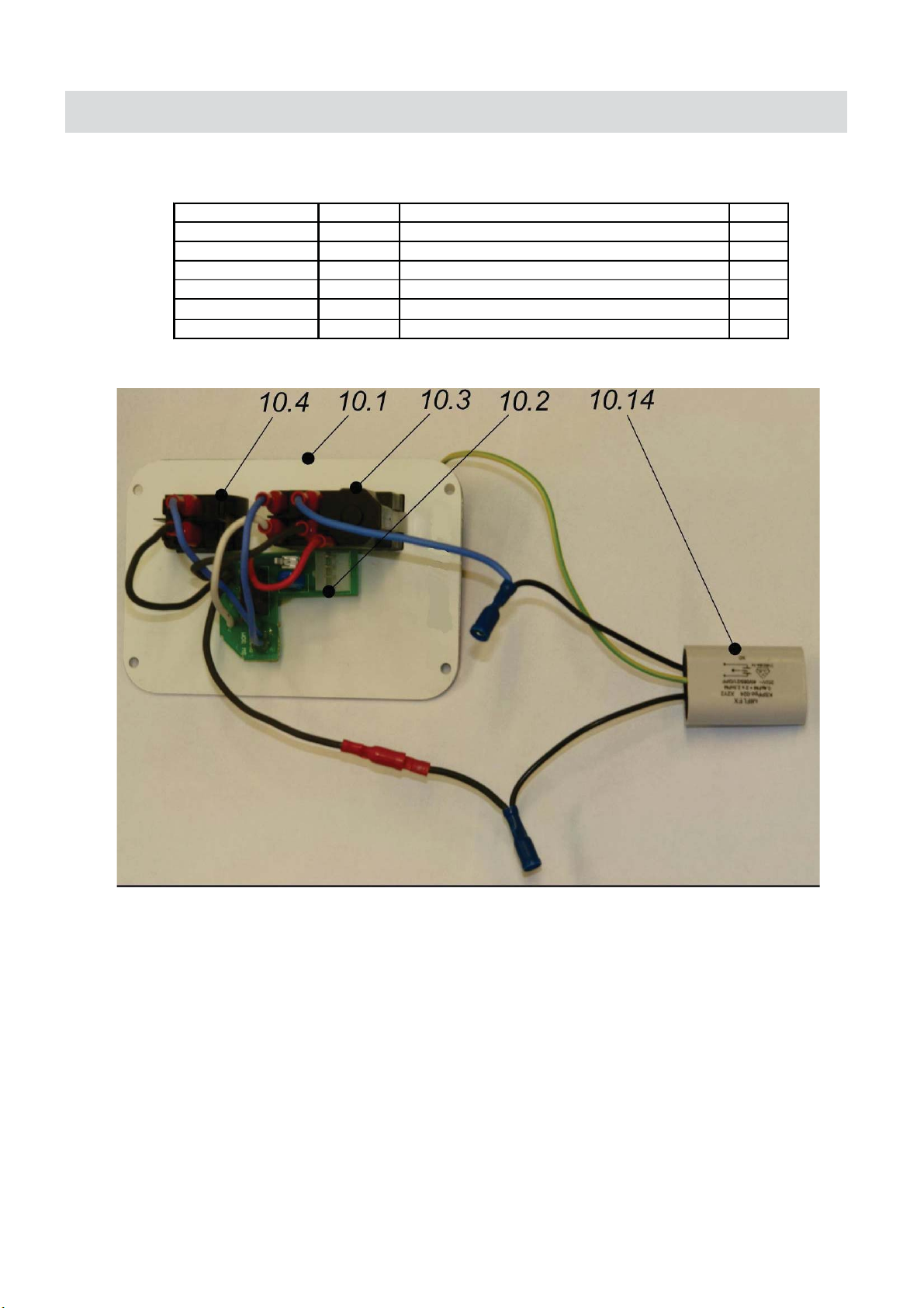
MACHINE BREAKDOWN
CONTROL PANEL ASSEMBLY
PART NUMBER
SPPRO4091
SPHM300403
SPHM300405
SPHM4095
SPHM401014
ITEM DESCRIPTION QTY
10.1 PANEL PLATE / WITH LABEL 1
10.2 ELECTRONIC CONTROLLER SW-30 / 230V 1
10.3 START-STOP SWITCHSPHM300404
10.4 SWITCH, MAGNET HOLEMAKER 1
10.5
10.14
INTERFERENCE ELIMINATOR
RALLIP GNIKCOL
1
3
1
22
Page 23
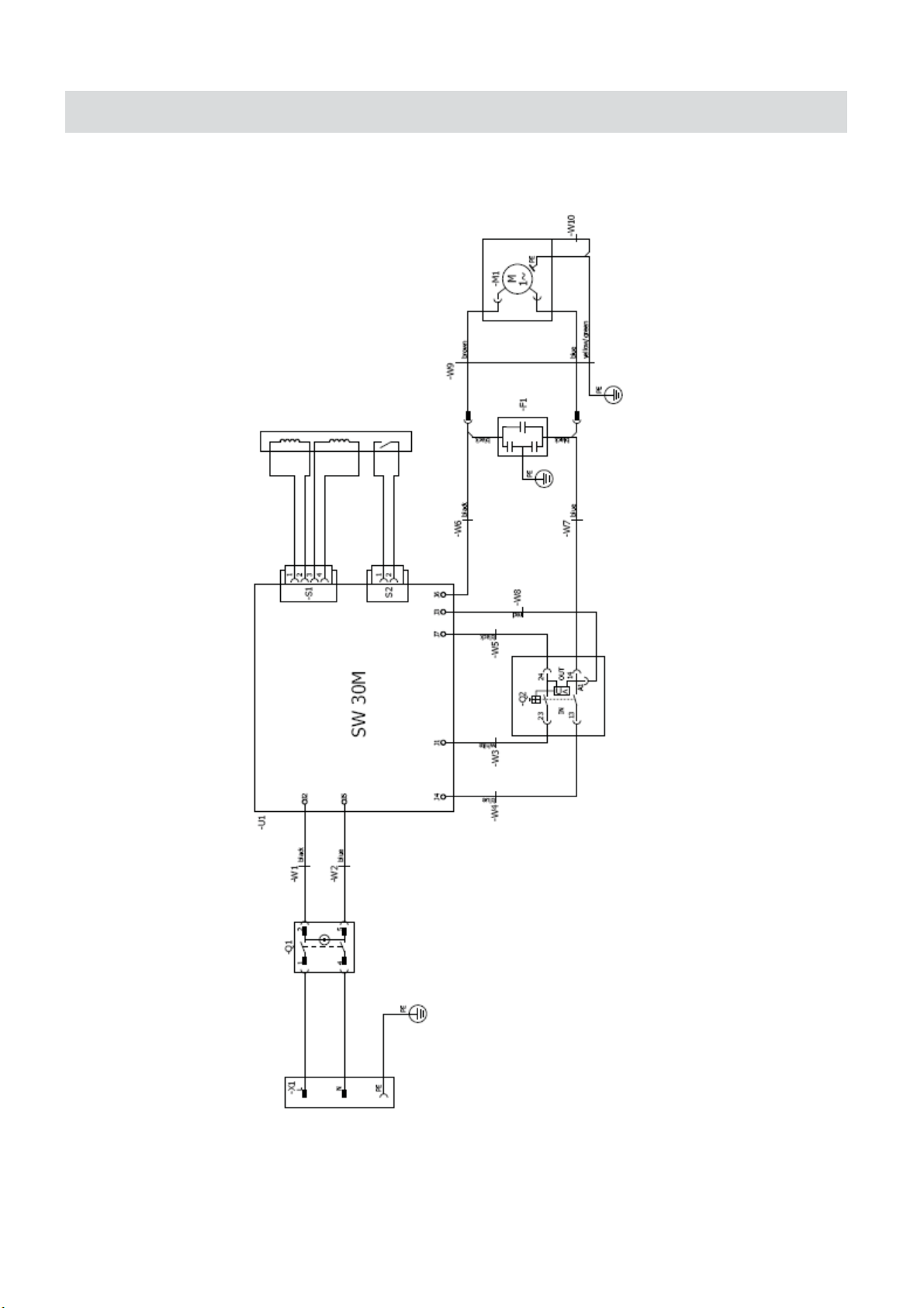
WIRING DIAGRAM
23
 Loading...