

Page 1
®
PRO 35 AUTO
DRILLING MACHINE
OPERATOR’S MANUAL
PART# HMPRO35AUTO
BEFORE USE, ENSURE EVERYONE USING THIS MACHINE READS AND UNDERSTANDS
ALL SAFETY AND OPERATING INSTRUCTIONS IN THIS MANUAL .
Serial #............................................ Date of Purchase............................
Ver: 1.1 07/10/2015
Page 2

HOLEMAKER PRO 35 AUTO DRILLING MACHINE
PRODUCTS IMPORTED AND DISTRIBUTED NATIONALLY BY:
INDUSTRIAL TOOL & MACHINERY SALES
18 BUSINESS ST, YATALA QLD 4207
T: 07 3287 1114 E: [email protected]
F: 07 3287 1115 W: www.industrialtool.com.au
WARRANTY TERMS
In addition to any warranties or conditions implied by applicable Statute or Regulations, Industrial
Tool & Machinery Sales warrants all of it’s products against defective workmanship and faulty
materials for a period of twelve (12) months from the date of purchase, unless otherwise stated.
At our option we will repair or replace, free of charge, any item on the condition that:
• The complete machine or tool is returned, freight prepaid to ITM or one of it’s authorised
service agents as directed by ITM, and is found to have a material or constructional defect.
• The machine or tool has not been subject to misuse, neglect or damage by accident.
• The fault is not a result of normal “wear and tear”.
• Written permission has been received from ITM prior to commencement of repair.
• Repairs, tampering or modification carried out by unauthorised personnel will void all warranty.
• Consumable items such as cutting tools, pilot pins, saw blades, grinding wheels etc. are NOT
covered by warranty.
Our goods come with guarantees which cannot be excluded under the Australian Consumer
Law. You are entitled to replacement or refund for a major failure and to compensation for other
reasonably foreseeable loss or damage. You are also entitled to have the goods repaired or
replaced if the goods fail to be of acceptable quality and the failure does not amount to a major
failure.
2
Page 3

HOLEMAKER PRO 35 AUTO DRILLING MACHINE
TABLE OF CONTENTS
1. GENERAL INFORMATION - 4 -
1.1. Application - 4 -
1.2. Technical data - 4 -
1.3. Design - 5 -
1.4. Equipment included - 6 -
2. SAFETY INSTRUCTIONS - 6 -
3. START UP AND OPERATION - 8 -
3.1. Mounting and operating the annular cutter - 8 -
3.2. Mounting and dismounting the cooling system bottle - 10 -
3.3. Control system of the electromagnetic base holding force - 10 -
3.4. Preparing - 11 -
3.5. Drilling - 13 -
3.6. Replacing the motor brushes - 14 -
3
Page 4

GENERAL INFORMATION
PRO 36 AUTO
PRO 36 AUTO
1. GENERAL INFORMATION
1.1. Application
The PRO 36 AUTO is a drilling machine with electromagnetic base designed to drill
holes with diameters of 12–36 mm (0.47–1.42’’) to the maximum depth of 51 mm (2’’)
through the use of annular cutters.
The electromagnetic base allows the drilling machine to be fixed to ferromagnetic
surfaces with a force that ensures user safety and proper machine operation. A safety
strap protects the machine from dropping in case of a power loss.
1.2. Technical data
1. GENERAL INFORMATION
1.1. Application
The PRO 35 AUTO is a drilling machine with electromagnetic base designed to drill holes
with diameters of 12–36 mm (0.47’’–1.42’’) to the maximum depth of 51 mm (2’’) through
the use of annular cutters.
The electromagnetic base allows the drilling machine to be xed to ferromagnetic
surfaces with a force that ensures user safety and proper machine operation. A safety
strap protects the machine from dropping in case of a power loss.
1.2. Technical data
Voltage
Total power 1000 W
Motor power 920 W
Cutter holder 19 mm Weldon (0.75’’)
Maximum drilling diameter 36 mm (1.42’’)
Maximum drilling depth 51 mm (2’’)
Electromagnetic base holding force
(surface with the thickness of 22 mm and roughness Ra = 1.25)
Electromagnetic base dimensions
Slider stroke 70 mm (2.8’’)
Rotational speed under load 350 rpm
Rotational speed without load 580 rpm
Minimum workpiece thickness 6 mm (0.23’’)
Protection class I
Noise level over 85 dB
Vibration level under 2.5 m/s
Required ambient temperature 0–40 °C (32–104 °F)
Weight 13.5 kg (30 lbs)
1~ 110–120 V, 50–60 Hz
1~ 220–240 V, 50–60 Hz
9 300 N
80 mm × 160 mm × 36.5 mm
3.1’’ × 6.3’’ × 1.4’’
2
(≤ 8.2 ft/s2)
4
Page 5
GENERAL INFORMATION
PRO 36 AUTO
316 mm (12.4’’)
313 mm (12.3’’)
221 mm (8.7’’)
PRO 36 AUTO
Figure 7. Securing the drilling machine using the safety strap
When working in the position from Figure 7a, mount the cooling system bottle as
described before and
fill it with a cutting fluid. Do not use pure water as the cutting
fluid, however, using emulsions formed from mixing water and drilling oil is also
satisfactory. To check the operation of the cooling system, slightly loosen the bottle
cap, open the valve using the lever, and initially apply pressure on the pilot pin by
rotating the spoke handles counterclockwise. The fluid should fill the system and
should begin flowing from the inside of the cutter.
Enter into manual feed mode by positioning the spoke handles as shown in Figure 8a,
and
rotate them counterclockwise to place the tip of the pilot pin above the drilling
b)
The cooling system works by means of gravitation, therefore use
a cooling paste when working in horizontal or inverted positions
.
PRO 36 AUTO
313 mm (12.3’’)
PRO 36 AUTO
point.
316 mm (12.4’’)
221 mm (8.7’’)
261 mm
a)
313 mm (12.3’’)
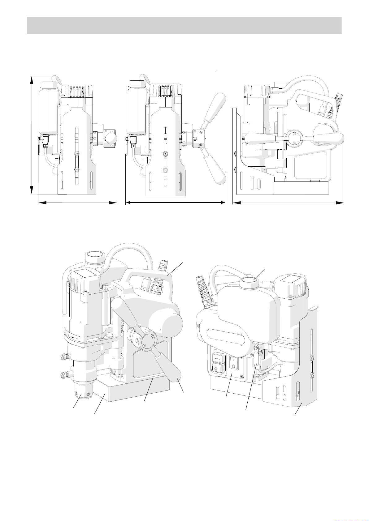
1.3. Design
carrying handle
spoke handle
control panel
arbor
opening for safety strap
electromagnetic base
cooling system bottle
bottle valve lever
chip guard
5
Page 6
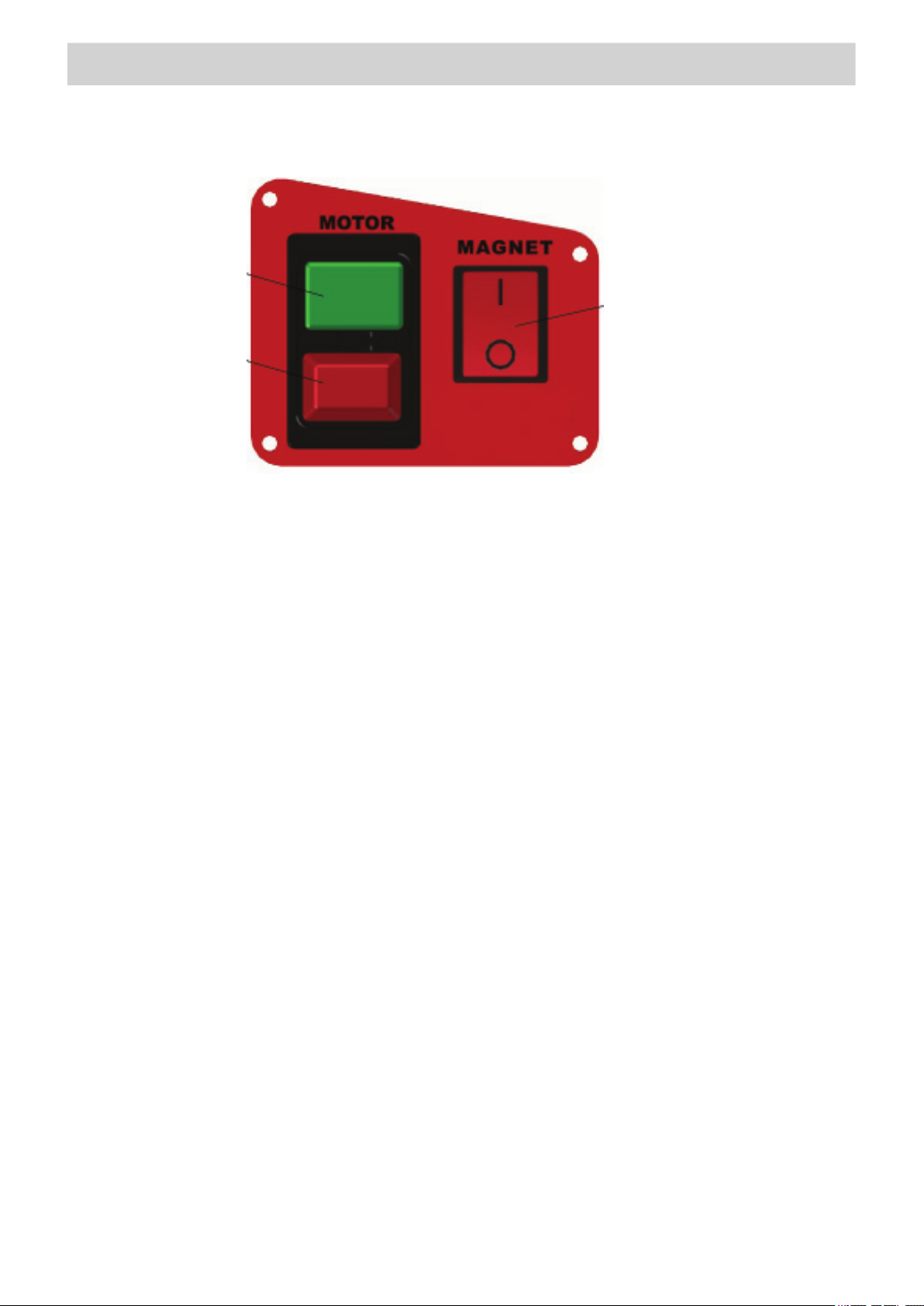
Motor START button
Motor STOP button
GENERAL INFORMATION
Electromagnetic
base ON/OFF switch
Figure 2. Control panel design
1.4. Equipemnt included
The PRO 35 AUTO is supplied in a metal box with complete standard equipment.
The included equipment consists of:
• 1x Drilling machine
• 1x Metal box
• 2x Spoke handle
• 1x Cooling system bottle
• 1x Chip guard
• 1x Safety strap
• 1x 4mm hex wrench
• 1x Operator’s manual
2. Safety instructions
1. Before beginning, read this Operator’s Manual and complete proper occupational health
and safety training.
2. The machine must be used only in applications specied in this Operator’s Manual.
3. The machine must be complete and all parts must be genuine and fully operational.
4. The electrical supply specications must conform to those specied on the rating plate.
5. The machine must be plugged into a properly grounded (earthed) socket-outlet. The
electrical supply must be protected with a 16 A fuse for 230 V. When used on building
sites, supply the machine through an isolation transformer made with class II protection
only.
6. Never carry the machine by the cord or pull it to disconnect the plug from the power
outlet as this may damage the power cord and result in electric shock.
7. Transport and position the machine using the carrying handle, with the magnet switch
set to position ‘O’ (off).
6
Page 7

SAFETY INSTRUCTIONS
8. Untrained bystanders must not be present in the vicinity of the machine.
9. Before beginning, check the condition of the machine and electrical supply,
including the power cord, plug, control panel components, and cutters.
10. Keep the machine dry. Exposure to rain, snow, or frost is prohibited.
11. Never stay below the machine placed at heights.
12. Keep the work area well lit, clean, and free of obstacles.
13. Mount the annular cutter securely using the set screws. Remove adjusting keys
and wrenches from the work area before connecting the plug to the power outlet.
14. Never use dull or damaged cutters.
15. Mount and dismount cutters using protective gloves and with the power cord
unplugged from the power outlet.
16. Never use annular cutters without the pilot pin except when drilling incomplete
through holes.
17. Mount only annular cutters with the maximum drilling diameter of 36 mm (1.42’’)
and the maximum drilling depth of 55 mm (2.17’’).
18. Never use the machine in the vicinity of ammable liquids or gases, or in
explosive environments.
19. Using the machine on surfaces that are rusty, covered with a thick paint layer,
uneven, or not rigid is prohibited.
20. Use the safety strap in all operating positions. The strap must be tight and
fastened to a securely xed element either through the opening in the machine
body or by catching the strap on the carrying handle. Never insert the strap into
the buckle from the front.
21. Before every use, inspect the machine to ensure it is not damaged. Check
whether any part is cracked or improperly tted. Make sure to maintain proper
conditions that may affect the operation of the machine.
22. Always use eye and hearing protection and protective clothing during operation.
Do not wear loose clothing.
23. Proceed with caution when drilling plate with a thickness less than 10 mm (0.4’’)
as the adhesion force depends on material thickness and is signicantly lower for
thin plate.
24. The entire surface of the electromagnetic base bottom must be in full contact with
the workpiece. Before every positioning, wipe the workpiece with coarse-grained
sandpaper.
25. Do not touch moving parts or chips formed during milling. Prevent objects from
being caught in moving parts.
26. After every use, remove metal chips and excess coolant from the machine. Do
not remove chips with bare hands.
27. Maintain the machine and tools with care. Cover steel parts with a thin grease
layer to protect them against rust when not in use for any extended period.
28. Perform maintenance only with the machine unplugged from the power outlet.
29. All repairs must only be performed by an ITM approved repairer or service agent.
30. If the machine falls on from any height, is wet, or has any other damage
that could affect the safe operation of the machine, stop the operation and
immediately send the machine to the service centre for inspection and repair.
31. Never leave the machine unattended during operation.
32. Remove from the worksite and store in a secure and dry location, when not in use
remove the cutter and pin from the arbor.
7
Page 8
START UP AND OPERATION
PRO 36 AUTO
3. STARTUP AND OPERATION
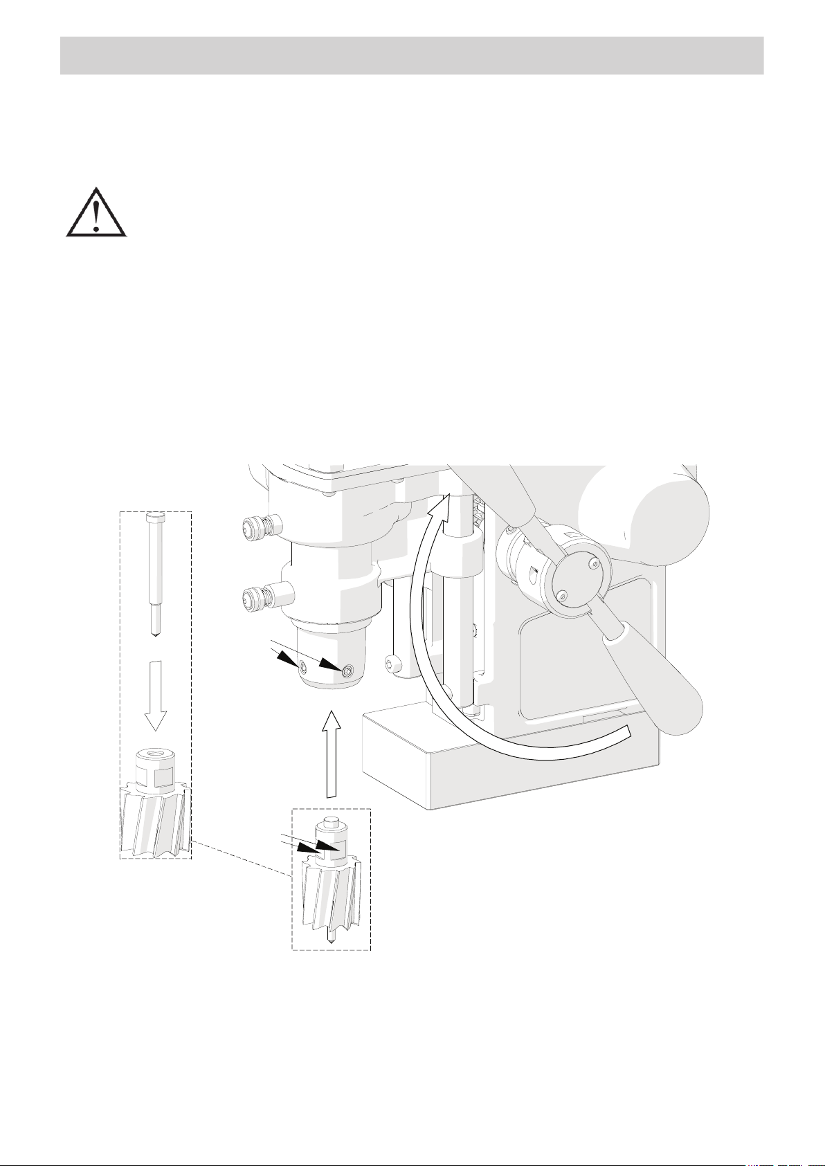
3.1. Mounting and operating the annular cutter
Unplug the power cord from the power outlet and raise the motor by rotating the
spoke handles clockwise (1, Figure 3). Insert the proper pilot pin into the annular
cutter (2), then wear protective gloves and place the cutter into the arbor (3) in such
a way to align the flats 4 with the set screws 5. Finally, tighten both set screws with
the supplied 4 mm hex wrench. To dismount the cutter, proceed in reverse order.
All safety precautions must be closely observed.
PRO 36 AUTO
Figure 7. Securing the drilling machine using the safety strap
When working in the position from Figure 7a, mount the cooling system bottle as
described before and fill it with a cutting fluid. Do not use pure water as the cutting
fluid, however, using emulsions formed from mixing water and drilling oil is also
satisfactory. To check the operation of the cooling system, slightly loosen the bottle
cap, open the valve using the lever, and initially apply pressure on the pilot pin by
rotating the spoke handles counterclockwise. The fluid should fill the system and
should begin flowing from the inside of the cutter.
The cooling system works by means of gravitation, therefore use
a cooling paste when working in horizontal or inverted positions.
3. START UP AND OPERATION
All safety precautions must be adhered to.
3.1. Mounting and operating the annular cutter
Unplug the power cord from the power outlet and raise the motor by rotating the spoke
handles clockwise (1, Figure 3). Insert the proper pilot pin into the annular cutter (2), then
wear protective gloves and place the cutter into the arbor (3) in such a way to align the ats
4 with the set screws 5. Finally, tighten both set screws with the supplied 4 mm hex wrench.
To remove the cutter, proceed in reverse order.
1
5
2
3
4
Figure 3. Mounting the annular cutter
8
Page 9
START UP AND OPERATION
PRO 36 AUTO
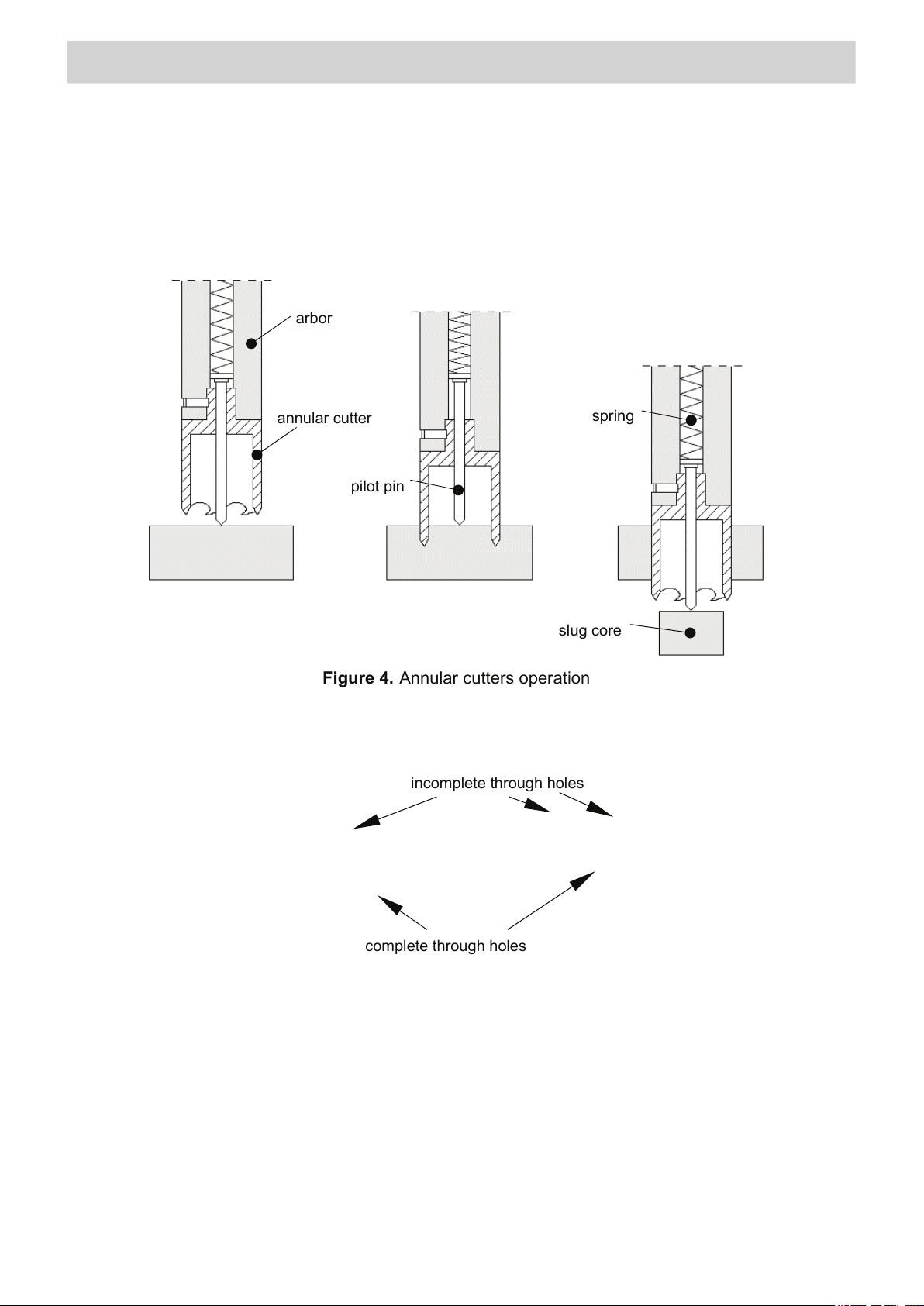
Figure 4 shows how annular cutters operate. As the cutter penetrates the workpiece,
the pilot pin recesses into the arbor and tightens the spring. As a result, after the cutter
goes through the entire thickness, the slug core is expelled from the cutter.
Figure 4. Annular cutters operation
Annular cutters are designed to establish only through holes shown in Figure 5.
During establishing incomplete through holes the pilot pin must not be used.
incomplete through holes
complete through holes
slug core
spring
pilot pin
annular cutter
arbor
Figure 4 shows how annular cutters operate. As the cutter penetrates the workpiece, the
pilot pin recesses into the arbor and tightens the spring. As a result, after the cutter goes
through the entire thickness, the slug core is expelled from the cutter.
allows application of coolant to the inner surface of the annular cutter as it is depressed.
The pilot pin also
Annular cutters are designed to establish only through holes shown in Figure 5. When
drilling incomplete through holes the pilot pin must not be used.
Figure 5. Types of holes drilled with annular cutters
9
Page 10
START UP AND OPERATION
PRO 36 AUTO
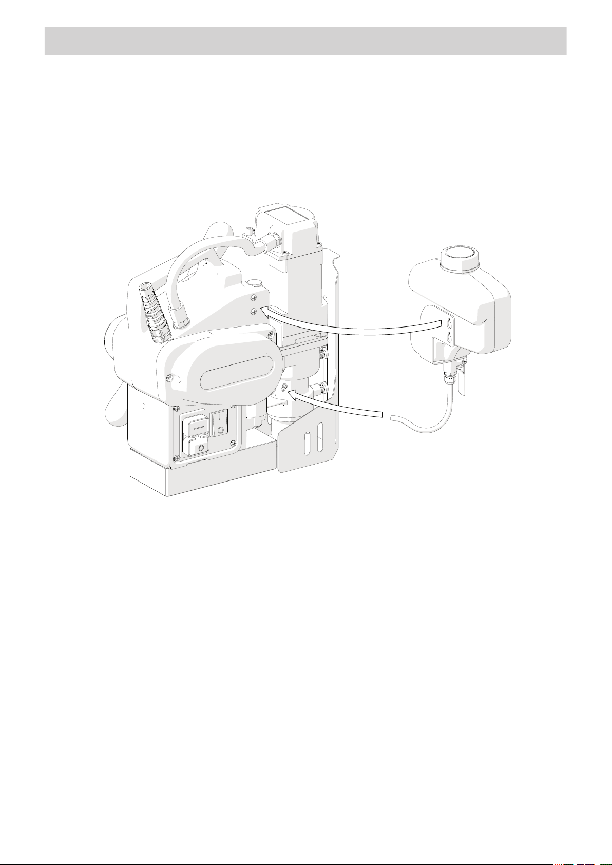
3.2. Mounting and dismounting the cooling system bottle
Hang the cooling system bottle on the screws (1, Figure 6) and attach the bottle hose
to the coupling (2). Dismount in reverse order.
3.2. Mounting and dismounting the cooling system bottle
Hang the cooling system bottle on the screws (1), (Figure 6) and attach the bottle hose to
the coupling (2). Dismount in reverse order.
1
2
Figure 6. Mounting the cooling system bottle
3.3. Control system of the electromagnetic base holding force
The PRO 35 AUTO drilling machine incorporates a holding force control system to monitor
the adhesion force of the electromagnetic base to the surface. The force value depends
on several factors; such as type, thickness, atness, and roughness of the surface,
presence of paint, rust or other contaminants, supply voltage uctuations, and the wear of
the electromagnetic base bottom. With the motor off, the base provides a fraction of the
maximum holding force. Once the motor is started, the holding force rises to the maximum.
If the holding force falls below a safe operating value, the control system will not
allow the machine to operate. Additionally, the system will prevent the startup of the motor
if the machine is placed on a surface thinner than 6 mm (0.23’’) as such thickness does not
provide sufcient holding force. In such case, the adhesion force will be only about 25 % of
the force attained on a standard 22 mm (0.87’’) at plate.
If the motor does not continue operation after the green MOTOR button is pushed
and released, it means that the control system is operating properly and preventing further
drilling because of too low adhesion force.
Always ensure the entire surface of the magnet base is in contact with the steel
workpiece.
10
Page 11
START UP AND OPERATION
PRO 36 AUTO
thickness does not provide sufficient holding force. In such case, the adhesion force
will be
only about 25 % of the force attained on a standard 22 mm (0.87’’) flat plate.
If the motor does not continue operation after the green MOTOR button is
pushed and released, it means that the control circuit is operating properly and
preventing further drilling because of too low adhesion force.
3.4. Preparing
Before beginning, clean steel parts, especially the Weldon shank, from grease used
to preserve the machine for storage and transport.
Mount the annular cutter into the arbor in the manner described before.
Position the machine on a flat ferromagnetic surface (some types of stainless
and acid-proof steel do not conduct magnetic flux) with the thickness of at least 6 mm
(0.23’’). The workpiece must be clean, without rust or paint that decrease the holding
force of the electromagnetic base.
Then, connect the drilling machine to the power outlet and enable the holding force
of the electromagnetic base by toggling the MAGNET switch to position ‘I’.
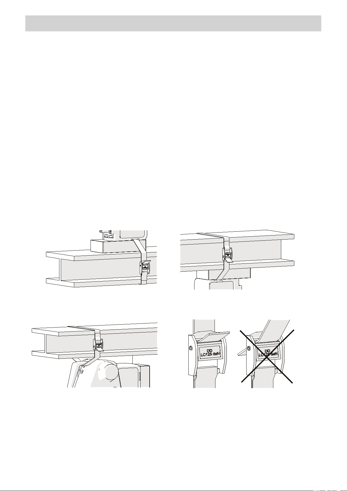
Protect the machine using the safety strap to prevent possible injury if the
machine loses magnetic adhesion in case of a power loss. In order to do this, either
mount the strap through the opening in the machine body (Figure 7a, 7b) or catch
the strap on the carrying handle when working in horizontal position (Figure 7c). The
strap must be tight, not twisted, and must be replaced every single time the machine
hangs on the strap as a result of coming loose from steel. Never insert the strap into
the buckle from the front (Figure 7d).
PRO 36 AUTO
thickness does not provide sufficient holding force. In such case, the adhesion force
will be only about 25 % of the force attained on a standard 22 mm (0.87’’) flat plate.
If the motor does not continue operation after the green MOTOR button is
pushed and released, it means that the control circuit is operating properly and
preventing further drilling because of too low adhesion force.
3.4. Preparing
Before beginning, clean steel parts, especially the Weldon shank, from grease used
to preserve the machine for storage and transport.
Mount the annular cutter into the arbor in the manner described before.
Position the machine on a flat ferromagnetic surface (some types of stainless
and acid-proof steel do not conduct magnetic flux) with the thickness of at least 6 mm
(0.23’’). The workpiece must be clean, without rust or paint that decrease the holding
force of the electromagnetic base.
Then, connect the drilling machine to the power outlet and enable the holding force
of the electromagnetic base by toggling the MAGNET switch to position ‘I’.
Protect the machine using the safety strap to prevent possible injury if the
machine loses magnetic adhesion in case of a power loss. In order to do this, either
mount the strap through the opening in the machine body (Figure 7a, 7b) or catch
the strap on the carrying handle when working in horizontal position (Figure 7c). The
strap must be tight, not twisted, and must be replaced every single time the machine
hangs on the strap as a result of coming loose from steel. Never insert the strap into
the buckle from the front (Figure 7d).
a) b)
3.4. Preparing
Before beginning, clean steel parts, especially the Weldon shank, from grease used to
preserve the machine for storage and transport.
Mount the annular cutter into the arbor in the manner described in (3.1).
Position the machine on a at ferromagnetic surface (some types of stainless and
acid-proof steel do not conduct magnetic ux) with the thickness of at least 6 mm (0.23’’).
The workpiece must be clean, without rust or paint that decrease the holding force of the
electromagnetic base.
Then, connect the drilling machine to the power outlet and enable the holding force of
the electromagnetic base by toggling the MAGNET switch to position ‘I’ (on).
Protect the machine using the safety strap to prevent possible injury if the machine
loses magnetic adhesion in case of a power loss. In order to do this, either mount the strap
through the opening in the machine body (Figure 7a, 7b) or catch the strap on the carrying
handle when working in horizontal position (Figure 7c). The strap must be tight, not twisted,
and must be replaced every single time the machine hangs on the strap as a result of
coming loose from steel. Never insert the strap into the buckle from the front (Figure 7d).
a) b)
Vertical drilling
c)
Inverted drilling
d)
INCORRECT
Horizontal drilling
CORRECT
Figure 7. Securing the drilling machine using the safety strap
11
Page 12
START UP AND OPERATION
PRO 36 AUTO
Figure 7. Securing the drilling machine using the safety strap
When working in the position from Figure 7a, mount the cooling system bottle as
described before and fill it with a cutting fluid. Do not use pure water as the cutting
fluid, however, using emulsions formed from mixing water and drilling oil is also
satisfactory. To check the operation of the cooling system, slightly loosen the bottle
cap, open the valve using the lever, and initially apply pressure on the pilot pin by
rotating the spoke handles counterclockwise. The fluid should fill the system and
should begin flowing from the inside of the cutter.
Enter into manual feed mode by positioning the spoke handles as shown in Figure 8a,
and
rotate them counterclockwise to place the tip of the pilot pin above the drilling
The cooling system works by means of gravitation, therefore use
a cooling paste when working in horizontal or inverted positions.
PRO 36 AUTO
Figure 7. Securing the drilling machine using the safety strap
When working in the position from Figure 7a, mount the cooling system bottle as
described before and fill it with a cutting fluid. Do not use pure water as the cutting
fluid, however, using emulsions formed from mixing water and drilling oil is also
satisfactory. To check the operation of the cooling system, slightly loosen the bottle
cap, open the valve using the lever, and initially apply pressure on the pilot pin by
rotating the spoke handles counterclockwise. The fluid should fill the system and
should begin flowing from the inside of the cutter.
The cooling system works by means of gravitation, therefore use
a cooling paste when working in horizontal or inverted positions
.
When working in the position from Figure 7a, mount the cooling system bottle as described
before and ll it with a cutting uid. Do not use pure water as the cutting uid. However, using
emulsions formed from mixing water and drilling oil is satisfactory.
cooling system, slightly loosen the bottle cap, open the valve using the lever, and initially apply
pressure on the pilot pin by rotating the spoke handles counterclockwise. The uid should ll the
system and should begin owing from the inside of the cutter.
To check the operation of the
The cooling system works by means of gravitation,
therefore use a cooling paste when working in
horizontal or inverted positions.
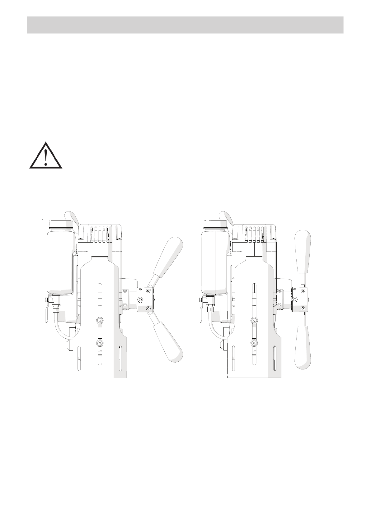
Enter into manual feed mode by positioning the spoke handles as shown in Figure 8a, and
rotate them counterclockwise to place the tip of the pilot pin above the drilling point.
point.
a)
b)
Figure 8. Configuration of the spoke handles: manual feed (a), automatic feed (b)
12
Page 13

START UP AND OPERATION
PRO 36 AUTO
Figure 7. Securing the drilling machine using the safety strap
When working in the position from Figure 7a, mount the cooling system bottle as
described before and fill it with a cutting fluid. Do not use pure water as the cutting
fluid, however, using emulsions formed from mixing water and drilling oil is also
satisfactory. To check the operation of the cooling system, slightly loosen the bottle
cap, open the valve using the lever, and initially apply pressure on the pilot pin by
rotating the spoke handles counterclockwise. The fluid should fill the system and
should begin flowing from the inside of the cutter.
The cooling system works by means of gravitation, therefore use
a cooling paste when working in horizontal or inverted positions.
3.5. Drilling
Start the motor by pressing the green MOTOR button. Slowly rotate the spoke handles
counterclockwise to bring the cutter close to the workpiece. Then, gently begin drilling and
enter into the automatic feed mode by setting the spoke handles in the position shown in
Figure 8b. The drilling machine will automatically detect the end of the drilling, which will
stop the feed after the hole is accomplished, however, the motor will still be rotating.
When the cutter goes through the material, the slug
core is expelled from the tool with a signicant force.
Once the hole is accomplished, toggle the spoke handles into the manual feed mode
(Figure 8a). Then, retract the cutter from the workpiece and stop the motor using the
red MOTOR button. To move the machine to another drilling spot, rst disable the
electromagnetic base by toggling the MAGNET switch to position ‘O’ (off).
Once the work is nished, unplug the machine from the power outlet, clean chips and
excess coolant from the machine and cutter, and remove the machine from the worksite.
Tighten the cap of the cooling system bottle, close the valve, and press the pilot pin
to expel the coolant remaining within the system. Before inserting the drilling machine into
the toolbox, disassemble the cooling system bottle and remove the cutter and pilot pin from
the arbor using protective gloves.
13
Page 14
START UP AND OPERATION
PRO 36 AUTO
3.6. Replacing the motor brushes
Check the condition of the carbon brushes every 100 operational hours. If the length
of the brushes is less than
5 mm (0.2’’), replace them with new ones. To do this,
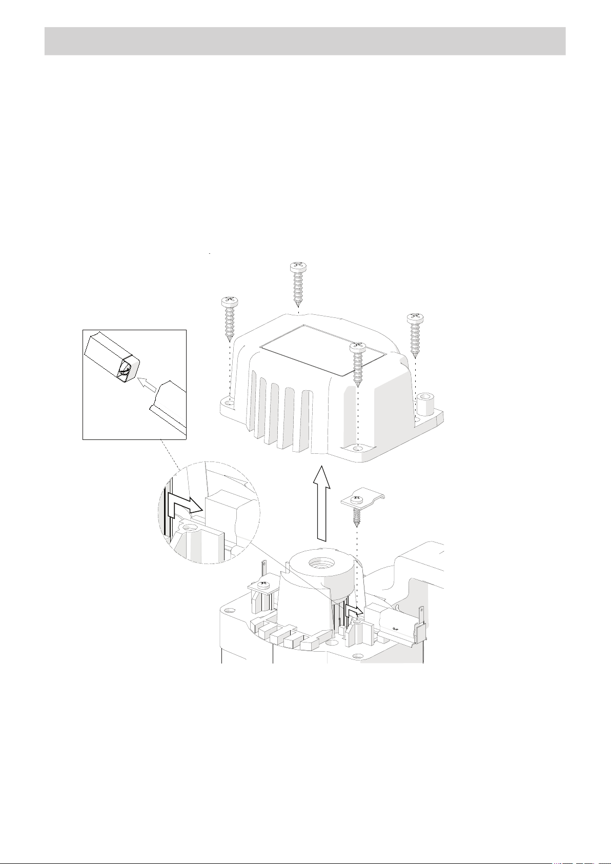
unplug the power cord from the power outlet, and unscrew four mounting screws (1,
Figure 9) to remove the motor cover (2). Then, unscrew the pressing plate 3, remove
the brush holder (4) and the brush (5). Proceed as described also for the second
brush located at the opposite side of the motor. To mount brushes, proceed in
reverse order. After the replacement, run the motor without load for 20 minutes.
3.6. Replacing the motor bushes
Check the condition of the carbon brushes every 100 operational hours. If the length of the
brushes is less than 5 mm (0.2’’), replace them with new ones. To do this, unplug the power
cord from the power outlet, and unscrew four mounting screws (1), (Figure 9) to remove the
motor cover (2). Then, unscrew the pressing plate (3), remove the brush holder (4) and the
brush (5). Proceed as described also for the second brush located at the opposite side of
the motor. To mount brushes, proceed in reverse order. After the replacement, run the motor
without load for 20 minutes.
5
1
4
2
3
Figure 9. Replacing the brushes
14
Page 15

NOTES
15
Page 16
HOLEMAKER ANNULAR CUTTER GUIDE
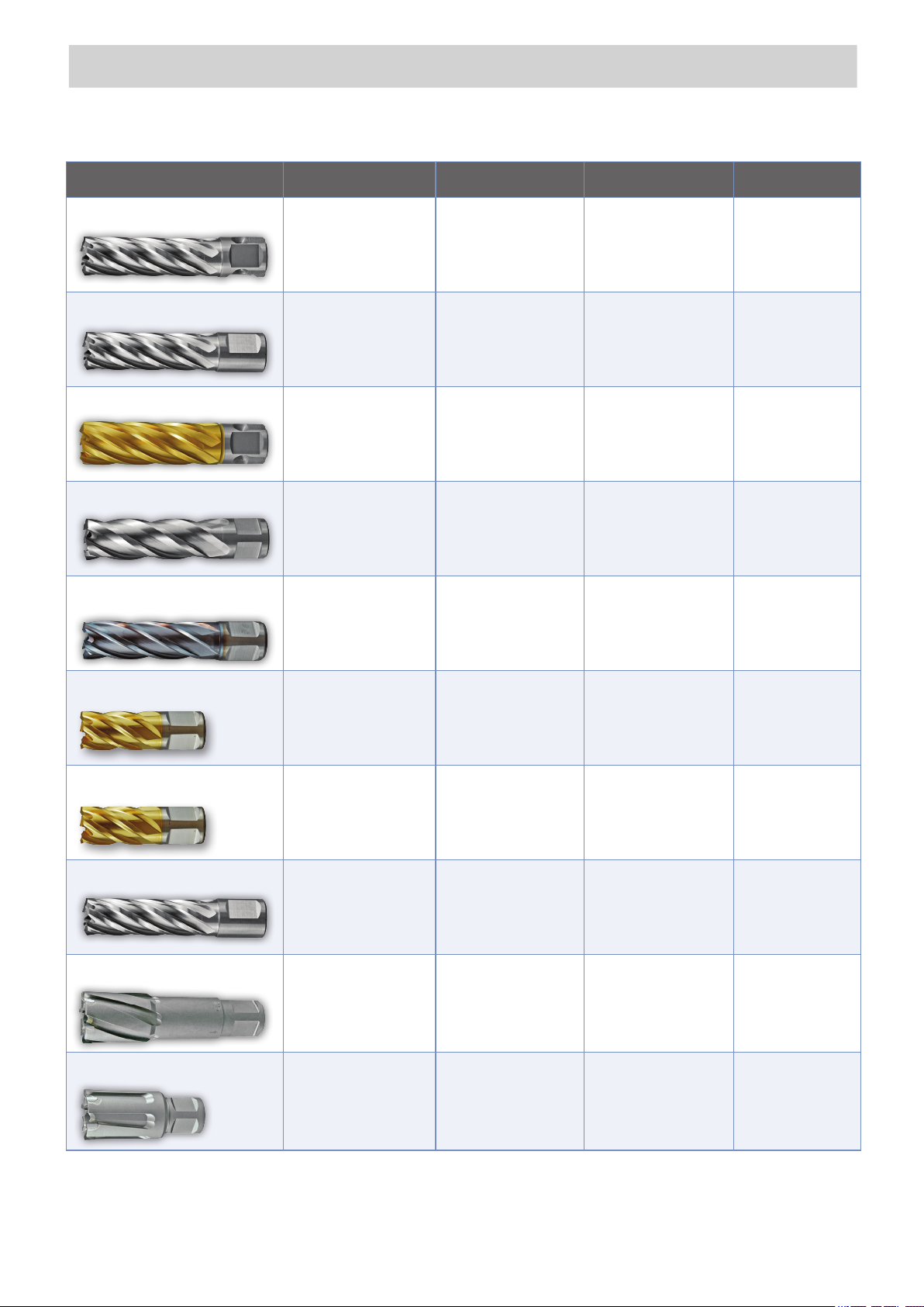
Cutter Type Features Diameter Available Cut Depth Available Applications
Silver Series Metric
Silver Series Imperial
Gold Series Metric
Super-Cut
Super-Cut TICN
• M2AL High Speed Steel
• Universal Shank
• Multi-Cut Geometry
• Step Hardened
• M2AL High Speed Steel
• Multi-Cut Geometry
• Step Hardened
• M2AL High Speed Steel
• Titanium Nitride Coated
• Universal Shank
• Multi-Cut Geometry
• Step Hardened
• Made In U.S.A
• Highest Quality
• M2 High Speed Steel
• Multi-Cut Geometry
• Titanium Carbon
Nitride Coated
• Made In U.S.A
• M2 High Speed Steel
• Multi-Cut Geometry
• 12 to 60mm Metric • 25mm & 50mm • General Purpose
• 7/16" to 2-1/4" Imperial • 1", 2" & 3" • General Purpose
• 12 to 60mm Metric • 25mm, 50mm & 75mm • General Purpose
• 12 to 60mm Metric
• 7/16" to 2-1/2" Imperial
• 12 to 32mm Metric • 25mm & 50mm
• 25mm, 50mm & 75mm
• 1", 2" & 3"
• General Purpose
• Stainless Steel
• Cast Iron
Super-Cut M42 Cobalt
Super-Cut M42 Chassis
Pro-Cut
Maxi-Cut
Maxi-Rail
• M42 High Speed Steel
• 8% Cobalt
• Titanium Nitride Coated
• Made In U.S.A
• Multi-Cut Geometry
• Stack Ground Geometry
• M42 High Speed Steel
• 8% Cobalt
• Titanium Nitride Coated
• Made In U.S.A
• ASP Powder Steel
• Multi-Cut Geometry
• Incredible Performance
• Tungsten Carbide Tipped
• Increased Resistance
to Breakage
• Multi-Cut Geometry
• Tungsten Carbide Tipped
• Increased Resistance
To Breakage
• Multi-Cut Geometry
• 1/2" to 1" Imperial • 1"
• 1/2" to 1" Imperial • 1"
• 12 to 22mm Metric • 25mm & 50mm
• 14 to 150mm Metric
• 5/8" to 2-3/8" Imperial
• 18 to 35mm Metric • 25mm
• 50mm, 75mm
& 100mm
• Truck Chassis
• Hardened Steels
• Truck Chassis
• Multi-Layered Steel
• Rail Line
• Hard Materials
• Stainless Steel
• Wear Plate
• Large Diameters
• Stainless Steel
• Hard Materials
• Wear Plate
• Rail Line
• Hard Materials
• Wear Plate
 Loading...