

Page 1
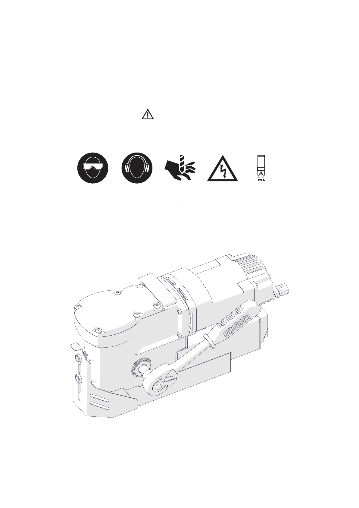
HOLEMAKER HMPRO36AD
Holemaker Portable Magnetic Drilling Machine
OPERATOR’S MANUAL
HOLEMAKER PRO 50
Holemaker Portable Magnetic Drilling Machine
OPERATOR’S MANUAL
WARNING!
BEFORE USE, ENSURE EVERYONE USING THIS MACHINE READS AND UNDERSTANDS
ALL SAFETY AND OPERATING INSTRUCTIONS IN THIS MANUAL .
HOLEMAKER PRO 50
BEWARE OF
ROTATING
MACHINE PARTS
LINE VOLTAGE
PRESENT
NEVER PLACE
FINGERS NEAR
CUTTING AREA OR
MACHINE ARBOR
HEARING PROTECTION
REQUIRED
EYE PROTECTION
REQUIRED
OPERATOR’S MANUAL
PRO 36
PRO 36
AD
AD
DRILLING MACHINE
WITH ELECTROMAGNETIC BASE
Holemaker Portable Magnetic Drilling Machine
OPERATOR’S MANUAL
WARNING!
BEFORE USE, ENSURE EVERYONE USING THIS MACHINE READS AND UNDERSTANDS
ALL SAFETY AND OPERATING INSTRUCTIONS IN THIS MANUAL .
EYE PROTECTION
REQUIRED
HEARING PROTECTION
REQUIRED
NEVER PLACE
FINGERS NEAR
CUTTING AREA OR
MACHINE ARBOR
LINE VOLTAGE
PRESENT
BEWARE OF
ROTATING
MACHINE PARTS
esahcruP fo etaD # laireS
Ver: 1.01 31/07/2018
Page 2

HMPRO36AD OPERATOR’S MANUAL
www.holemaker.com
LIMITED WARRANTY
Industrial Tool & Machinery Sales (hereinafter refered to as ITMS) will, within twelve (12)
months from the original date of purchase, repair or replace any goods found to be defective
in materials or workmanship.
This warranty is void if the item has been damaged by accident, neglect, improper service or
other causes not arising out of defects in materials or workmanship. This warranty does not
apply to machines and/or components which have been altered, changed, or modified in any
way, or subjected to overloading or use beyond recommended capacities and specifications.
Worn componentry due to normal wear and tear is not a warranty claim. Goods returned
defective shall be returned prepaid freight to ITMS or agreed repair agent, which shall be the
buyer’s sole and exclusive remedy for defective goods. ITMS accepts no additional liability
pursuant to this guarantee for the costs of travelling or transportation of the product or parts to
and from ITMS or the service agent or dealer, such costs are not included in this warranty.
Our goods come with guarantees which cannot be excluded under the Australian Consumer
Law. You are entitled to replacement or refund for a major failure and to compensation
for other reasonably foreseeable loss or damage. You are also entitled to have the goods
repaired or replaced if the goods fail to be of acceptable quality and the failure does not
amount to a major failure.
THE MANUFACTURER RESERVES THE RIGHT TO MAKE IMPROVEMENTS AND
MODIFICATIONS TO DESIGN WITHOUT PRIOR NOTICE.
PRODUCTS IMPORTED AND DISTRIBUTED NATIONALLY BY:
INDUSTRIAL TOOL & MACHINERY SALES
18 BUSINESS ST, YATALA QLD 4207
T: 07 3287 1114 E: [email protected]
F: 07 3287 1115 W: www.industrialtool.com.au
CONTENTS
1. GENERAL INFORMATION 3
1.1. Application 3
1.2. Technical data 3
1.3. Equipment included 4
1.4. Dimensions 5
1.5. Design 5
2. SAFETY PRECAUTIONS 6
3. STARTUP AND OPERATION 7
3.1. Installing and removing the handle 7
3.2. Installing, removing, and operating the annular cutter 8
3.3. Preparing 10
3.4. Drilling 12
3.5. Replacing the motor brushes 13
4. WIRING DIAGRAM 15
2
Page 3
HMPRO36AD OPERATOR’S MANUAL
www.holemaker.com
PRO 36 AD
1. GENERAL INFORMATION
1.1. Application
The PRO 36 AD is a drilling machine with electromagnetic base, designed to drill
holes with
diameters of up to 36 mm (1-7/16’’) either to a depth of up to 20 mm
(13/16’’) by using HSS annular cutters or to a depth of up to 30 mm (1-3/16’’) by using
TCT annular cutters. When using twist drill bits with a 19 mm (3/4’’) Weldon shank you
drill holes with diameters of up to 12 mm (1/2’’) to a depth of up to 20 mm
can
(13/16’’).
The electromagnetic base
allows the drilling machine to be fixed to ferromagnetic
surfaces with a force that ensures operator safety and proper machine operation.
A safety strap protects the machine from falling in case of a power loss.
With an optional HSS quill assembly you can drill holes to a depth of up to 25 mm
(1’’) by using HSS cutters or twist drill bits with a 19 mm Weldon shank.
1.2. Technical data
Voltage
Total power 1000 W
Motor power 920 W
Tool holder 19 mm (3/4’’) Weldon
Maximum drilling diameter with annular cutter 36 mm (1-7/16’’)
Maximum drilling diameter with twist drill bit 12 mm (1/2’’)
Maximum drilling depth with HSS cutter or drill bit 20 mm (13/16’’)*
Maximum drilling depth with TCT cutter 30 mm (1-3/16’’)
Electromagnetic base holding force
(surface with the thickness of 25 mm and roughness Ra = 1.25)
Electromagnetic base dimensions
Stroke 39 mm (1-1/2’’)
Rotational speed without load
Rotational speed under load
Minimum workpiece thickness 6 mm (1/4’’)
Protection class I
Noise level More than 85 dB
Required ambient temperature 0–40°C (32–104°F)
Weight 9.5 kg (21 lbs)
* Up to 25 mm (1’’) when used with an optional HSS quill assembly (ZSP-0521-04-00-00-0).
1~ 110–120 V, 50–60 Hz
1~ 220–240 V, 50–60 Hz
8 900 N
90 mm × 180 mm × 38.5 mm
3-9/16’’ × 7-1/16’’ × 1-1/2’’
550 rpm (for 115 V)
580 rpm (for 230 V)
350 rpm (for 115 V)
370 rpm (for 230 V)
3
Page 4
HMPRO36AD OPERATOR’S MANUAL
www.holemaker.com
PRO 36 AD
PRO 36 AD
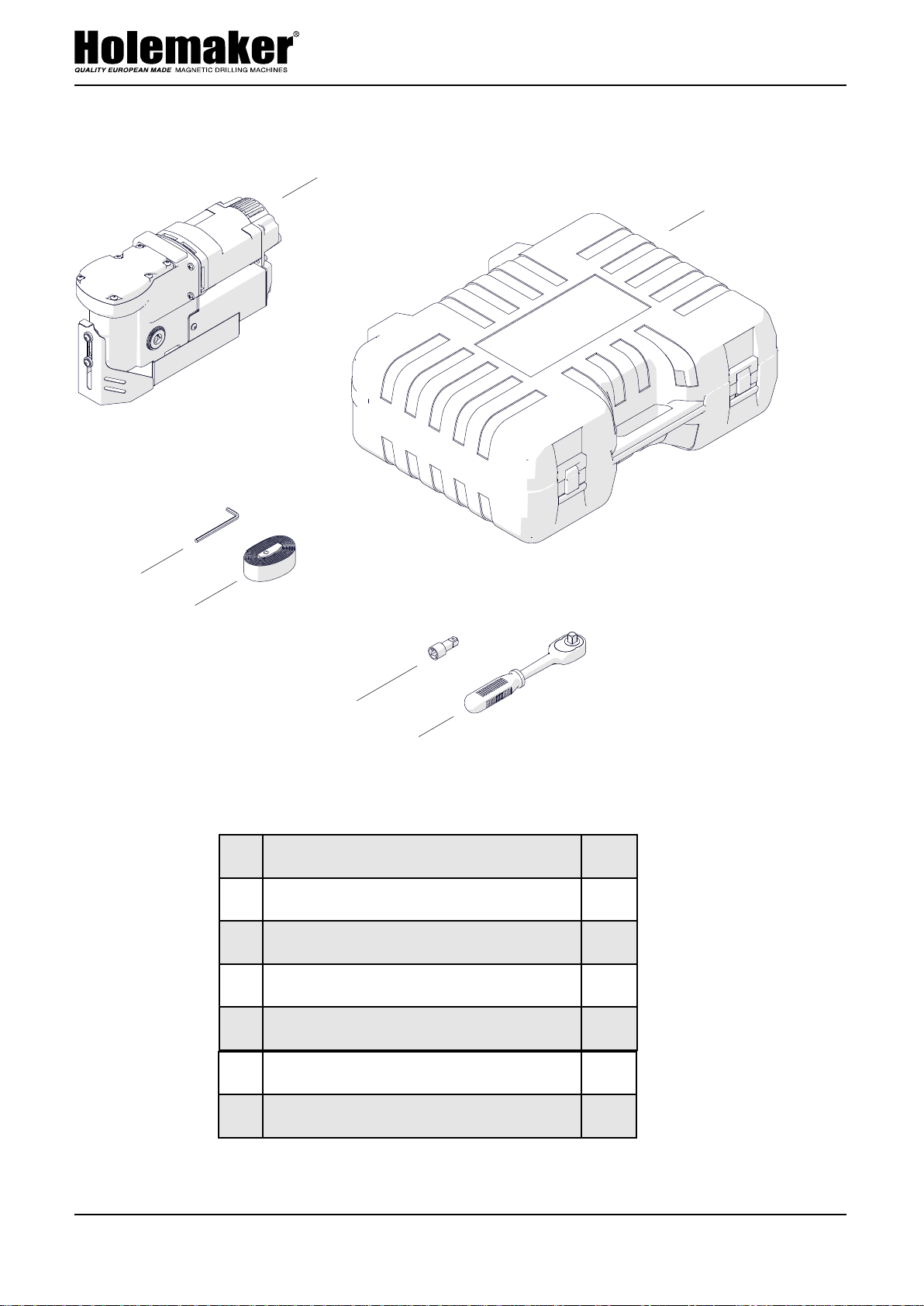
1.3. Equipment included
1
2
3
4
5
6
7
8
PRO 36 AD
1.3. Equipment included
1
2
3
4
5
6
7
8
PRO 36 AD
1.3. Equipment included
1 Drilling machine
1
unit
2 Plastic box
1
unit
3 Handle
1
unit
4 Handle adapter
1
unit
5 Pilot pin 7.98x85 for TCT cutters
1
unit
6 Pilot pin 6.34x74 for HSS cutters
1
unit
1
2
3
4
5
6
7
8
PRO 36 AD
1.3. Equipment included
1 Drilling machine
2 Plastic box
4
3 Handle
4 Handle adapter
7 Safety strap
8 4 mm hex wrench
– Operator’s Manual
1
unit
1
unit
1
unit
1
unit
1
unit
1
unit
1
unit
Page 5
HMPRO36AD OPERATOR’S MANUAL
www.holemaker.com
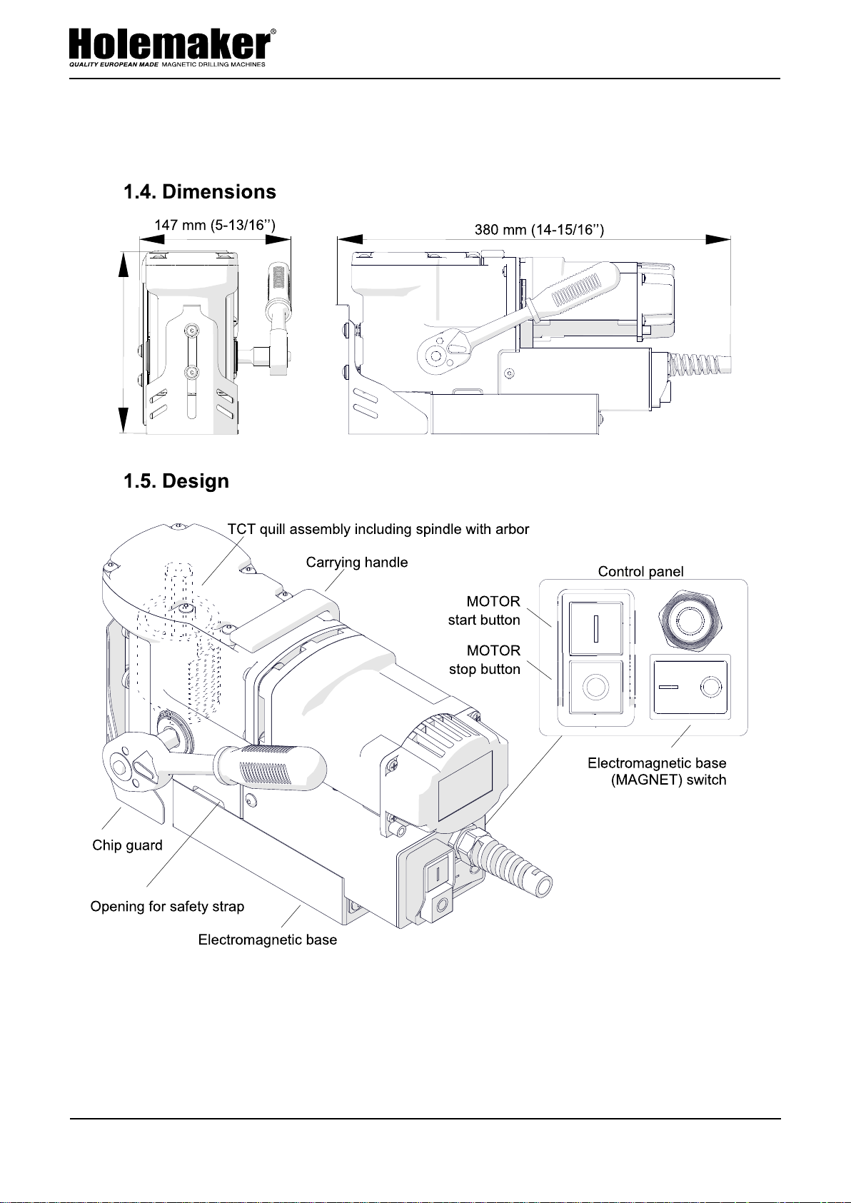
"
G
176 mm (6-15/16’’)
5
Page 6

HMPRO36AD OPERATOR’S MANUAL
www.holemaker.com
2. SAFETY PRECAUTIONS
CAUTION:
Drilling machine must not be used when:
1. The operator has not read the Operator’s Manual.
2. The work to be done is not in agreement with the recommendations in this Manual.
3. Drilling machine is not complete or has been repaired with non-original parts.
4. Power supply parameters do not conform to those stated on the motor’s plate.
5. Machines operator has not checked condition of the drilling machine, condition of air hose,
control panel or cutting tool.
6. Machine is not secured with safety chain as a protection from falling down especially when
used at heights or in vertical or upside-down positions.
7. Bystanders are present in the immediate vicinity of machine.
Important rules of safe use of drilling machine
1. Before attempting to work with the machine check condition of air hose and coupling.
2. Make sure that the drill is supplied with purified air and oiled.
3. Machine can be used outdoors, but is not weatherproof. Do not expose to rain, snow or
frost.
4. Machine should not be used on: rusty surfaces, steel plates covered with paint, uneven
surfaces, or steel plate which is being welded on.
5. Do not use the machine in explosion hazard zones.
6. Do not start work if the machine has excessive play on guide slides.
7. Always wear safety goggles and ear protection.
8. Do not remove metal chips with bare hands, always use gloves.
9. Do not touch the spindle and cutting tool during work.
10. Cutting Tools must be fastened firmly.
11. Do not drill with blunt of damaged cutting tools.
12. Do not use annular cutters without a pilot pin, and arbors without an ejection spring.
Do not touch or replace the cutting tool with power source on
13. After use, always clean drilling machine from metal chips and cutting fluid.
14. Any maintenance and repair should be performed only when the machine is disconnected
from the air supply.
15. Before each use the machine should be checked for the presence of damage. Check
whether any of the parts are broken and all the that all parts are fasten properly.
16. In the case that the machine falls on a hard surface, from a height, is wet or is subjected
to other unfortunate events that could affect its technical state - work should be terminated
immediately and the machine should be sent to service for inspection as soon as possible.
This machine is not recommended to be used to drill on steel thinner than 10mm (3/8”).
On thin steel less than 10mm (3/8”) magnet’s adhesive power would be significantly
reduced which can cause machines failure or personal injury.
6
Page 7
HMPRO36AD OPERATOR’S MANUAL
www.holemaker.com
PRO 36 AD
3. STARTUP AND OPERATION
3.1. Installing and removing the handle
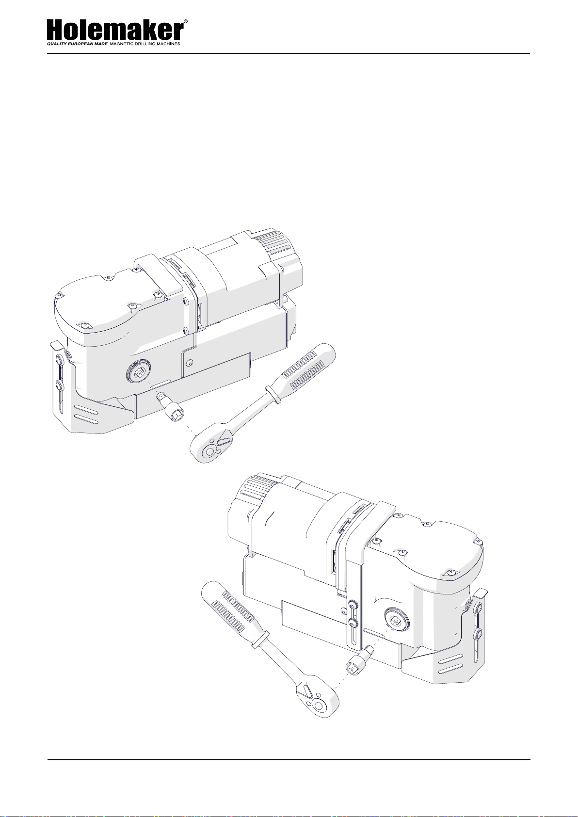
Install the handle by using the adapter as shown in Fig. 1. The handle can be installed
from the opposite side of the machine to allow working in places hard to reach or
using the machine by a left-handed person.
To remove the handle, pull it out.
Fig. 1. Installing the handle
7
Page 8
HMPRO36AD OPERATOR’S MANUAL
www.holemaker.com
PRO 36 AD
3.2. Installing, removing, and operating the annular cutter
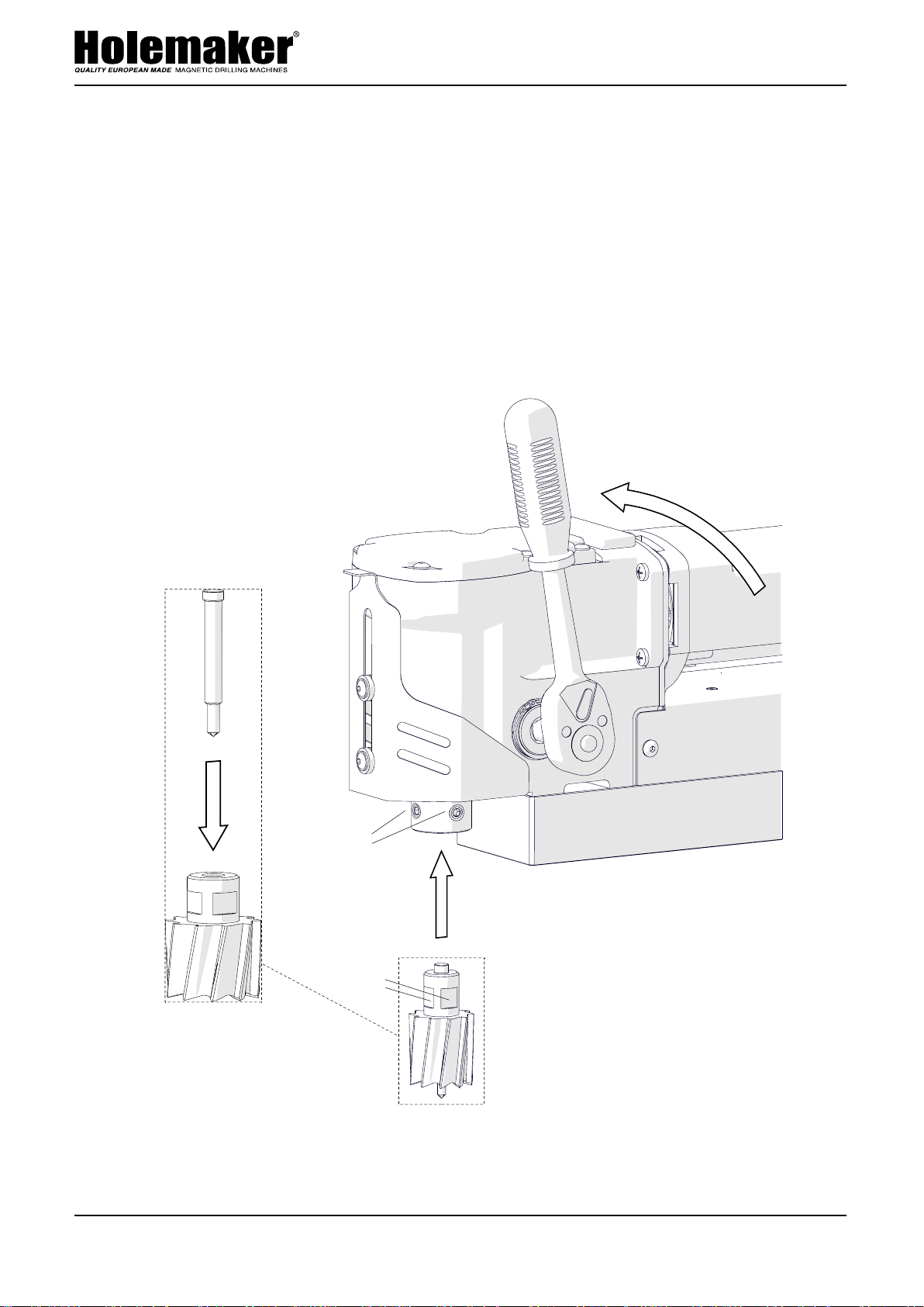
Unplug the machine from the power source, raise the chip guard, and then rotate the
handle to the left (1, Fig. 2) to access the set screws (2). Next, wear protective gloves,
insert the required pilot pin into the annular cutter (3), and then use a clean and dry
cloth to wipe the arbor and cutter. Next, place the cutter into the arbor (4) so that the
flats (5) are aligned with the set screws (2), and then use the 4 mm hex wrench to
tighten both set screws.
To remove the cutter, loosen the screws (2) with the 4 mm hex wrench.
1
3
2
4
5
Fig. 2. Installing the annular cutter
8
Page 9
HMPRO36AD OPERATOR’S MANUAL
www.holemaker.com
PRO 36 AD
Fig.
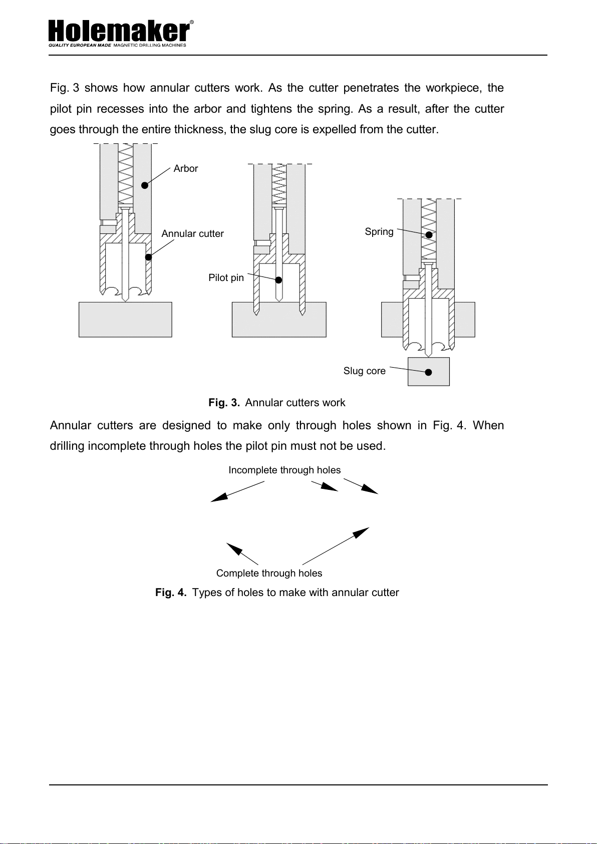
3 shows how annular cutters work. As the cutter penetrates the workpiece, the
pilot pin recesses into the arbor and tightens the spring. As a result, after the cutter
goes
through the entire thickness, the slug core is expelled from the cutter.
Fig. 3. Annular cutters work
Annular cutters are designed to make only through holes shown in Fig. 4. When
drilling incomplete through holes the pilot pin must not be used.
Fig. 4. Types of holes to make with annular cutter
Slug core
Spring
Pilot pin
Annular cutter
Arbor
Incomplete through holes
Complete through holes
9
Page 10

HMPRO36AD OPERATOR’S MANUAL
www.holemaker.com
PRO 36 AD
3.3. Preparing
Before starting, clean steel parts, including the arbor, from anti-corrosion coating
used to preserve the machine for storage and transport.
Install the handle as described before.
Based on the hole size desired, select the proper annular cutter or drill bit with a
19 mm Weldon shank. Next, use a clean and dry cloth to wipe the arbor and cutter
(drill bit), and then install the cutter (drill bit) into the arbor as described before.
Position the machine on a flat ferromagnetic surface with a thickness of at least
6 mm (1/4’’). The workpiece must be clean, without rust or paint that decrease the
holding force. The force value depends also on the type, thickness, flatness, and
roughness of the surface, fluctuations of the supply voltage, and the wear of the
electromagnetic base bottom. Some types of steel are non-ferromagnetic (do not
conduct magnetic flux) and the machine is not capable to clamp onto them.
Connect the machine to the power source, and set the MAGNET switch to ‘I’ to
turn on the clamping of the electromagnetic base.
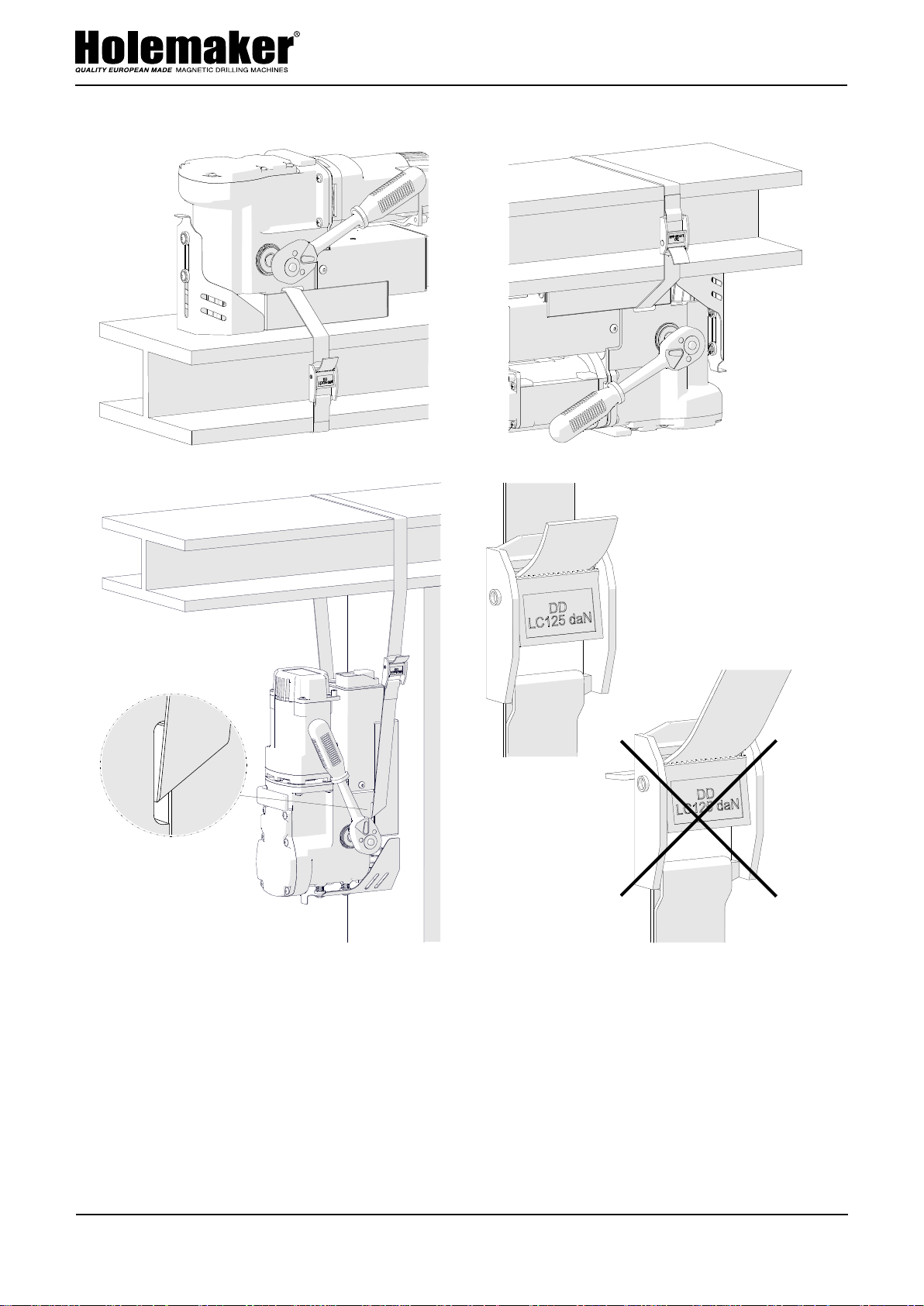
Use the safety strap to prevent the machine from falling and avoid possible injury
to the operator if the machine loses magnetic clamping in case of a power loss. To
protect the machine, insert the strap through the opening in the machine body and
attach the machine to a fixed structure. The strap must be tight, not twisted (except
standard twist for horizontal drilling from Fig. 5c), and must be replaced every single
time the machine hangs on the strap as a result of coming loose from steel. Never
insert the strap into the buckle from the front (Fig. 5d).
10
Page 11
HMPRO36AD OPERATOR’S MANUAL
www.holemaker.com
PRO 36 AD
a)
b)
c)
Horizontal drilling
Maximum possible
twist of the strap
Vertical drilling
Inverted drilling
d)
CORRECT
✓
INCORRECT
Fig. 5. Protecting the machine from falling by using the safety strap
Rotate the handle to the left to place the pilot pin (drill bit) above the workpiece.
Fill the coolant bottle (not included) with a cutting fluid. Do not use pure water as
the cutting fluid. However, using emulsions formed from mixing water and drilling oil
is satisfactory.
When drilling in vertical positions (Fig. 5a), apply
drilling
area. When drilling in inverted or horizontal positions (Fig. 5b, 5c) use coolants
the coolant manually into the
under pressure or in the form of spray or paste.
11
Page 12

HMPRO36AD OPERATOR’S MANUAL
www.holemaker.com
PRO 36 AD
3.4. Drilling
Start the motor with the green MOTOR button, and slowly rotate the handle to the left
to lower the tool to the workpiece, and start drilling.
When using annular cutter, drill holes in one pass.
When the annular cutter goes through the workpiece, the slug
core is expelled from the cutter with a significant force.
When using drill bits, drill holes with diameters of
passes. Drill a first hole by using a drill bit with the 70% diameter of the hole size
desired, and then drill again by using a bit with the diameter equal to the hole size
desired.
After the hole is made, retract the tool from the workpiece and press the red
MOTOR button to stop the motor. Before moving the machine to another drilling spot,
set the MAGNET switch to ‘O’ to turn off the electromagnetic base.
After the work is finished, unplug the machine from the power source, clean
chips and excess coolant from the machine and tool, and then remove the machine
from the worksite.
8–12 mm (5/16’’ – 1/2’’) in two
Before inserting the machine into the box, remove the handle, and then wear
gloves to remove the tool from the holder.
12
Page 13
HMPRO36AD OPERATOR’S MANUAL
www.holemaker.com
PRO 36 AD
3.5. Replacing the motor brushes
Check the condition of the carbon brushes every 100 work hours. To do this, unplug the
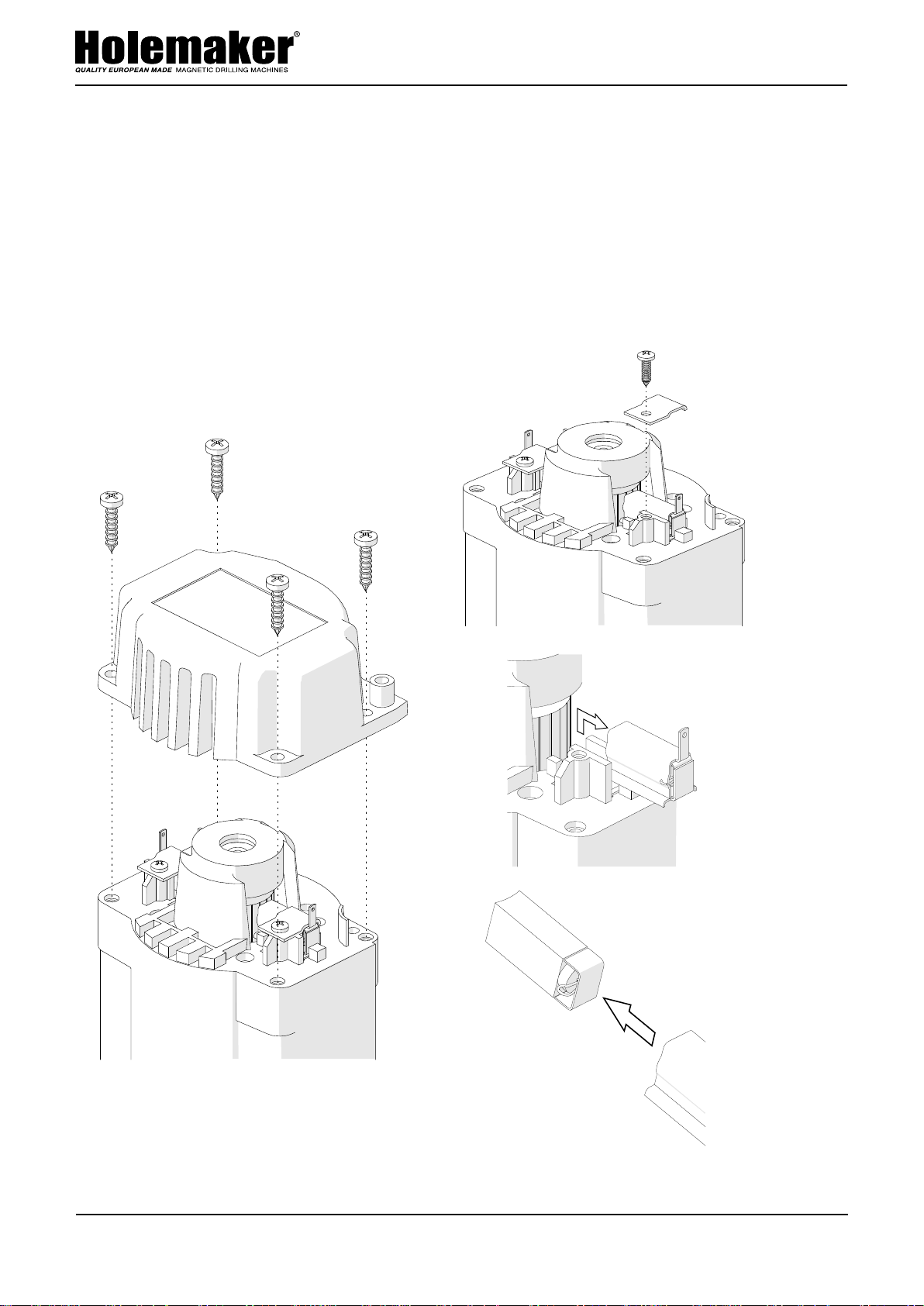
machine from the power source, and unscrew the cover (1, Fig. 6). Next, unscrew the
pressing plate (2), and then remove the brush holder (3) and the brush (4). If the
length of the brush is less than 5 mm (3/16’’), replace both brushes with new ones.
To install brushes, proceed in reverse order. After the replacement, run the motor
without load for 20 minutes.
2
1
3
4
Fig. 6. Replacing the brushes
13
Page 14
HMPRO36AD OPERATOR’S MANUAL
www.holemaker.com
PRO 36 AD
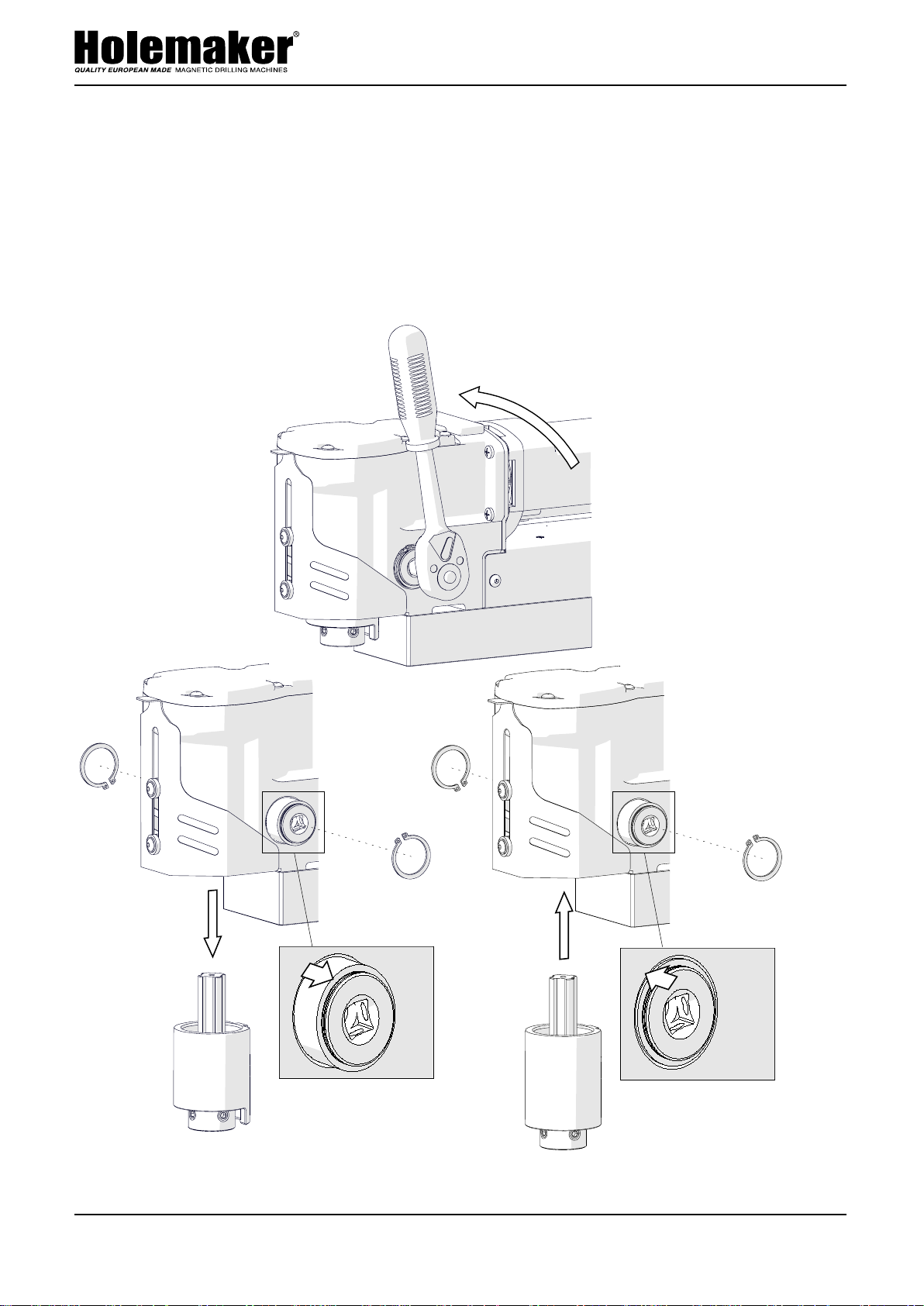
To install the assembly, unplug the machine from the power source, raise the cover,
and then rotate the handle to the left (1, Fig. 7) to lower the standard TCT quill
assembly as much
as possible. Next, remove the handle, use pliers to remove the
retaining rings (2), and then push out the shaft (3) by 16 mm (10/16’’), which will expel
the TCT quill assembly (4). Insert the HSS quill assembly (5), push in the shaft (6), and
then place the retaining rings back in place (7).
1
14
2
2
4
3
Fig. 7. Installing the HSS quill assembly
7
7
5
6
Page 15

HMPRO36AD OPERATOR’S MANUAL
www.holemaker.com
PRO 36 AD
5. WIRING DIAGRAM
PRO 36 AD
5. WIRING DIAGRAM
15
Page 16
HMPRO36AD OPERATOR’S MANUAL
www.holemaker.com
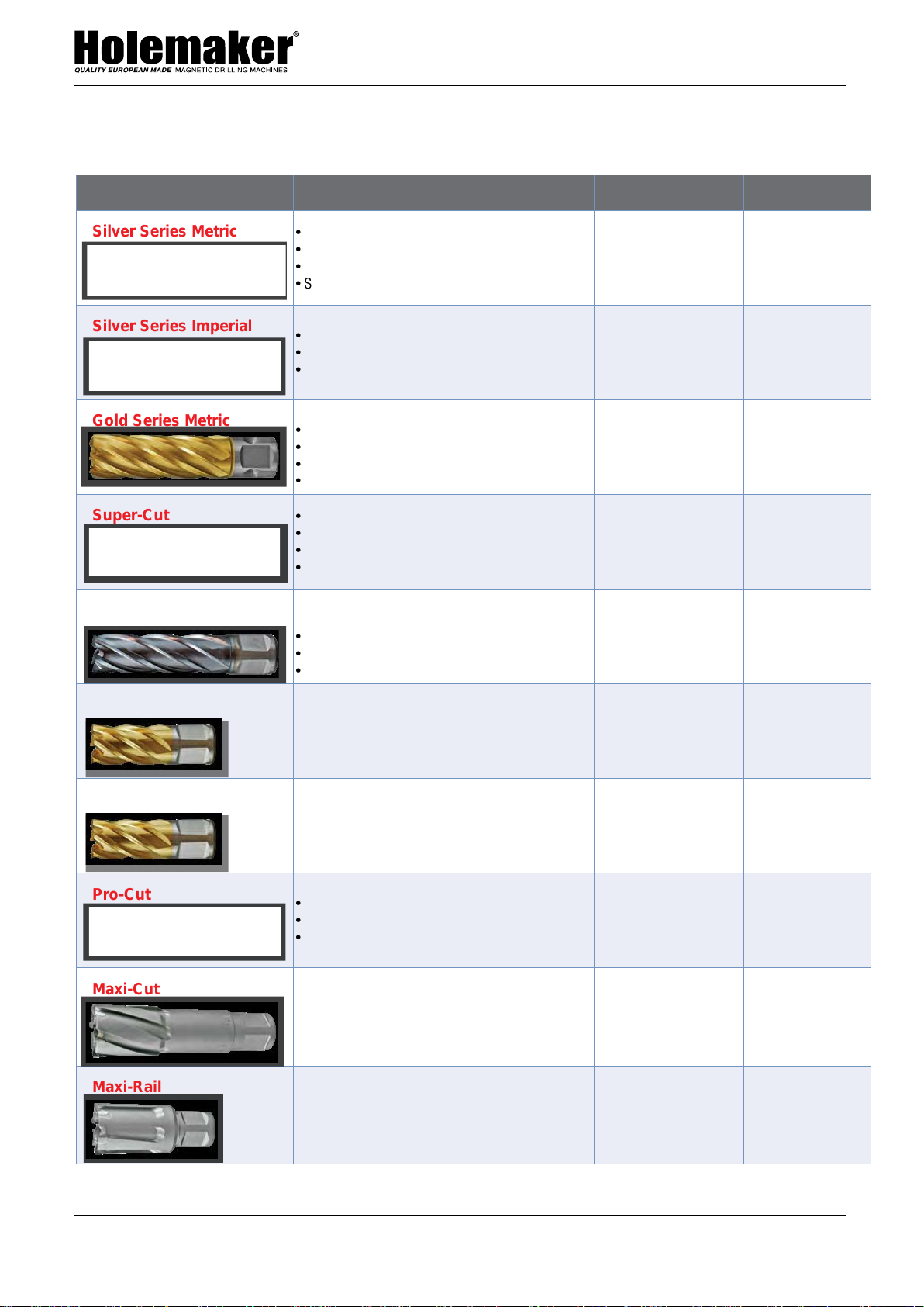
HOLEMAKER ANNULAR CUTTER GUIDE
Cutter Type Features Diameter Available Cut Depth Available Applications
Silver Series Metric
Silver Series Imperial
Gold Series Metric
Super-Cut
Super-Cut TICN
• M2AL High Speed Steel
• Universal Shank
• Multi-Cut Geometry
• Step Hardened
• M2AL High Speed Steel
• Multi-Cut Geometry
• Step Hardened
• M2AL High Speed Steel
• Titanium Nitride Coated
• Universal Shank
• Multi-Cut Geometry
• Step Hardened
• Made In U.S.A
• Highest Quality
• M2 High Speed Steel
• Multi-Cut Geometry
• Titanium Carbon
Nitride Coated
• Made In U.S.A
• M2 High Speed Steel
• Multi-Cut Geometry
• 12 to 60mm Metric • 25mm & 50mm • General Purpose
• 7/16" to 2-1/4" Imperial • 1", 2" & 3" • General Purpose
• 12 to 60mm Metric • 25mm, 50mm & 75mm • General Purpose
• 12 to 60mm Metric
• 7/16" to 2-1/2" Imperial
• 12 to 32mm Metric • 25mm & 50mm
• 25mm, 50mm & 75mm
• 1", 2" & 3"
• General Purpose
• Stainless Steel
• Cast Iron
Super-Cut M42 Cobalt
Super-Cut M42 Chassis
Pro-Cut
Maxi-Cut
Maxi-Rail
• M42 High Speed Steel
• 8% Cobalt
• Titanium Nitride Coated
• Made In U.S.A
• Multi-Cut Geometry
• Stack Ground Geometry
• M42 High Speed Steel
• 8% Cobalt
• Titanium Nitride Coated
• Made In U.S.A
• ASP Powder Steel
• Multi-Cut Geometry
• Incredible Performance
• Tungsten Carbide Tipped
• Increased Resistance
to Breakage
• Multi-Cut Geometry
• Tungsten Carbide Tipped
• Increased Resistance
To Breakage
• Multi-Cut Geometry
• 1/2" to 1" Imperial • 1"
• 1/2" to 1" Imperial • 1"
• 12 to 22mm Metric • 25mm & 50mm
• 14 to 150mm Metric
• 5/8" to 2-3/8" Imperial
• 18 to 35mm Metric • 25mm
• 50mm, 75mm
& 100mm
• Truck Chassis
• Hardened Steels
• Truck Chassis
• Multi-Layered Steel
• Rail Line
• Hard Materials
• Stainless Steel
• Wear Plate
• Large Diameters
• Stainless Steel
• Hard Materials
• Wear Plate
• Rail Line
• Hard Materials
• Wear Plate
16
Page 17
HM PRO 36 AD
1
6
2
5
4
3
1
6
2
5
4
3
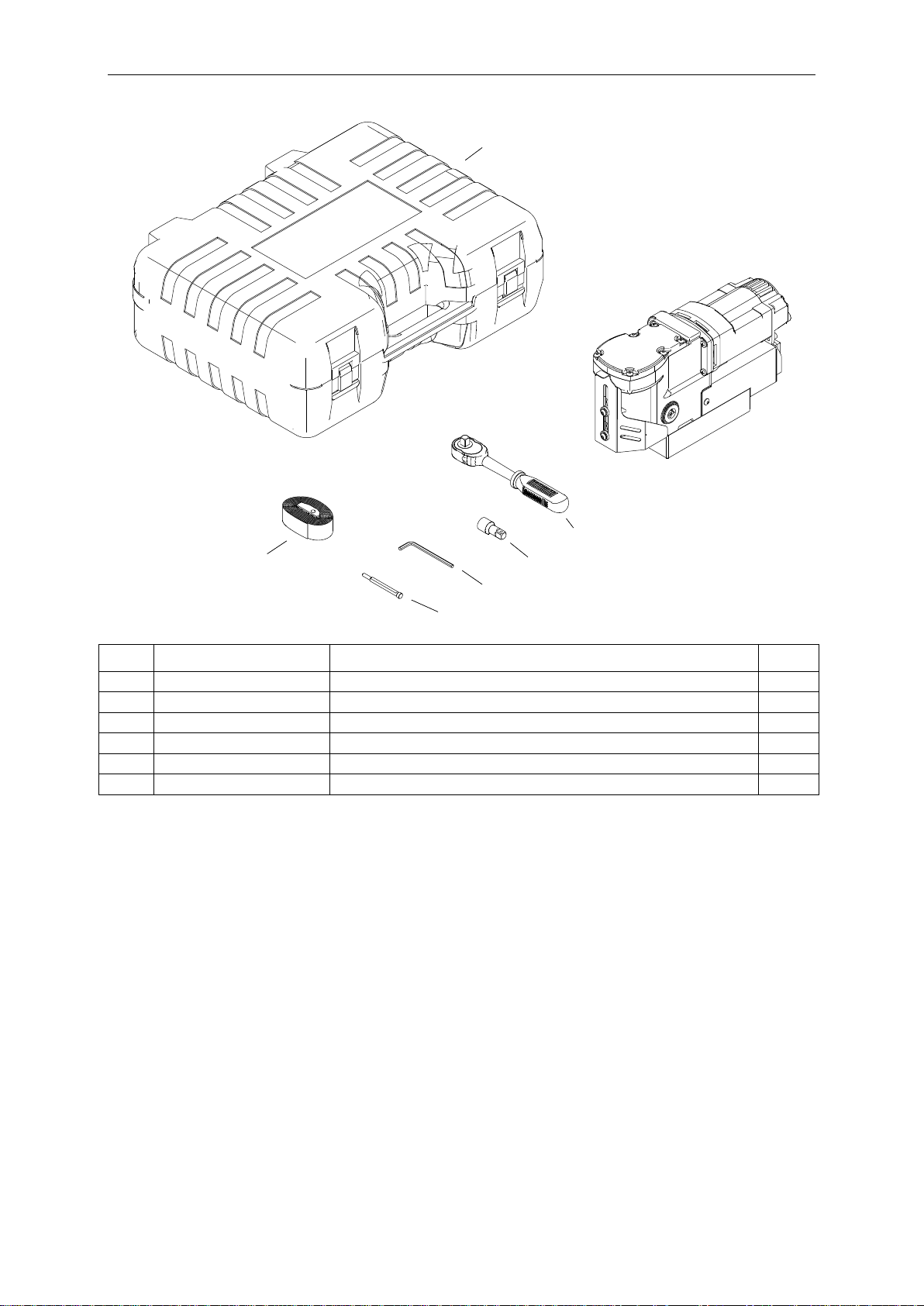
ITEM
PART NUMBER
DESCRIPTION
Q-TY
1
SKR-000012
PLASTIC BOX
1
2
PAS-000007
SAFETY STRAP 250
1
3
PLT-0378-15-00-00-0
PILOT PIN
1
4
KLC-000007
4 MM HEX WRENCH
1
5
PRD-000002
TORQUE STICK
1
6
KLC-000048
RATCHET WRENCH 3-8
1
Page 18
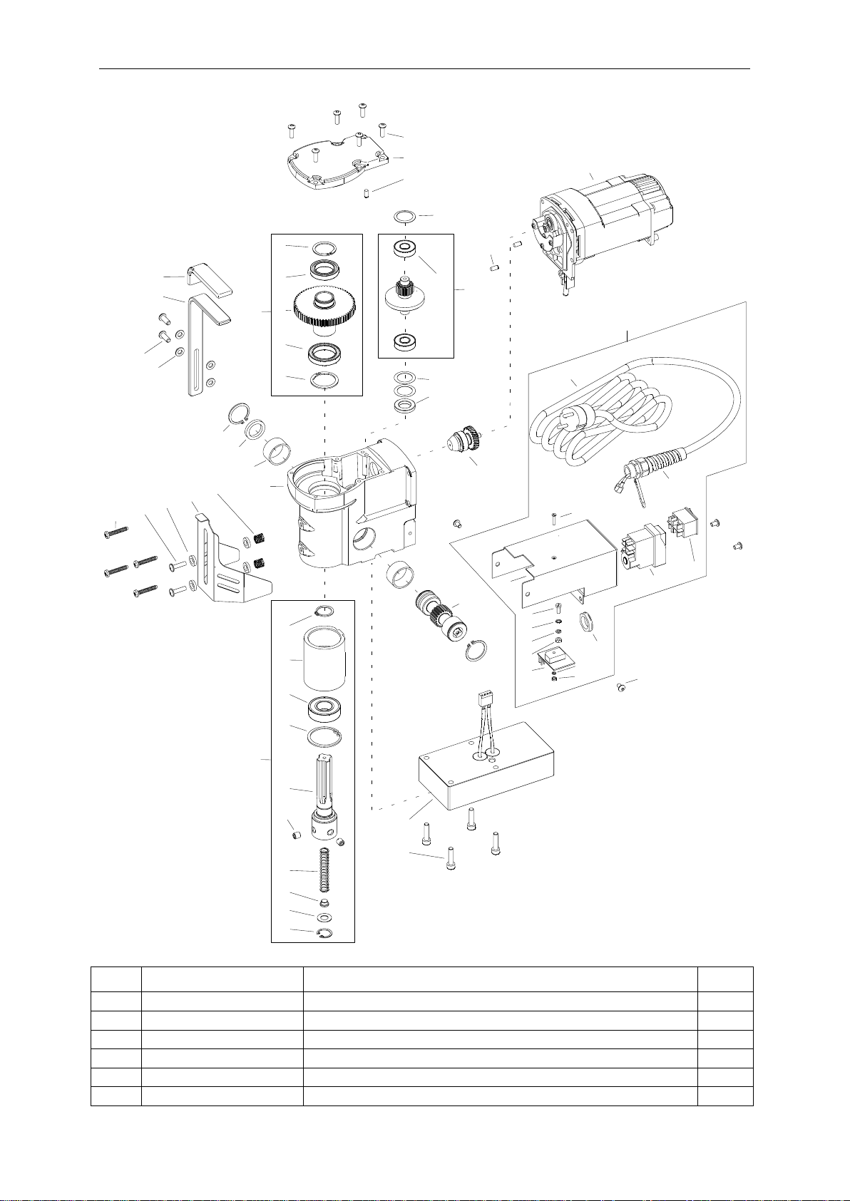
HM PRO 36 AD
52
53
54
55
49
4
25
26
42
45
18
19
40
39
51
57
59
38
50
17
48
44
37
41
56
46
30
36
16
35
20
34
21
47
33
22
32
31
43
58
23
15
14
29
13
28
27
3
24
9
8
7
12
11
10
3
6
5
2
1
ITEM
PART NUMBER
DESCRIPTION
Q-TY
1
WKR-000098
HEX SOCKET BUTTON HEAD SCREW M5x16
6
2
PKR-0521-02-00-00-1
GEARBOX COVER
1
3
KLK-000044
DOWEL PIN 5n6x10
3
4
KOL-0521-08-00-00-0
GEAR z63 ASSY
1
5
PRS-000223
EXTERNAL RETAINING RING 25z TYPE A
1
6
LOZ-000169
BALL BEARING 25x42x9
1
Page 19

HM PRO 36 AD
ITEM
PART NUMBER
DESCRIPTION
Q-TY
7
KOL-0521-08-01-00-0
GEAR z63
1
8
LOZ-000100
BALL BEARING 30x42x7
1
9
PRS-000021
EXTERNAL RETAINING RING 30z TYPE A
1
10
SPR-000063
DISC SPRING fi27.99xfi21.74x0.3
1
11
WLK-0521-07-00-00-0
PINION SHAFT z16 z32 ASSY
1
12
LOZ-000038
BALL BEARING 12x28x8
2
13
PDK-000221
WASHER 20x28x0.1
2
14
PDK-0521-13-00-00-0
SETTING WASHER
1
15
SLN-0521-03-00-00-1
MOTOR ASSY - 120V
1
15
SLN-0521-03-00-00-3
MOTOR ASSY - 230V
1
16
NSD-000009
HANDLE COVER
1
17
UCW-0521-12-00-00-0
HANDLE
1
18
WKR-000101
HEX SOCKET BUTTON HEAD SCREW M6x16
2
19
PDK-000021
ROUND WASHER 6.4
4
20
PRS-000019
EXTERNAL RETAINING RING 28z
2
21
PRS-000259
SEAL 20x28x4
1
22
TLJ-000010
SELF-LUBRICATING SLEEVE 28.05x32x1
2
23
KRP-0521-01-01-00-1
BODY
1
24
WLK-0521-10-00-00-0
FEED SHAFT z20
1
25
WKR-000302
SELF-TAPPING SCREW 5x30
4
26
WKR-000395
HEX SOCKET ROUND HEAD SCREW WITH FLANGE M5x20
2
27
PDK-000151
NYLON WASHER 8.1x14x3
4
28
OSL-0521-09-01-00-0
CHIP GUARD
1
29
SPR-000030
SPRING 1x10x17.5
2
30
ZSP-0521-04-00-00-0
QUILL ASSY
1
31
PRS-000011
EXTERNAL RETAINING RING 20z
1
32
TLJ-0521-04-01-00-0
QUILL CARRIER
1
33
LOZ-000045
BALL BEARING 20x42x12
1
34
PRS-000026
INTERNAL RETAINING RING 42w
1
35
WRZ-0378-03-02-00-0
SPINDLE
1
36
WKR-000063
HEX SOCKET SET SCREW WITH FLAT POINT M8x8
2
37
SPR-0378-03-04-00-0
SPRING
1
38
WYP-0378-03-05-00-0
PLUNGER
1
39
PDK-0139-00-04-00-0
WASHER 18.8x10x1
1
40
PRS-000009
INTERNAL RETAINING RING 19w
1
41
PDS-0521-14-00-00-0
ELECTROMAGNETIC BASE ASSY
1
42
LOZ-000072
BALL BEARING 9x26x8
1
43
WLK-0521-06-00-00-0
PINION SHAFT z11 z26 ASSY
1
44
STR-0521-05-00-00-0
ELECTRONIC CONTROLLER ASSY – 120V
1
44
STR-0521-05-00-01-0
ELECTRONIC CONTROLLER ASSY – 230V (CEE)
1
44
STR-0521-05-00-02-0
ELECTRONIC CONTROLLER ASSY – 230V (AU)
1
44
STR-0521-05-00-03-0
ELECTRONIC CONTROLLER ASSY – 230V (INDIA)
1
45
SZN-0075-00-51-00-5
POWER CORD 120V 3x2.08 WITH STRAIN RELIEF ASSY (US)
1
45
SZN-0212-10-02-00-2
POWER CORD 230V 3x1.5 WITH STRAIN RELIEF ASSY (CEE)
1
45
SZN-0212-10-02-00-1
POWER CORD 230V 3x1 WITH STRAIN RELIEF ASSY (AU)
1
45
PWD-0212-10-02-00-6
POWER CORD 230V 3x1.5 WITH STRAIN RELIEF ASSY (INDIA)
1
46
DLW-000007
CABLE GLAND WITH STRAIN RELIEF PG11
1
47
WKR-000420
COUNTERSUNK HEAD SCREW M3x16
1
48
OBD-0521-05-01-00-0
ELECTRONIC CONTROLLER HOUSING
1
49
WKR-000208
PAN HEAD SCREW M4x10
1
50
PDK-000060
EXTERNAL TOOTH LOCK WASHER 4.3
1
51
NKR-000013
HEX NUT M4
1
Page 20

HM PRO 36 AD
ITEM
PART NUMBER
DESCRIPTION
Q-TY
52
MDL-0378-14-04-00-4
ELECTRONIC MODULE SW=35A - 230V
1
52
MDL-0378-14-04-00-3
ELECTRONIC MODULE SW=35A - 120V
1
53
PDK-000041
SPRING WASHER 3.1
1
54
NKR-000009
HEX NUT M3
1
55
NKR-000040
STRAIN RELIEF NUT
1
56
WLC-000006
START-STOP SWITCH - 120V
1
56
WLC-000008
START-STOP SWITCH - 230V
1
57
PNK-000013
POWER SWITCH
1
58
WKR-000289
HEX SOCKET BUTTON HEAD SCREW M5x8
4
59
PDK-000043
SPRING WASHER 4.1
1
Page 21
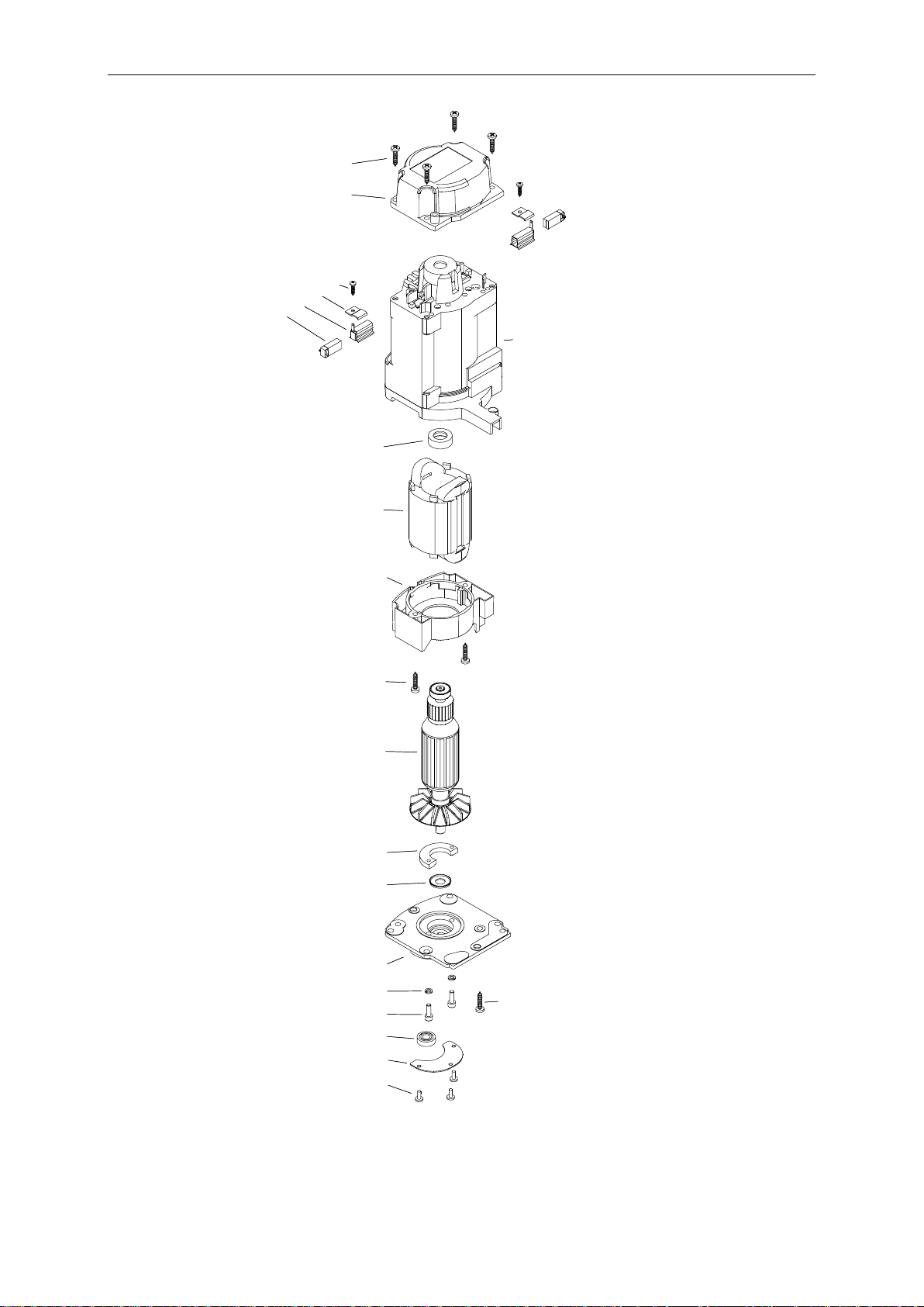
HM PRO 36 AD
17
21
20
19
18
16
15
4
14
13
12
11
10
9
8
7
5
2
3
6
1
17
21
20
19
18
16
15
4
14
13
12
11
10
9
8
7
5
2
3
6
1
Page 22

HM PRO 36 AD
ITEM
PART NUMBER
DESCRIPTION
Q-TY
1
WKR-000241
SELF-TAPPING SCREW 4x20
4
2
PKR-0440-03-02-00-0
MOTOR COVER
1
3
WKR-000359
SCREW 3x13
2
4
PLY-0271-03-07-00-0
BRUSH HOLDER PRESSURE PLATE
2
5
SCT-0271-03-06-00-0
BRUSH HOLDER
2
6
SCZ-000008
MOTOR BRUSH 6x9x17
2
7
OBD-0272-03-01-01-1
STATOR HOUSING
1
8
WKL-000001
BEARING INSERT 19x7.5
1
9
STN-000002
STATOR – 120V
1
9
STN-000004
STATOR – 220V
1
10
OSL-0271-03-01-02-0
FAN GUARD
1
11
WKR-000241
SELF-TAPPING SCREW 4x20
2
12
WRN-000016
ROTOR – 120V
1
12
WRN-000017
ROTOR – 230V
1
13
PRS-0271-03-02-02-1
GEARBOX COVER RING
1
14
USZ-000055
SEAL 1 15
PKR-0521-03-01-01-1
MOTOR COVER
1
16
PDK-000042
SPRING WASHER 4.1
2
17
SRB-000062
HEX SOCKET HEAD CAP SCREW M4x12
2
18
WKR-000236
SELF-TAPPING SCREW 5x16
1
19
LOZ-000061
BALL BEARING 7x17x5
1
20
OSL-0521-03-02-00-0
GEAR COVER
1
21
WKR-000182
CROSS RECESSED PAN HEAD SCREW M3x8
3
 Loading...