

Page 1
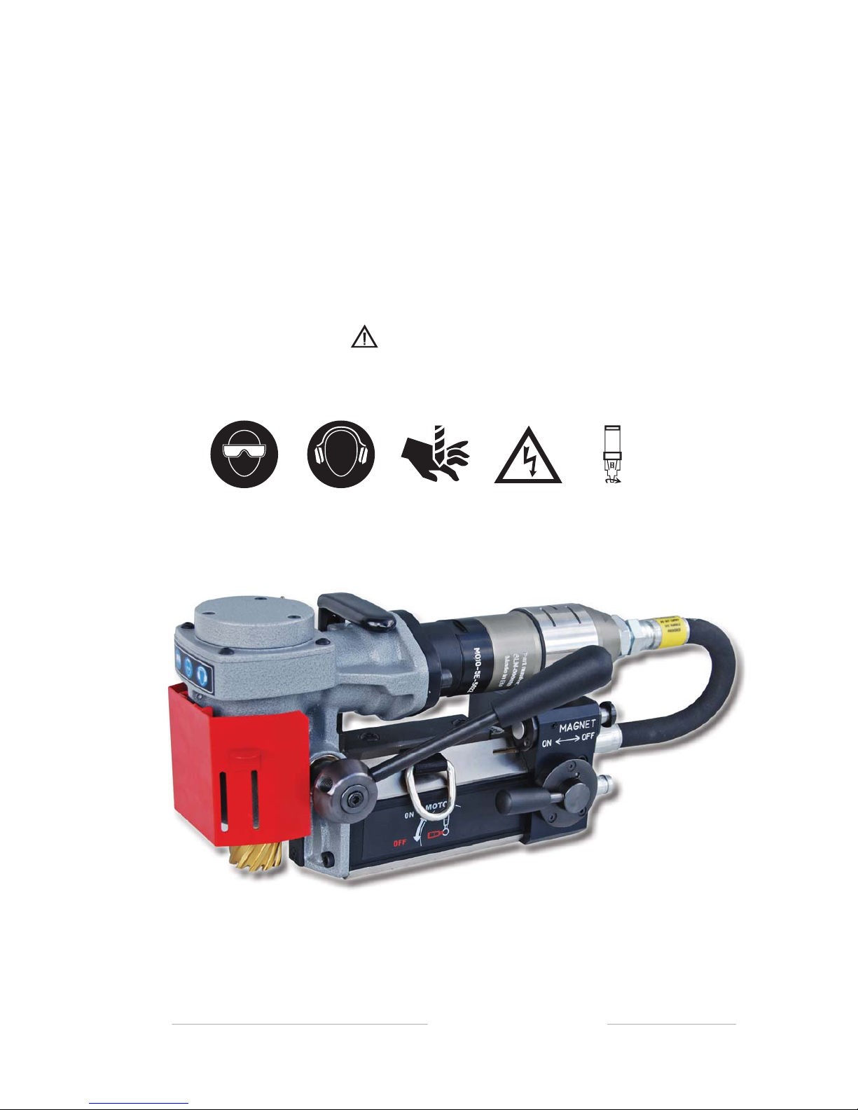
Holemaker Portable Magnetic Drilling Machine
OPERATOR’S MANUAL
WARNING!
BEFORE USE, ENSURE EVERYONE USING THIS MACHINE READS AND UNDERSTANDS
ALL SAFETY AND OPERATING INSTRUCTIONS IN THIS MANUAL .
esahcruPfoetaD#laireS
HOLEMAKER 35
PNEUMATIC
BEWARE OF
ROTATING
MACHINE PARTS
LINE VOLTAGE
PRESENT
NEVER PLACE
FINGERS NEAR
CUTTING AREA OR
MACHINE ARBOR
HEARING PROTECTION
REQUIRED
EYE PROTECTION
REQUIRED
Page 2

Holemaker 35 Pneumatic Magnetic Drilling Machine
Congratulations on the purchase of your Holemaker 35 Pneumatic magnetic drilling machine.
Holemaker drilling machines are designed to deliver fast, efficient hole drilling performance in portable applications.
TABLE OF CONTENTS
Important Safety Instructions . . . . . . . . . . . . . . . . . . . . . . . . . . . . . . . . . . .3 - 4
Special Instructions . . . . . . . . . . . . . . . . . . . . . . . . . . . . . . . . . . . . . . . . . . . .6
Technical Data . . . . . . . . . . . . . . . . . . . . . . . . . . . . . . . . . . . . . . . . . . . . . . . . . 5
Contents of Package . . . . . . . . . . . . . . . . . . . . . . . . . . . . . . . . . . . . . . . . . . .6
Machine Operation . . . . . . . . . . . . . . . . . . . . . . . . . . . . . . . . . . . . . . . . . .6 - 8
Basic Troubleshooting . . . . . . . . . . . . . . . . . . . . . . . . . . . . . . . . . . . . . . . . .10
Maintenance and Service . . . . . . . . . . . . . . . . . . . . . . . . . . . . . . . . . . . . . . .9
Machine Parts Breakdown. . . . . . . . . . . . . . . . . . . . . . . . . . . . . . . . . . . 11 - 20
LIMITED WARRANTY
Industrial Tool & Machinery Sales (hereinafter refered to as ITMS) will, within twelve (12) months from the original
date of purchase, repair or replace any goods found to be defective in materials or workmanship.
This warranty is void if the item has been damaged by accident, neglect, improper service or other causes not
arising out of defects in materials or workmanship. This warranty does not apply to machines and/or components
which have been altered, changed, or modified in any way, or subjected to overloading or use beyond recommended
capacities and specifications. Worn componentry due to normal wear and tear is not a warranty claim. Goods returned
defective shall be returned prepaid freight to ITMS or agreed repair agent, which shall be the buyer’s sole and exclusive
remedy for defective goods. ITMS accepts no additional liability pursuant to this guarantee for the costs of travelling
or transportation of the product or parts to and from ITMS or the service agent or dealer, such costs are not included
in this warranty.
THE MANUFACTURER RESERVES THE RIGHT TO MAKE
Imported And Distributed By
INDUSTRIAL TOOL & MACHINERY SALES
18 BUSINESS ST, YATALA, QLD AUSTRALIA 4207
PHONE 07 3287 1114 FAX 07 3287 1115
[email protected] www.industrialtool.com.au
IMPROVEMENTS AND MODIFICATIONS TO DESIGN WITHOUT PRIOR NOTICE.
2
Page 3

IMPORTANT SAFETY INSTRUCTIONS
WARNING!
READ AND SAVE ALL INSTRUCTIONS FOR FUTURE REFERENCE.
1. Keep Work Area Clean
3. Check the state of the air lines, connections and machine before beginning operation
4. Ensure the drill is powered by cleaned and oiled air
5. Do not allow the drill to be submerged in water, or exposed to moisture
• Cluttered areas and benches increase risk of injuries.
2. Consider Work Area Environment
• Keep work area well lit.
• Do not use tool in presence of flammable liquids or gases.
6. Keep Children Away
• Do not let visitors contact tool or air supply
• All visitors should be kept away from work area.
7. Store Idle Tools
• When not in use, tools should be stored in a dry, high and locked-up place, out of reach of children.
8. Do Not Force Tool
• It will do the job better and safer at the rate for which it was intended.
9. Use Right Tool
• Do not force a small tool or attachment to do the job of a heavy-duty tool.
• Do not use tool for unintended purpose. For example: Do not use a circular saw for cutting tree limbs or logs.
10. Dress Properly
• Do not wear loose clothing or jewellery. They can be caught in moving parts.
• Rubber gloves and non-skid footwear are recommended when working outdoors.
• Wear protective hair covering to contain long hair.
• Always wear safety glasses
• Use face or dust mask if necessary
• Use hearing protection
11. Do Not Abuse Tool
• Never carry tool the air hose
• Keep tool and air supply hose away from heat, oil and sharp edges.
12. Do Not Overreach
• Keep proper footing and balance at all times.
3
Page 4
12. Maintain Tools With Care
• Keep tools sharp and clean for better and safer performance.
• Follow instructions for lubricating and changing accessories.
• Inspect tool periodically and if damaged, have repaired by authorized service facility.
• Inspect air supply hose periodically and replace if damaged.
• Keep handles dry, clean, and free from oil and grease.
13. Disconnect Tools
• Unplug from air supply when not in use, before servicing, and when changing accessories, such as cutters.
14. Remove Adjusting Keys And Wrenches
• Form habit of checking to see that keys and adjusting wrenches are removed from tool before turning it on.
15. Avoid Unintentional Starting
• Do not carry a plugged-in tool. Always disconnect from air supply before moving.
• Be sure switches are off before connecting to the air supply
16. Stay Alert
• Watch
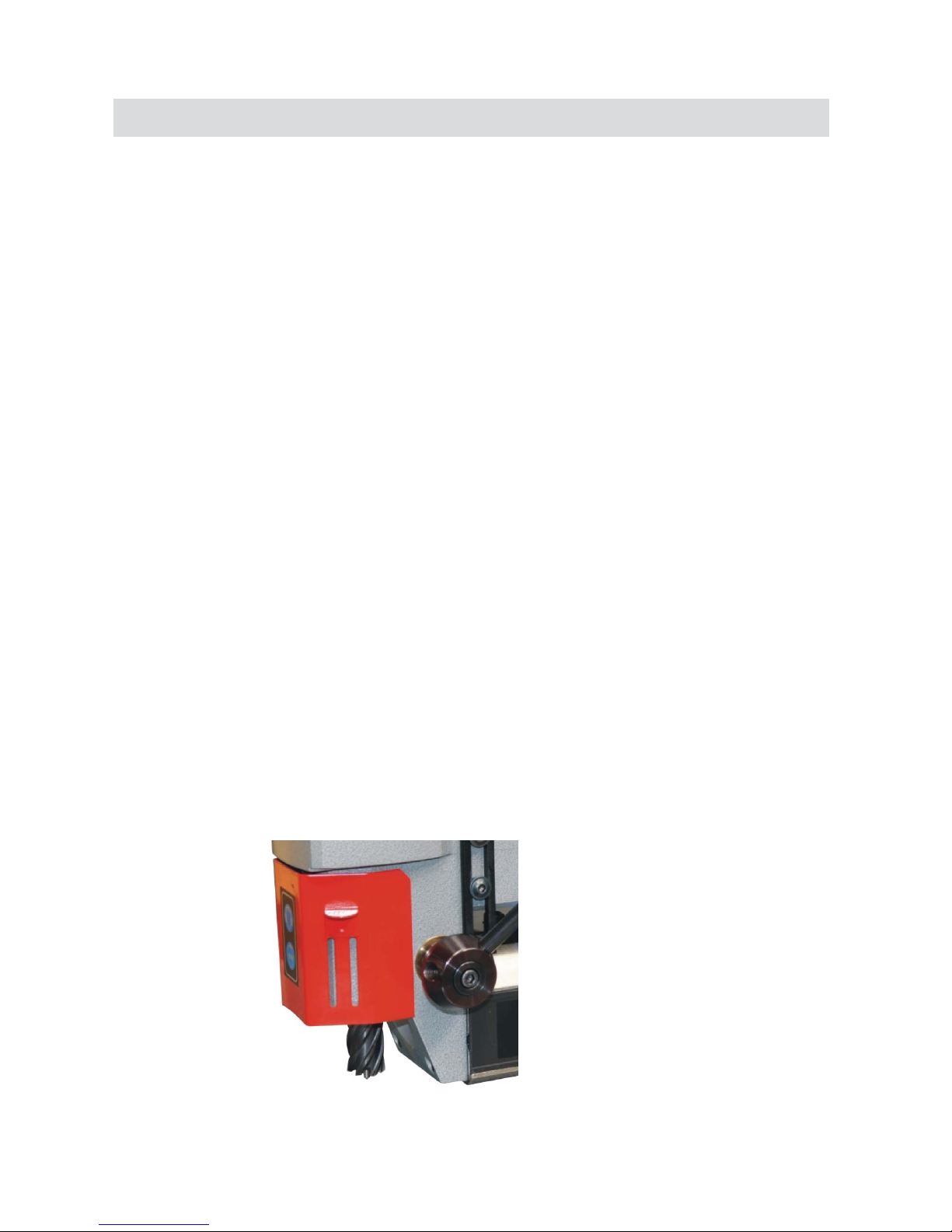
Fig. 1
Always use cutter guard supplied with machine to reduce the risk of injury. (refer fig. 1)
what you are doing. Use common sense. Do not operate tool when you are tired.
• Do not use when taking medications that may cause drowsiness.
17. Check Damaged Parts
• Before further use of the tool, any damaged parts should be repaired and performance verified prior to operation.
• Check alignment of moving parts, binding of parts, breakage of parts, mounting, and any other conditions
that may affect its operation. Any part that is damaged should be properly repaired or replaced
by an authorized service center.
• Do not use this tool if switches do not turn it on and off. Have defective switches replaced by authorized
service center.
4
IMPORTANT SAFETY INSTRUCTIONS
18. Use Cutter Guard
•
Page 5
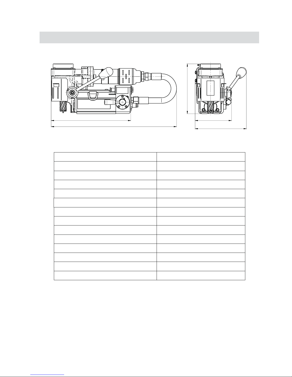
TECHNICAL DATA
5
Operating pressure 85 PSI
Air consumption
1400 l/min
800WattMotor Power
Arbor size 3/4” Weldon /19,05 mm/
Hole capacity with Holemaker cutter 35mm (1.38 in)
Maximum drilling depth 25mm (0.98 in)
Stroke 39mm (1.54 in)
Magnet force on 25mm Plate 6,500 N
500 rpmFree Speed
240 rpmLoad speed
Magnetic base 80x80x143 mm
Weight 14kg
Noise level above 70 dB
Working temperature range
-20C /+ 40C
183
133
188
460
292
The compressed-air motor used in the HMP35AD drill is certified ATEX II2G/D C
IIC T6;T4 and meets the requirements for use in areas with a risk of explosion.
Page 6

SPECIAL INSTRUCTIONS
1. Read and follow operator’s manual thoroughly.
2. DO NOT touch rotating cutter or parts.
3. Always stop machine completely and unplug from air supply before changing cutters, clearing swarf,
refilling lubrication or performing adjustments.
4. Never wear loose clothing or gloves when working near cutting area or machine arbor.
5. Always wear eye protection. Any tool can shatter.
6. Always use safety chain or strap provided with machine.
7. Always use proper tooling. Keep cutters securely fastened.
8. DO NOT use dull or broken cutters.
9. Beware of ejected slugs at end of cut. They become HOT during the cut.
10. Keep all safety features functioning and working properly.
11. Keep bottom of magnet burr free and clear of chips and debris.
12.
Use only authorized service centers for repairs.
Remove all contents from packaging and inspect to ensure no damage was incurred during shipping.
Your Holemaker package should include the following:
QTYDESCRIPTION
METAL CARRY CASE
HOLEMAKER HMP35AD MACHINE
1
1
SAFETY CHAIN WITH CLIP
1
OPERATORS MANUAL
1
COOLANT BOTTLE ASSEMBLY
1
FEED HANDLE
WHAT YOU SHOULD KNOW BEFORE YOU DRILL
1. Type of material to be drilled, Brinnell or Rockwell hardness, material thickness and position should all be
determined to ensure proper selection of cutting tools.
2. Remove any excessive mill scale or rust from surface to be drilled.
3. When drilling thin materials,
it is
recommend
ed that you
place a steel plate under the work piece and Holemaker
magnet area to increase magnetic holding force.
4. Material that has been flame cut may become heat treated and therefore difficult to drill. Avoid drilling near such
areas whenever possible.
5. Special cutter lubricant is available for using the Holemaker and annular cutters in the horizontal
position. Consult you distributor for more information.
The Holemaker HMP35AD is not designed for use on steel thinner than 3/8” or 10mm, as the magnet’s adhesive
power would be significantly reduced which can cause machines failure or individuals injury.
Never use the pneumatic hose running from the motor to the machines frame as a lifting handle.
6
1
HEX WRENCH 4
1
1
HEX WRENCH 4
Page 7
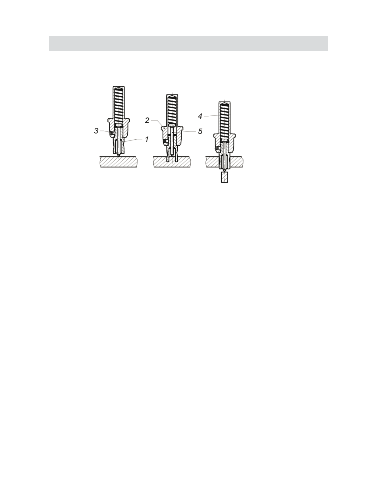
This drilling machine’s spindle has a 19mm Weldon Shank type and is specifically designed for use with Annular cutters.
Annular cutter (1) is located inside arbor body (2) and is fastened with grub screws (3). When fastening the cutter
in the arbour, ensure that the grub screws are firmly tightened to avoid them coming loose during operation. It is
important to position the cutter in relation to the arbour in such a way that fixing flats on the cutter shank are
positioned opposite to the grub screws (3). Both grub screws(3) should be used to fasten the cutter. The Pilot Pin (5)
is located inside the cutter to easily position the annular cutter over centre of a planned hole. During drilling as the cutter
goes into the material, the pilot pin moves back into the arbour body and pressurizes the discharge spring (4).That spring
ejects the slug which is a by-product of drilling the hole with a centre free cutter.
START UP AND OPERATION
Principle of Annular cutter’s work
CAUTION: READ THE WHOLE INSTRUCTIONS MANUAL
BEFORE ATTEMPTING TO START UP
7
Before you cut
Before positioning the machine on work piece always make sure that:
- work piece is made of ferrous material
- thickness of work piece is adequate for secure magnetic adhesion (mild
steel - 10mm is recommended)
- Ensure no part of magnet overhangs the steel workpiece
- surface of steel under the magnet is flat
- wipe, brush or sand down clean surface where you intended to place the
drilling machine, so that you remove rust, paint, dirt etc which would reduce adhesive
power of the electromagnetic base.
Install annular cutter in the machine before plugging it into air supply
Always make sure prior to use that the machine is secured from falling
down with a chain/strap.
Steel elements of this machine are coated with a layer of lubricant for the
period of storage and transport, and must be cleaned off prior to their usage.
Page 8
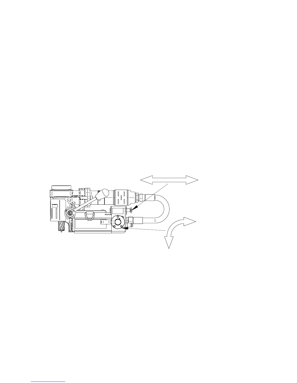
ON
MAGNET
OFF
OFF
ON
MOTOR
Fig. 4
8
Cutting
- Choose a suitable lubricating fluid and fill the coolant tank.
The cooling system is an integral part of the machine and should always be used.
Warning: The cooling system works gravitationally, therefore it can be used
only when in vertical position of the drilling machine. In other positions, a
cutting paste should be used
- Check workings of cooling system. Open the coolant tank’s tap and apply
pressure on the pilot by turning spokes counter clockwise. As the pilot starts to sink
into the cutter, cooling liquid should start to run down the groove in pilot pin. If there is
no liquid flowing down, check if the tap is fully opened. It may take a few seconds for
cooling liquid to fill the whole system.
Making a hole with an annular cutter should ideally be done in one pass. Do not peck drill.
WARNING
: When the annular cutter goes through the material the slug can be pushed out often with
considerable strength. Pay attention to avoid injury.
- After a hole is made the cutter should be retracted and both the motor
and the electromagnet should be switched OFF.
- When work with the machine is finished the machine should be
disconnected from the air supply, the machine should be cleaned up from swarf,
coolant etc. and the cutter should be removed and cleaned.
In order to start the machine:
- Make sure that the motor connection lever is in the OFF position.
turn the magnet switch to the ON position. turn the motor connection lever to the ON position.
- turning the motor connection lever to the OFF position will cause the motor to stop
running. The magnetic base will still be on.
- in order to change the drilling location, the magnet switch should be set to the OFF
position after the drive has been stopped.
Page 9

- Regularly grease the pinion and the teeth on the pinole sleeve.
- All component parts should be cleaned and maintained with a thin oil film.
- Use only clean, detergent-free oil with a density compliant with SAE 10 (90SSU)
or lower.
- When working with a pneumatic motor, it is necessary to use an air preparation
unit.
ATTENTION: The pneumatic motor’s guarantee is invalid when damages arise
from pollution in the air feed or lack of lubrication.
- Lubrication of the pneumatic motor.
- Direct servicing is not necessary when drill usage is normal.
- It is necessary to use an air preparation unit in the air feed system.
- Inspections and servicing of the air preparation unit should be carried out
as needed depending on the air pollution level. Clean the filter, dry out
the dehydrator, and maintain an oil level with drips every 2-5 seconds.
- Oil used in the air preparation unit must have an ignition temperature
higher than 260°C.
- Any type of mechanical repair of the drill should be done at a service
workshop recommended by the vendor. When repairing use only original parts.
ATTENTION: The HMP35AD drill is designed to be powered by air with working
pressure 4 to 6 bar /60 to 90 PSI/. Maintenance of the machine's technical
parameters and its general state are strictly dependent on the cleanness and
preparation of the air and proper servicing.
MAINTENANCE AND SERVICE
9
Page 10

BASIC TROUBLESHOOTING
1. Magnetic base not holding securely
• Material is too thin.
• Surface of material being drilled must be free of chips, debris, rust and mill scale.
• Does size of cutter exceed machine’s rated capacity?
• Check magnet face for unevenness, nicks and burrs.
2. Drill motor running, arbor and spindle not turning
• Possible sheared drive train component.
3. Motor slows when drilling
• Excessive downfeed pressure during drilling cycle will cause motor to slow
• Does cutting tool need to be resharpened?
4. Coolant system not working
• Dirt or debris in coolant tank.
• Consistency of coolant mixture too thick.
• Is correct pilot pin being used?
• Vent hole in coolant tank lid blocked.
5. Slugs not ejecting from cutter
• Lack of coolant causing slugs to expand in cutter bore.
• Is correct pilot pin being used?
• Possible broken internal arbor parts.
6. Breaking cutters
• How is coolant being applied? Coolant must be supplied to interior of cutter.
• Excessive feed pressure being applied when cutter initially contacts work surface.
• Confirm material hardness.
• Drilling stacked materials with incorrect cutter.
• Dull cutters; dull or chipped cutting edges require excessive feed pressure, resulting in breakage.
••Movement of machine on material - See “1. Magnetic base not holding securely”
Inconsistent hardness in material can cause cutter breakage
7. Oversized or rough holes
• Insufficient coolant.
• Excessive feed pressure.
• Dull cutter.
10
Page 11

11
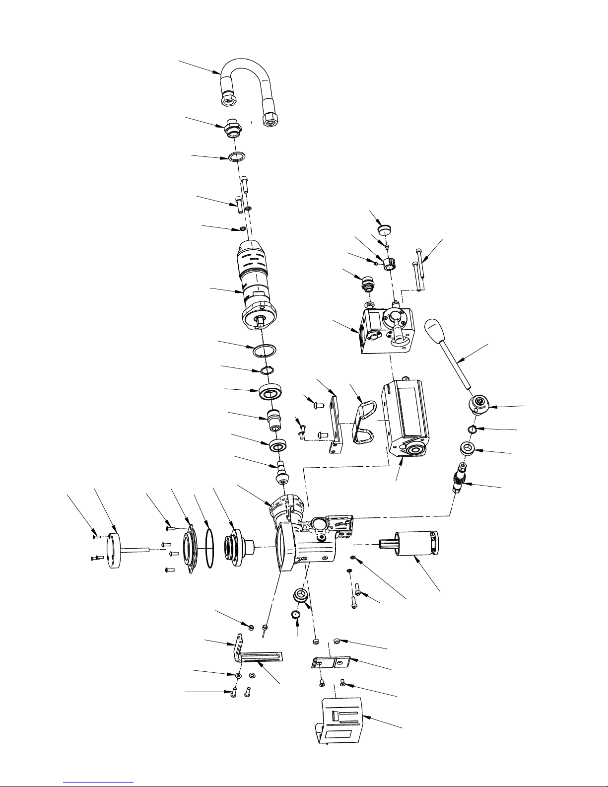
ITEM PART NUMBER DESCRIPTION QTY
1 1MAIN BODY ASSEMBLY
VALVE ASSEMBLY
QUILL ASSEMBLY
BEVEL GEAR T=39 ASSEMBLY,
GEAR BOX COVER ASSEMBLY,
BEARING NUT HOLDER,
SLEEVE
PINION
DRIVER
MAIN BODY BRACKET
MOTOR HOSE ASSY
GEARSHFT T=11,
HEAD ASSEMBLY,
SPOKE HANDLE INCLUDING 35406 KNOB
D-RING STRAP
STRAIGHT COUPLING 1/2" - 3/8"
STRAIGHT COUPLING 3/4" - 3/8"
HOLDER SLEEVE
HOLDER
TURN ON/OFF GEAR
GEAR PLUG
GUARD'S SLIDE
GUARD ASSEMBLY
SOCKET BUTTON HEAD CAP SCREW M5
SCREW M8x16
SOCKET BUTTON HEAD CAP SCREW M6
SCR, M4 x 16 FHSCS
SCR, M6 x 12 FHSCS
SPRING WASHER 6,1
SPRING WASHER 8.2
ROUND WASHER 6,4
HEX. SOCKET BOLT M4x6
HEX. SOCKET BOLT M6x20
HEX. SOCKET BOLT M6x65
HEX SOCKET BOLT-M8X30
EXTERNALE RETAINING RING 16z
EXTERNALE RETAINING RING 25z
INTERNAL RETAINING RING-47W
SEAL RING 80x1,3,
BEARING BALL 6003
BEARING, BALL 6005 ZZ
AIR MOTOR
SEAL, 3/4"
SWITCH CONNECTOR
HEX SET SCREW-M6 x 6
GUARD SLEEVE
LABELS, SET
MAGNET BASE
01
02
03
04
05
06
07
08
09
10
11
12
13
14
15
16
17
18
19
20
21
22
23
25
26
27
28
29
30
31
32
33
34
35
36
37
38
39
40
41
42
43
44
45
46
47
48
49
SPMP35
SPMP35
SPMP35
SPMP35
SPMP35
SPMP35
SPMP35
SPMP35
SPMP35
SPMP35
SPMP35
SPMP35
SPMP35
SPMP35
SPMP35
SPMP35
SPMP35
SPMP35
SPMP35
SPMP35
SPMP35
SPMP35
SPMP35
SPMP35
SPMP35
SPMP35
SPMP35
SPMP35
SPMP35
SPMP35
SPMP35
SPMP35
SPMP35
SPMP35
SPMP35
SPMP35
SPMP35
SPMP35
SPMP35
SPMP35
SPMP35
SPMP35
SPMP35
SPMP35
SPMP35
SPMP35
SPMP35
SPMP35
2 1
3 1
4 1
5 1
6 1
7 2
8 1
9 1
10 1
11 1
12 1
13 1
14
1
15 1
16 1
17 1
18 2
19 1
20 1
21 1
22 1
23 1
25
4
26 2
27 2
28 3
29 2
30 2
31 2
32 2
33 1
34 2
35 2
36 2
37 2
38 1
39 1
40 1
41 1
42 1
43 1
44 1
45 1
46 1
47 2
48 1
49 1
Page 12
12
1
2
3
4
5
6
7
7
8
9
10
11
12
13
14
15
16
17
18
19
20
21
22
23
25
26
27
28
48
30
31
32
33
34
35
36
37
37
38
39
40
41
42
43
44
45
46
47
29
49
Page 13
13
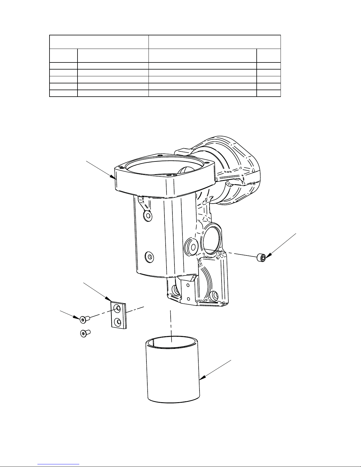
ITEM PART NUMBER DESCRIPTION QTY
1.1 1MAIN BODY
BUSHING PERMAGLIDE
HEX. INSERT SCREW M8x6
MAIN BODY PLATE
SCR, M4 x 10 FHSCS
SPMP350101
SPMP350102
SPMP350103
SPMP350104
SPMP350105
1.2
1.3 1
1.4 1
1.5 2
Part Number:SPMP3501
MAIN BODY ASSEMBLY
1
3
4
5
2
Page 14

14
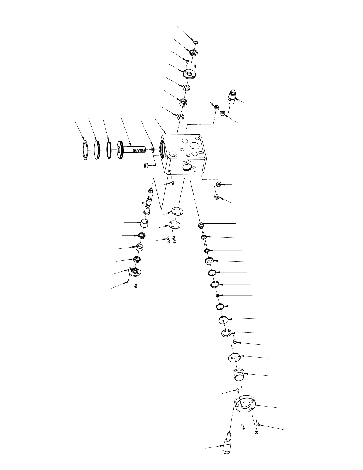
ITEM PART NUMBER DESCRIPTION QTY
2.1 0201
0202
0203
0204
0205
0206
0207
0208
0209
0210
0211
0212
0213
0214
0215
0216
0217
0218
0219
0220
0221
0222
0223
0224
0225
0226
0227
0228
0229
0230
0231
0232
0233
0234
0235
0236
0237
SPMP35
SPMP35
SPMP35
SPMP35
SPMP35
SPMP35
SPMP35
SPMP35
SPMP35
SPMP35
SPMP35
SPMP35
SPMP35
SPMP35
SPMP35
SPMP35
SPMP35
SPMP35
SPMP35
SPMP35
SPMP35
SPMP35
SPMP35
SPMP35
SPMP35
SPMP35
SPMP35
SPMP35
SPMP35
SPMP35
SPMP35
SPMP35
SPMP35
SPMP35
SPMP35
SPMP35
SPMP35
VALVE HOUSING
PISTON ASSY
PISTON PLUG
STOP PLUG
LOCKING RING
SPRING
BALL LOCK GN 614-8-NI
EXTERNAL RING
HANDLE HOLDER
WASHER
HANDLE SHAFT
HANDLE ASSY
SEAL COVER
COVER
DIVIDING SHAFT
SLEEVE I
SLEEVE CENTER
SLEEVE II
COVER I
COVER II
SHAFT RING
SCR, M3 x 8 FHSCS
SCR, M4 x 16 FHSCS
HEX. INSERT SCREW M5x8
HEX. INSERT SCREW M12x8
PIN 4x10
EXTERNAL RETAINING RING 8z
RETAINING RING INTERNAL 21w
RETAINING RING INTERNAL 24w
INTERNAL RETAINING RING-47W
O-RING 9x2
O-RING 15,3x2,4
O-RING 18x2
O-RING 42x2
SEAL, 4x8,2x4
SEAL U2 012x18.4
MALE PLUG, G3/8" 10mm
1
2.2 1
2.3 1
2.4 1
2.5 1
2.6 1
2.7 1
2.8 1
2.9 1
2.10 1
2.11 1
2.12 1
2.13 1
2.14 1
2.15 1
2.16 1
2.17 2
2.18 1
2.19 1
2.20 1
2.21 1
2.22 8
2.23 3
2.24 1
2.25 4
2.26 1
2.27
1
2.28 1
2.29 1
2.30 1
2.31 1
2.32 1
2.33 2
2.34 1
2.35 1
2.36 4
2.37 1
Part Number:SPMP3502
VALVE ASSEMBLY
Page 15
15
1
2
3
4
7
5
6
8
9
10
11
12
13
14
15
16
17
18
19
20
21
22
22
22
23
24
25
25
25
25
26
27
28
29
30
31
32
33
33
34
35
36
36
36
36
37
Page 16
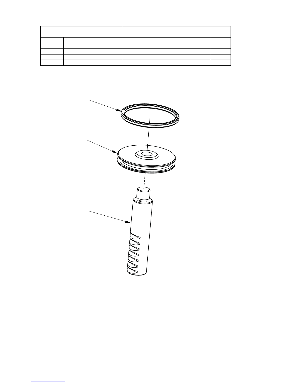
16
ITEM PART NUMBER DESCRIPTION QTY
2.2.1
SPMP35020201
SPMP35020202
SPMP35020203
PISTON
PISTON GEAR RACK
O-RING 39,2x3
1
2.2.2 1
2.2.3 1
Part Number:SPMP350202
PISTON ASSY
1
2
3
Page 17
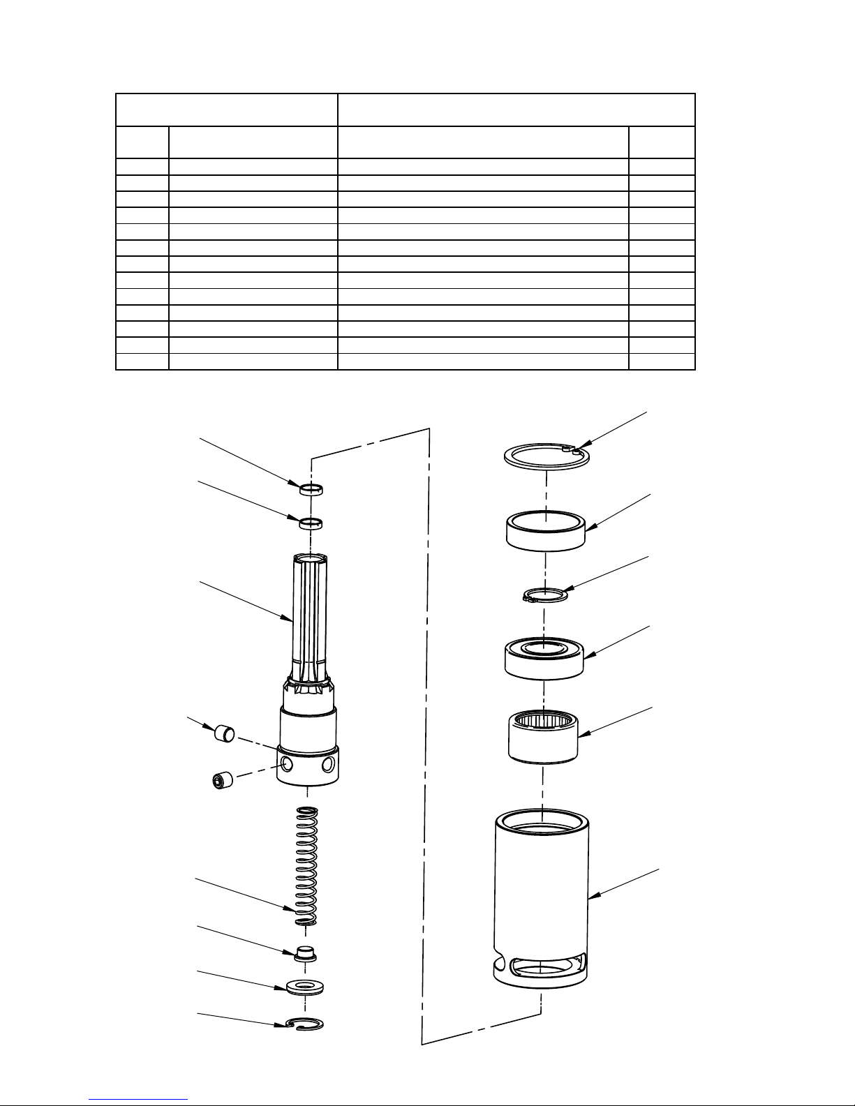
17
YTQNOITPIRCSEDREBMUN TRAPMETI
3.1
3.2
3.3
3.4
3.5
3.6
3.7
3.8
3.9
3.10
3.11
3.12
3.13
SPMP3503
SPMP3503
SPMP3503
SPMP3503
SPMP3503
SPMP3503
SPMP3503
SPMP3503
SPMP3503
SPMP3503
SPMP3503
SPMP3503
SPMP3503
01
02
03
04
05
06
07
08
09
10
11
12
13
QUILL CARRIER
SPINDLE
DISTANCE SLEEVE
SPRING
SEAL
PLUNGER
NEEDLE BEARING RHNA303720
BEARING BALL 6004 2RS
INTERNAL RETAINING RING 19W
EXTERNAL RETAINING RING- 20Z
INTERNAL RETAINING RING - 42W
HEX SET SCREW M8x10
SEAL RING TRK000080
1
1
1
1
1
1
1
1
1
1
1
2
2
Part Number:SPMP3503
QUILL ASSEMBLY
01
02
03
04
05
06
07
08
09
10
11
12
13
13
Page 18
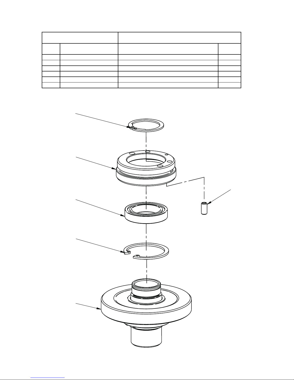
18
YTQNOITPIRCSEDREBMUN TRAPME
4.1
4.2
4.3
4.4
4.5
4.6
SPMP350401
SPMP350402
SPMP350403
SPMP350404
SPMP350405
SPMP350406
BEVEL GEAR T=39 ASSY / INCL. SLEEVE
BEARING NUT
BEARING BALL 61805 2RS
EXTERNAL RETAINING RING 25Z TYPE A
INTERNAL RETAINING RING 37W
HEX SET SCREW M5x10
1
1
1
1
1
1
TI
Part Number:SPMP3504
BEVEL GEAR T=39 ASSEMBLY
01
02
05
04
06
03
Page 19
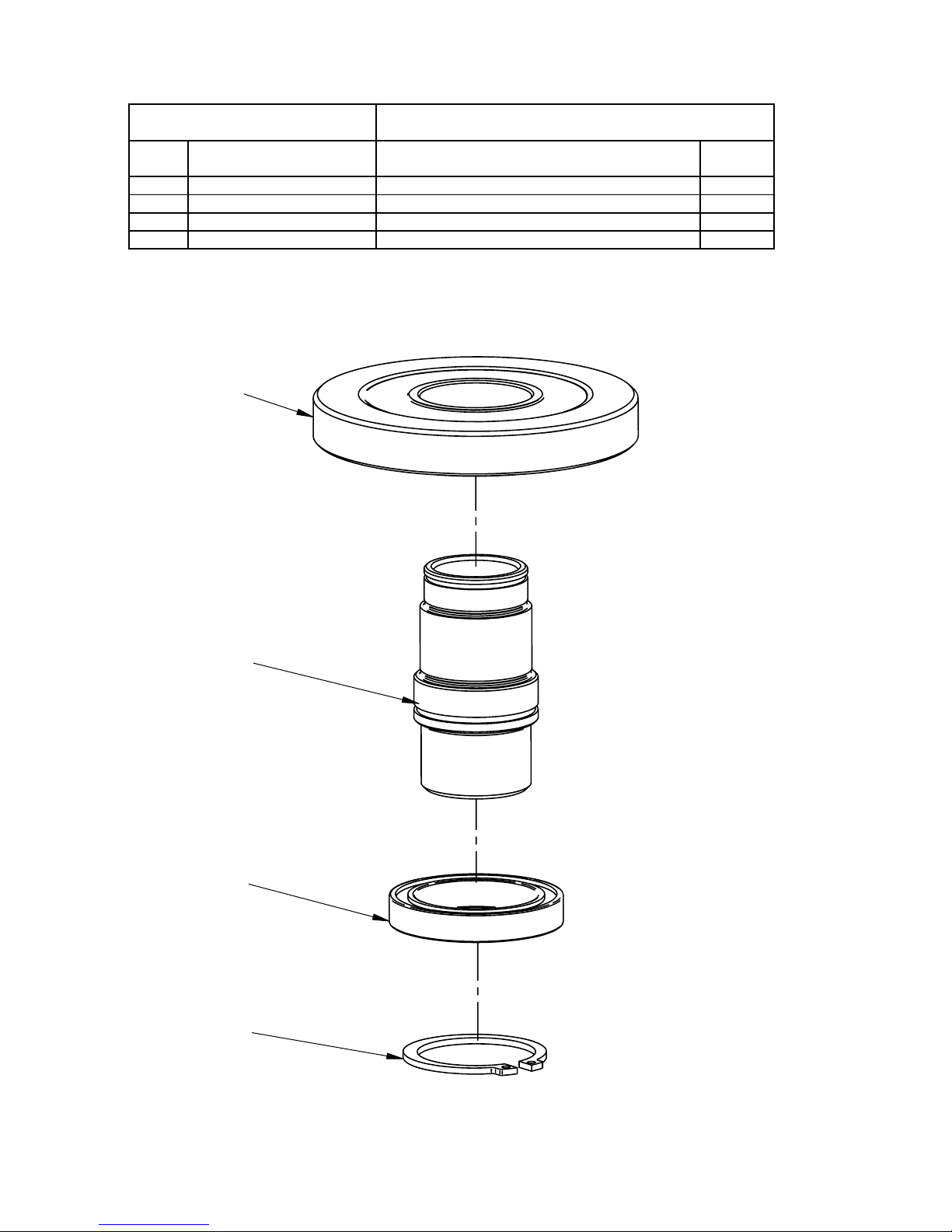
19
YTQNOITPIRCSEDREBMUN TRAPMETI
14.1.1
4.1.2
4.1.3
4.1.4
SPMP35040101
SPMP35040102
SPMP35040103
SPMP35040104
SLEEVE
BEVEL GEAR T=39
BEARING BALL 6806 LLU
EXTERNAL RETAINING RING 30z
1
1
1
Part Number:SPMP350401
BEVEL GEAR T=39 ASSY / INCL. SLEEVE
01
02
03
04
Page 20
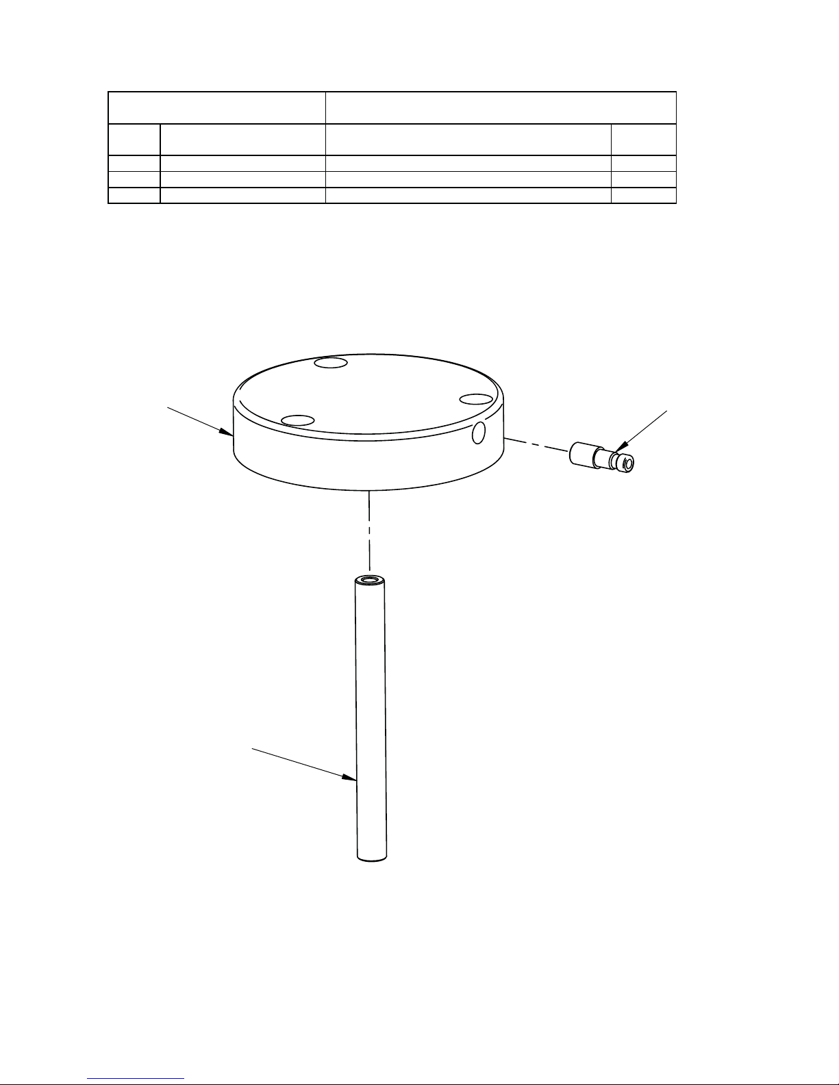
20
YTQNOITPIRCSEDREBMUN TRAPMETI
1REVOC XOB RAEG1.5 SPMP350501
SPMP350502
SPMP350503
1REPMUJ2.5
191-H-2TMA ruf leppinssulhcsnA3.5
Part Number:SPMP3505
GEAR BOX COVER ASSEMBLY
01
02
03
 Loading...