

Page 1
39K
DIGITAL MULTIMETER
OPERATOR’S MANUAL
1. Overview
The multimeter is characterized at slim size, portable, stable performance and
anti-dropping capacity. Using 4000 counts digit LCD monitor with character
25mm high, they offer clear readings. With overall circuitry design centering on
large-scale IC A/D converters in conjunction and over-load protection circuit, the
meters give excellent performance and exquisite making as a handy utility
instrument.
The meters can be used to measure DC & AC voltage, DC & AC current,
resistance, capacitor, frequency, duty cycle, Non Contact AC Voltage (NCV)
detection, positive diode voltage fall and audible continuity.
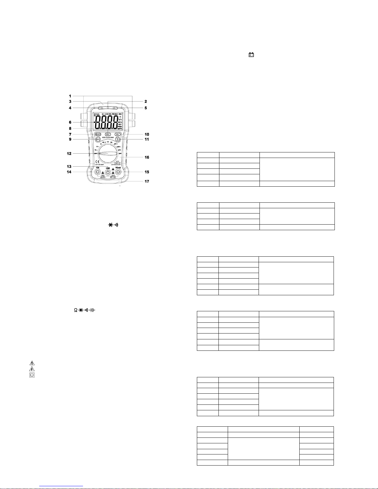
2. Panel Layout
1. Test lead fixture: Fix the test lead.
2. CDS sensor: The CDS sensor can reaction to the ambient brightness range,
then automatically control the LCD backlight to lighten or go out.
3. NCV detection area: Non Contact AC Voltage (NCV) detection area.
4. NCV red light: Non Contact AC Voltage (NCV) detection red light.
5. NCV green light: Non Contact AC Voltage (NCV) detection green light.
6. LCD display: 4000 counts digit, full function symbol display.
7. SELECT key: This key work on the " " range, press the key to choose
diode or continuity test, on the current range, change to DC or AC; If press and
hold SELECT key to power on, “Auto Power Off ” function will be disabled.
8. NCV Key: Press and hold the “NCV” key, the meter enters Non Contact AC
Voltage (NCV) detection, the NCV green LED light will light up, free it to exit.
9. HOLD key: Press the “HOLD” key to lock display value, and the “DH” sign will
appear on the display, press it again to exit.
10. REL Key: Press the “REL” key, the meter enters relative measuring mode,
“REL” is displayed on the LCD and the present reading becomes the reference
value and displayed on the display. Relative measurement REL△=measurement
value-Reference value. Press it again to exit.
11. Hz/% Key: On “ACV/ACA” or “Hz” range, press the “Hz/%” key, you can
choose the Frequency or Duty Cycle measurement.
12. Rotary Switch: Use this switch to select functions and ranges.
13. COM: COM Input Jack
14. 10A: 10A Input Jack
15. VΩmA: V/μAmA/Hz/ Input Jack
16. Crust of meter
17.Protective casing
3. Safety Information
3-1 The meter is designed according to IEC-1010 concerning electronic
measuring instruments with an over-voltage category 600V (CATⅢ) and
pollution 2.
3-2 Follow all safety and operating instructions to ensure that the meter is used
safely and is kept in good operating condition.
3-3 safety symbols:
Important safety information, refer to the operating manual.
Dangerous voltage may be presence.
Double insulation (protection Class II)
4. Special Cautions for Operation
4-1 The meters can be safe only according to standard procedures when used in
conjunctions with the supplied test leads. To replace damaged test leads with
only the same model or same electric specifications.
4-2 To avid risk of electric shock, do not use the meters before the cover is in
place.
4-3 The range switch should be right position for the testing.
4-4 To avoid electric shock and damaging the instruments, the input signals are
forbidden to exceed the specified limits.
4-5 When measuring TV set or switched power, attention should be paid to the
possible pulses that may bring destruction to the circuit.
4-6 Range switch position is forbidden to be changed at random during
measurement.
4-7 Take caution against shock in the course of measuring voltage higher than
DC 60V & AC 30V.
4-8 Protection fuse should be replaced only with same type and same
specification.
4-9 After operation is finished, set function switch at OFF to save battery power.
4-10 If the meter is without usage for long time, take out battery to avoid damage
by battery leakage.
5. GENERAL SPECIFICATIONS
5-1 Max Voltage between input terminal and Earth Ground: CAT Ⅲ 600V
5-2 Over-range Indication: display “OL” for the significant digit.
5-3 Automatic display of negative polarity “-” .
5-4 Low Battery Indication: “ ” displayed.
5-5 Max LCD display: 4000 counts digit.
5-6 Auto range control
5-7 Auto Power Off: When measurement exceeds 15 minutes without switching
mode and pressing key, the meter will switch to standby mode. Press any
key to exit standby mode. When restart the system, press and hold SELECT
key to disable auto power off.
5-8 Auto LCD backlight
5-9 Fuse protection: 500mA/500V Fast Fuse, 10A/500V Fast Fuse
5-10 Power supply: 1.5V×2 “AA” R6P battery
5-11 Operating Temp.: 0℃ to 40℃ (relative humidity <85%)
5-12 Storage Temp.: -10 ℃ to 50℃ (relative humidity <85%)
5-13 Guaranteed precision Temp.: 23±5℃ (relative humidity <70%)
5-14 Dimension: 150x100x36mm
5-15 Weight: approx. 250g (including battery)
6. Testing Specifications
Accuracy is specified for a period of year after calibration and at 18 ℃ to 28 ℃
(64℉ to 82℉) with
relative humidity to 70%.
6-1 DC Voltage
Range
Resolution
Accuracy
400mV
0.1mV
±(0.5% of rdg + 2 digits)
4V
1mV
40V
10mV
400V
100mV
600V
1V
±(0.8% of rdg + 2 digits)
-- Impedance: 10MΩ, More than 100MΩ on 400mV range
-- Overload protection: 600V DC or AC rms
6-2 AC Voltage
Range
Resolution
Accuracy
4V
1mV
±(0.8% of rdg + 3 digits)
40V
10mV
400V
100mV
600V
1V
±(1.2% of rdg + 3 digits)
-- Impedance: 10MΩ
-- Overload protection: 600V DC or AC rms
-- Frequency Range: 40 to 400Hz
-- Response: average, calibrated in rms of sine wave
6-3 DC Current
Range
Resolution
Accuracy
400μA
0.1μA
±(1.2% of rdg + 2 digits)
4000μA
1μA
40mA
10μA
400mA
100μA
4A
1mA
±(2.0% of rdg + 3 digits)
10A
10mA
-- Overload protection: 500mA/500V Fast Fuse
10A/500V Fast Fuse, 10A up to 10 seconds
6-4 AC Current
Range
Resolution
Accuracy
400μA
0.1μA
±(1.5% of rdg + 3 digits)
4000μA
1μA
40mA
10μA
400mA
100μA
4A
1mA
±(2.5% of rdg + 5 digits)
10A
10mA
-- Overload protection: 500mA/500V Fast Fuse
10A/500V Fast Fuse, 10A up to 10 seconds
-- Frequency Range: 40 to 400Hz
-- Response: average, calibrated in rms of sine wave
6-5 Resistance
Range
Resolution
Accuracy
400Ω
0.1Ω
±(1.0% of rdg + 3 digits)
4kΩ
1Ω
±(1.0% of rdg + 2 digits)
40kΩ
10Ω
400kΩ
100Ω
4MΩ
1kΩ
40MΩ
10kΩ
±(1.5% of rdg + 3 digits)
-- Overload protection: 500V DC or AC rms
6-6 Capacitance
Range
Accuracy
Resolution
5.12nF
±(3.0% of rdg + 10 digits)
1pF
51.2nF
±(2.5% of rdg + 5 digits)
10pF
512nF
100pF
5.12µF
1nF
51.2µF
10nF
200µF
±(5.0% of rdg + 10 digits)
100nF
-- Overload protection: 500V DC or AC rms
Page 2
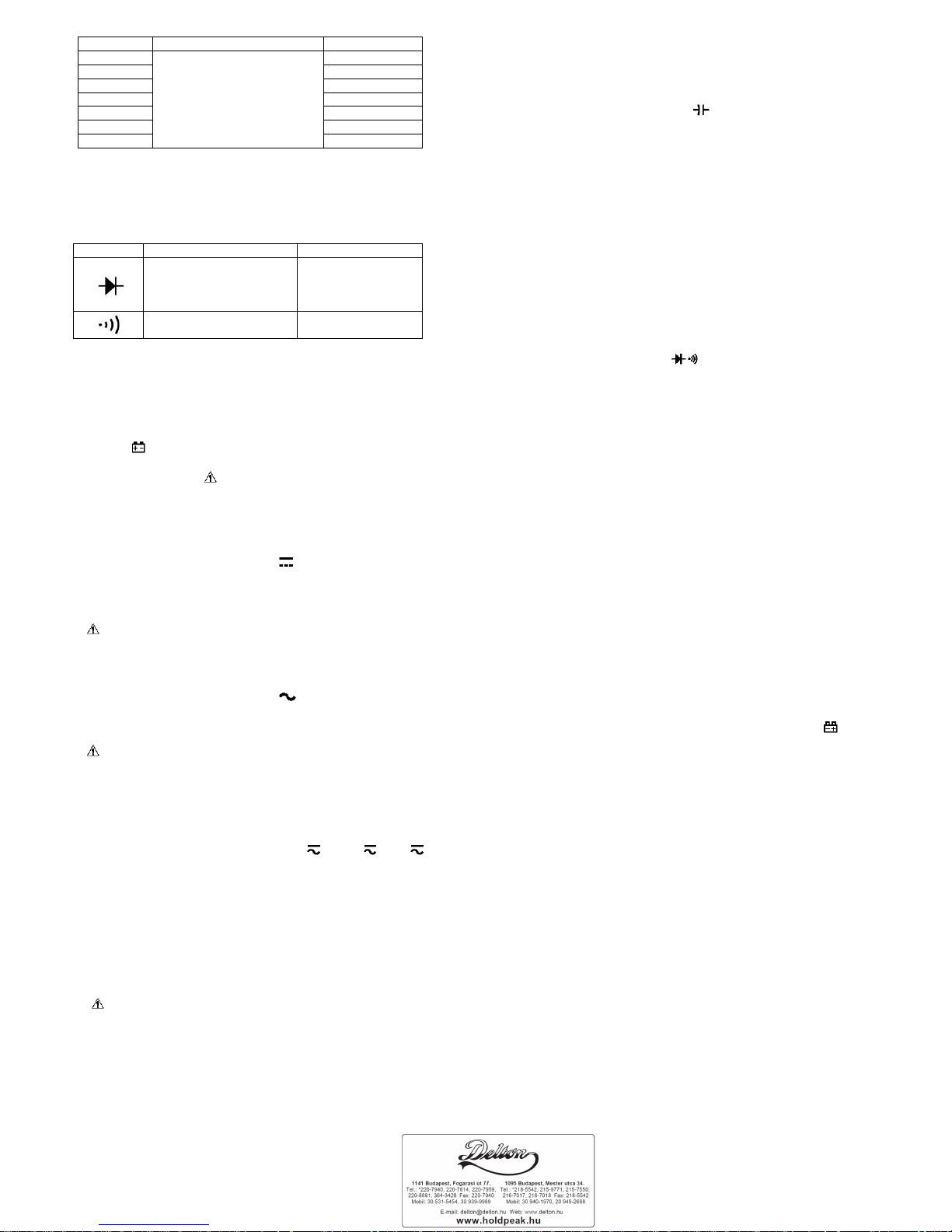
6-7 Frequency
Range Accuracy Resolution
5.12Hz
± (0.1% of rdg + 5 digits)
0.001Hz
51.2Hz 0.01Hz
512Hz 0.1Hz
5.12kHz 1Hz
51.2kHz 10Hz
512kHz 100Hz
5.12MHz 1kHz
-- Sensitivity: sine wave 0.6V rms (5.12MHz: 1.5V rms)
-- Overload protection: 500V DC or AC rms
6-8 Duty cycle
0.1%~
99.9%: ± ( 2.0% of rdg + 2 digits ), Frequency lower than 10kHz
-- Sensitivity: sine wave 0.6V rms
-- Overload protection: 500V DC or AC rms
6-9 Diode and Audible continuity test
Range Description Test Condition
Display read approximately
forward voltage of diode
Forward DC current
approx. 0.4mA
Reversed DC voltage
approx. 1.5V
Built-in buzzer sounds if
resistance is less than 100Ω
Open circuit voltage
approx. 0.5V
Overload protection: 500V DC or AC rms
6-10 Non Contact AC Voltage (NCV) detection
Test voltage range: 90V~1000V AC rms
The NCV red light and green light will light up alternately together with sound.
7. OPERATING INSTRUCTIONS
7-1 Attention before operation
7-1-1 Check battery. When the battery voltage drop below proper operation
range, the “ ” symbol will appear on the LCD display and the battery need to
changed.
7-1-2 Pay attention to the “ ” besides the input jack which shows that the input
voltage or current should be within the specified value.
7-1-3 The range switch should be positioned to desired range for measurement
before operation.
7-2 Measuring DC Voltage
7-2-1 Connect the black test lead to COM jack and the red to VΩmA jack.
7-2-2 Set the rotary switch at the desired V range position.
7-2-3 Connect test leads across the source or load under measurement.
7-2-4 You can get reading from LCD. The polarity of the red lead connection will
be indicated along with the voltage value.
NOTE:
1.“ ” means you can’t input the voltage more than 600V, it’s possible to show
higher voltage, but it may destroy the inner circuit or pose a shock.
2. Be cautious against shock when measuring high Voltage.
7-3 Measuring AC Voltage
7-3-1 Connect the black test lead to COM jack and the red to VΩmA jack.
7-3-2 Set the rotary switch at the desired V range position.
7-3-3 Connect test leads across the source or load under measurement.
7-3-4 You can get reading from LCD.
NOTE:
1.“ ” means you can’t input the voltage more than 600V, it’s possible to show
higher voltage, but it may destroy the inner circuit or pose a shock.
2. Be cautious against shock when measuring high Voltage.
7-4 Measuring DC & AC Current
7-4-1 Connect the black test lead to COM jack and the red to the VΩmA jack for
a maximum 400mA current , for a maximum 6A or 10A current, move the red
lead to the 10A jack.
7-4-2 Set the rotary switch at the desired “uA ” & “mA ” & “A ” range
position, it shows symbol for testing DC current, if you want to test AC current,
push “SELECT” button switch.
7-4-3 Connect test leads in series with the load under measurement.
7-4-4 You can get reading from LCD. The polarity of the red lead connection will
be indicated along with the DC current value.
NOTE:
1. When the value scale to be measured is unknown beforehand, set the range
selector at the highest position.
2. When only “OL” is displayed, it indicates over-range situation and the higher
range has to be selected.
3. “
” means the socket mA’s maximum current is 500mA and 10A’s maximum
current is 10A, over 500mA or 10A current can be protected by the fast
fuse.
4. On the 10A range, the measuring time should be less than 10 seconds to
prevent precision from affecting by circuit heating.
7-5 Measuring Resistance
7-5-1 Connect the black test lead to COM jack and the red to VΩmA jack.
7-5-2 Set the rotary switch at the desired “Ω” range position.
7-5-3 Connect test leads across the resistance under measurement.
7-5-4 You can get reading from LCD.
NOTE: Max. input overload: 500V rms<10sec
1.
For measuring resistance above 1MΩ, the mete may take a few
seconds to get stable reading.
2. When the input is not connected, i.e. at open circuit, the figure ‘OL’ will be
displayed for the over-range condition.
3. When checking in-circuit resistance, be sure the circuit under test has all
power removed and that all capacitors have been discharged fully.
7-6 Measuring Capacitance
7-6-1 Connect the black test lead to COM jack and the red to VΩmA jack.
7-6-2 Set the rotary switch at the desired “ ” range position.
7-6-3 Connect test leads across the capacitance under measurement.
7-6-4 You can get reading from LCD.
NOTE: Max. input overload: 500V rms<
10sec
1. Capacitors should be discharged before being tested.
2. When testing large capacitance, it will take longer time before the final
indication ( For 200uF range, it will take about 15 seconds ).
3. When testing small capacitance (≤1uF), to assure the measurement
accuracy, first press "REL", then go on measuring.
7-7 Measuring Frequency & Duty cycle
7-7-1 Connect the black test lead to COM jack and the red to VΩmA jack.
7-7-2 Set the rotary switch at the desired “Hz” range position.
7-7-3 Push “Hz/%” key to choose Frequency or Duty cycle test.
7-7-4 Connect the probe across the source or load under measurement.
7-7-5 You can get reading from LCD.
7-8 Diode & Audible continuity Testing
7-8-1 Connect the black test lead to COM jack and the red to VΩmA jack.
7-8-2 Set the rotary switch at the “ ” range position, push “SELECT” to
choose Diode or Audible continuity measurement.
7-8-3 On diode range, connect the test leads across the diode under
measurement, display shows the approx. forward voltage of this diode.
7-8-4 On Audible continuity range, connect the test leads to two point of circuit,
if the resistance is lower than approx. 100Ω, the buzzer sounds.
NOTE: Make sure the power is cut off and all capacitors need to be discharged
under this measurement.
7-9 Non Contact AC Voltage detection
7-9-1 Power on the meter, on any range, press and hold the “NCV” key, the
meter enters Non Contact AC Voltage (NCV) detection, the NCV green
LED light will light up.
7-9-2 Hold the Meter so that the mater’s top is vertically and horizontally
centered and contacting the conductor, when the live voltage ≥ 90V AC
rms, the NCV red LED light and green LED light will light up alternately
together with sound.
NOTE:
1. Even without LED indication, the voltage may still exist. Do not rely on
non-contact voltage detector to determine the presence of voltage wire.
Detection operation may be subject to socket design, insulation thickness and
different type and other factors.
2. When the meter input terminals presence voltage, due to the influence of
presence voltage, voltage sensing indicator may also be bright.
3. Keep the meter away from electrical noise sources during the tests, i.e.,
florescent lights, dimmable lights, motors, etc.. These sources can trigger
Non-Contact AC Voltage detection function and invalidate the test.
8. Battery replacement
8-1 When the battery voltage drop below proper operation range the "
"
symbol will appear on the LCD display and the battery need to changed.
8-2 Before changing the battery, set the selector switch to “OFF” position and
remove the test leads from the terminals. Open the cover of the battery
cabinet by a screwdriver.
8-3 Replace the old battery with the same type battery (AA R6P 1.5V×2).
8-4 Close the cover of the battery cabinet and fasten the screw.
9. Fuse replacement
9-1 This meter is provided with a 500mA/50
0V fast fuse to protect the current
measuring circuits which measure up to 400mA, with a 10A/500V fuse to
protect the 10A range.
9-2 Ensure the meter is not connected to any external circuit, set the selector
switch to “OFF” position and remove the test leads from the terminals. Open
the cover of the battery cabinet by a screwdriver.
9-3 Replace the old fuse with the same type and rating: 6×30mm 500mA/500V
fast fuse or 6×30mm 10A/500V fast fuse.
9-4 Close the cover of the battery cabinet and fasten the screw.
10. Maintenance
10-1 You must replace the test leads if the lead is exposed, and should adopt the
leads with the same specifications as origin.
10-2 Use only moist fabric or small amount of detergent but not chemical
solution for cleaning.
10-3 Do not use the meter before the back cover is properly closed and screw
secured. Upon any abnormality, stop operation immediately and send the
meter for maintenance.
10-4 Please take out the battery when not using for a long time.
11. Accessories
[1] Test Leads: electric rating 1000V 10A
[2] Operator’s Manual
 Loading...