

Holding Cabinets HC-900 Service Manual

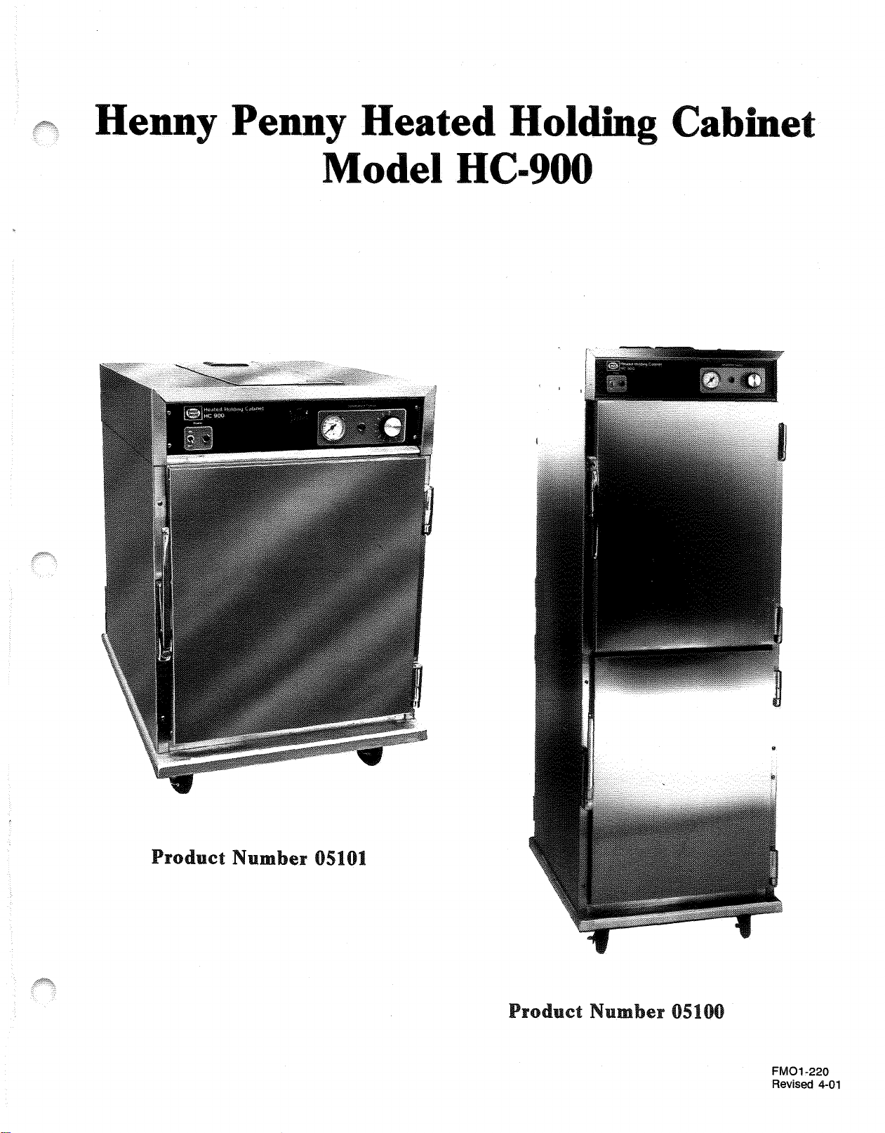
Henny Penny
Heated Holding Cabinet
Model HC 900
SERVICE MANUAL

enn
FMO1-220
Revised 4-01

Henny Penny
LIMITED WARRANTY FOR HENNY PENNY APPLIANCES
Subject to the following conditions, Henny Penny Corporation makes the following limited warranties to the
original purchaser only for Henny Penny appliances and replacement parts:
NEW EQUIPMENT:
defective in material or workmanship within two (2) years from date of original installation, will be
repaired or replaced without charge F.O.B. factory, Eaton, Ohio, or F.O.B. authorized distributor. To
validate this warranty, the registration card for the appliance must be mailed to Henny Penny within ten
(10) days after installation.
REPLACEMENT PARTS:
be defective in material or workmanship within ninety (90) days from date of original installation will be
repaired or replaced without charge F.O.B. factory, Eaton, Ohio, or F.O.B. authorized distributor.
The warranty for new equipment and replacement parts covers only the repair or replacement of the defective
part and does not include any labor charges for the removal and installation of any parts, travel or other expenses
incidental to the repair or replacement of a part.
EXTENDED FRYPOT WARRANTY:
workmanship issues for a period of up to seven (7) years from date of manufacture. This warranty shall not cover
any frypot that fails due to any misuse or abuse, such as heating of the frypot without shortening.
0 TO 3 YEARS:
issues will be replaced at no charge for parts, labor, or freight. Henny Penny will either install a
new frypot at no cost or provide a new or reconditioned replacement fryer at no cost.
3 TO 7 YEARS:
issues will be replaced at no charge for the frypot only. Any freight charges and labor costs to
install the new frypot as well as the cost of any other parts replaced, such as insulation, thermal
sensors, high limits, fittings, and hardware, will be the responsibility of the owner.
Any part of a new appliance, except lamps and fuses, which proves to be
Any appliance replacement part, except lamps and fuses, which proves to
Henny Penny will replace any frypot that fails due to manufacturing or
During this time, any frypot that fails due to manufacturing or workmanship
During this time, any frypot that fails due to manufacturing or workmanship
Any claim must be represented to either Henny Penny or the distributor from whom the appliance was
purchased. No allowance will be granted for repairs made by anyone else without Henny Penny’s written
consent. If damage occurs during shipping, notify the sender at once so that a claim may be filed.
THE ABOVE LIMITED WARRANTY SETS FORTH THE SOLE REMEDY AGAINST HENNY PENNY
FOR ANY BREACH OF WARRANTY OR OTHER TERM. BUYER AGREES THAT NO OTHER REMEDY
(INCLUDING CLAIMS FOR ANY INCIDENTAL OR CONSQUENTIAL DAMAGES) SHALL BE
AVAILABLE.
The above limited warranty does not apply (a) to damage resulting from accident, alteration, misuse, or
abuse; (b) if the equipment’s serial number is removed or defaced; or (c) for lamps and fuses. THE ABOVE
LIMITED WARRANTY IS EXPRESSLY IN LIEU OF ALL OTHER WARRANTIES, EXPRESS OR
IMPLIED, INCLUDING MERCHANTABILITY AND FITNESS, AND ALL OTHER WARRANTIES ARE
EXCLUDED. HENNY PENNY NEITHER ASSUMES NOR AUTHORIZES ANY PERSON TO ASSUME
FOR IT ANY OTHER OBLIGATION OR LIABILITY.

Henny Penny Model HC-900
TABLE OF CONTENTS
Section Page
Section 1. INTRODUCTION
1-1. Heated Holding Cabinet .................................................................................. 1-1
1-2. Model Variations .............................................................................................. 1-1
1-3. Features............................................................................................................ 1-1
1-4. Proper Care ...................................................................................................... 1-2
1-4. Assistance ........................................................................................................ 1-2
1-5. Safety ............................................................................................................... 1-2
Section 2. INSTALLATION
2-1. Introduction ..................................................................................................... 2-1
2-2. Unpacking........................................................................................................ 2-1
2-3. Location ........................................................................................................... 2-2
2-4. Electrical Connection ...................................................................................... 2-2
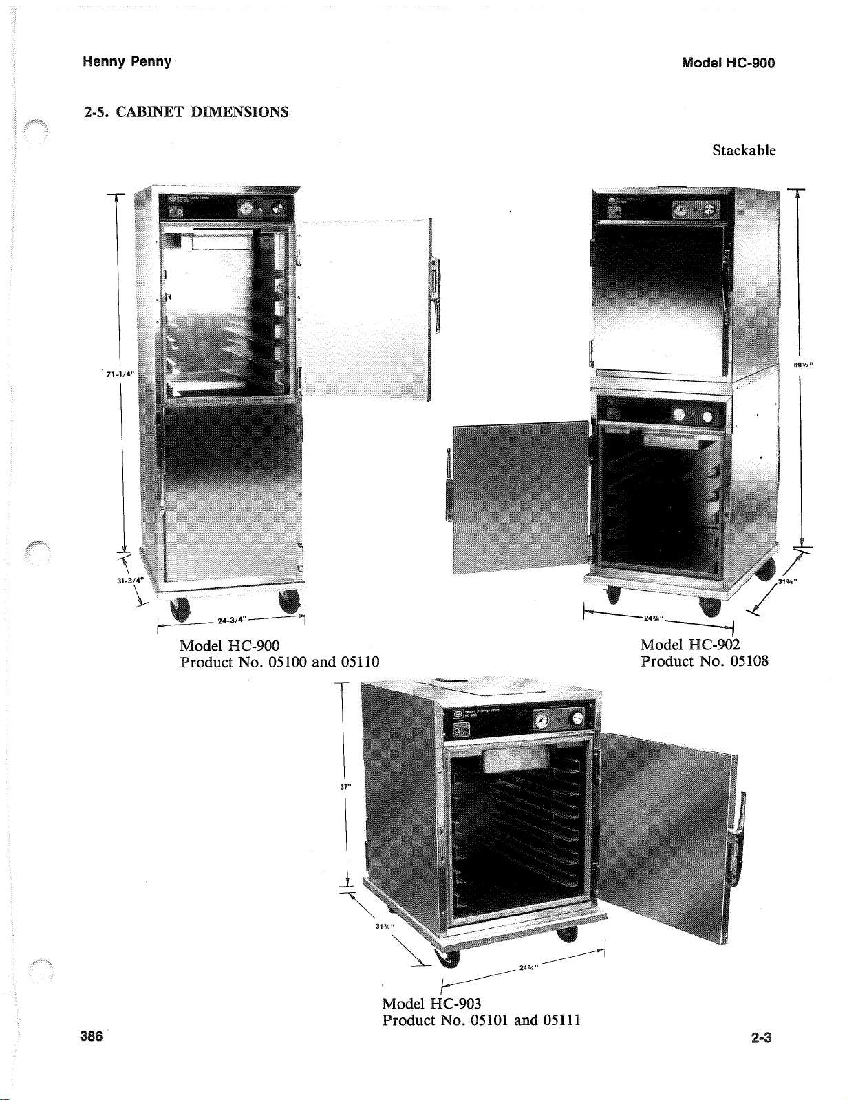
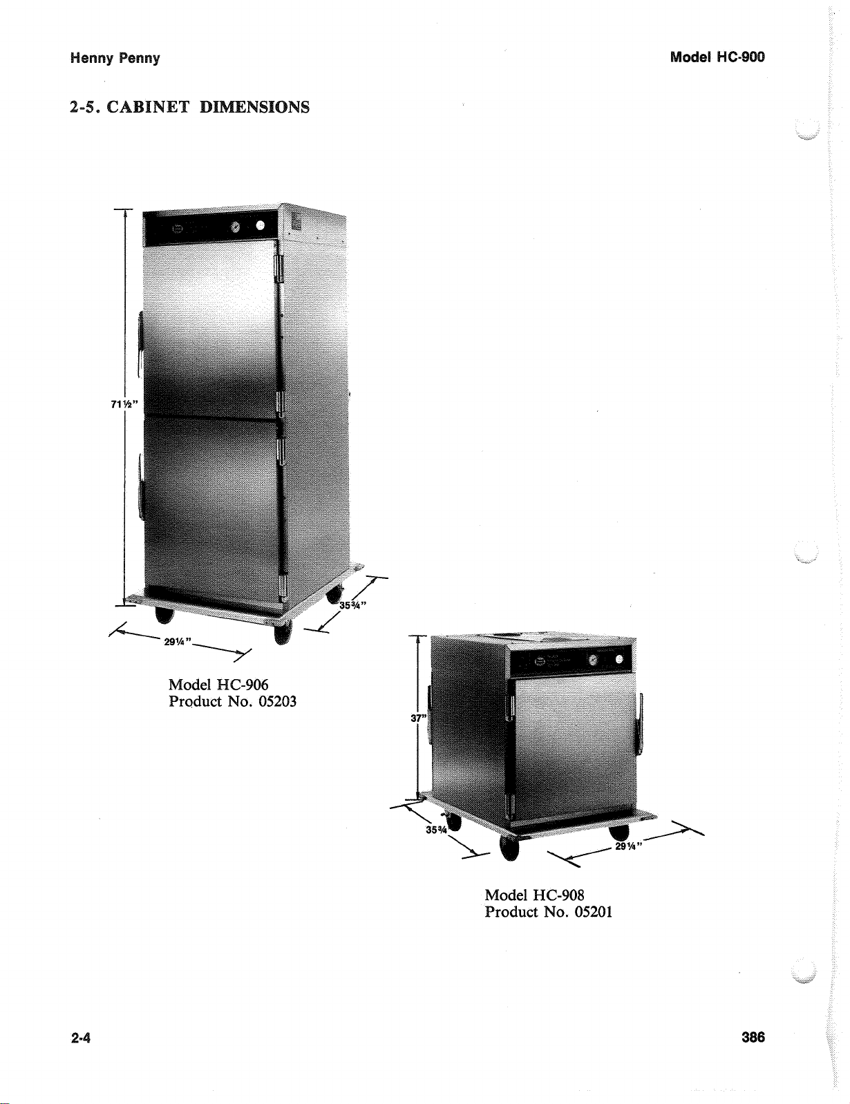
2-5. Cabinet Dimensions......................................................................................... 2-3
Section 3. OPERATION
3-1. Introduction ..................................................................................................... 3-1
3-2. Operating Controls and Components .............................................................. 3-1
3-3. Start-Up ........................................................................................................... 3-4
3-4. Operation with Product .................................................................................... 3-5
3-5. Vent Adjustments ............................................................................................. 3-5
3-6. Cleaning Procedures ........................................................................................ 3-5
3-7. Operating Controls 900 and 903 CDT (if applicable) ..................................... 3-7
3-8. Error Codes (CDT Controls) ........................................................................... 3-12
Section 4. TROUBLESHOOTING
4-1. Introduction ..................................................................................................... 4-1
4-2. Troubleshooting ............................................................................................... 4-1
Section 5. MAINTENANCE
5-1. Introduction ..................................................................................................... 5-1
5-2. Test Instruments ............................................................................................... 5-1
5-3. Removal of Module Access Panel ................................................................... 5-1
5-4. Module Removal ............................................................................................. 5-1
5-5. Module Housing Removal............................................................................... 5-2
5-6. Fuse.................................................................................................................. 5-2
5-7. Power Switch ................................................................................................... 5-3
5-8. Thermostat ....................................................................................................... 5-4
5-9. Indicating Lights .............................................................................................. 5-5
5-10. Thermometer ................................................................................................... 5-5
902 i
Y
ontinue
e
6.2
6.3
6.4
6.5
6.6
6.7
6.8
imit
.
Genuine Parts
.
How
to
.
.
.............................................................
.
.
.
..................................
........................................................
..........................................
.........................................
W
...............................
0
OOW
...............................
TION
60
60
HZ,
HZ,
150012000
3000 W
Z,
1612
3086W
2000 W
12
2086
W
.......................
............................
W
........................
............................
............................
w
............................
W
.............................
.......................................................
......................................................
Find Parts
Order
..................................................
......................................................
...........................................................
..........................................................
.........................................................
5-6
5-7
5-8
5-9
5-10
5-11
5-12
5-13
5-14
5-15
5-16
5-17
5-18
6-1
6-1
6-1
6-1
6-2
6-2
6-2
6-4
enny Penny Distributor ist (Domestic and International)
991

Henny Penny Model HC-900
SECTION 1. INTRODUCTION
1-1 HEATED HOLDING The Henny Penny Heated Holding Cabinet is a basic unit
CABINET (HC-900) of food processing equipment designed to hold hot foods at
proper temperature in commercial food operations. This
cabinet will keep hot foods humid while maintaining
temperature.
1-2 MODEL VARIATIONS This manual covers the following variations of the HC-900:
Product No. 05100 or 05110 Product No. 05101 or 05111
-Full Size Unit -HC-903
-4 Doors -120V/1500 Watt
-120V/2000 Watt -Vented Module
-Right (05100) or -Right (05101) or
Left Hand (05110) Left Hand (05111)
Hinged Doors Hinged Doors
Product No. 05102 Product No. 05103
-Full Size Unit -HC-903
-Features & Options -Features & Options
Product No. 05203 Product No. 05201
-HC-906 -HC-908
-Full Size 2 door -Single Door
-Vented Module -Vented Module
Some of the instructions and procedures in this manual will not
apply to all units.
1-3 FEATURES • Easily Cleaned
• Adjustable, Thermostatically Controlled Heat
• Lift-off Doors
• Easy Access to Electrical Components
• Moist Heat
• Removable Control Module
• Stainless Steel Construction
• Full Perimeter Magnetic Door Seals
• Lift Out Tray Racks
• UL & NSF Listed
• Venting System to Limit Humidity Levels in Cabinet (Units
with vent adjustment).
• Optional Adjustable Legs.
• 200 lbs. (91 kgs) Product Capacity
-Vented Module
299 1-1

Henny Penny Model HC-900
1-4 PROPER CARE As in any unit of food service equipment, the Heated Holding
Cabinet does require care and maintenance. Suggestions for the
proper care and maintenance are contained in this manual.
For your convenience, this manual consists of the following
sections:
! Table of Contents
! Introduction
! Installation
! Operation
! Troubleshooting
! Maintenance
! Wiring Diagrams
! Part List
! Distributor List
The conscientious use of the recommended procedures, coupled with
regular maintenance, will result in few repairs to the equipment.
When such repairs are required, they may be accomplished by following the repair steps contained in this manual.
1-5 ASSISTANCE Should you require outside assistance, just call your local indepen-
dent distributor maintained by Henny Penny Corporation.
In addition, feel free to contact our corporate headquarters in Eaton,
Ohio. Dial 800-417-8405, or 937-456-8405.
1-6 SAFETY The only way to insure safe operation of the Henny Penny Heated
Display Cabinet is to fully understand the proper installation,
operation, and maintenance procedures. The instructions in this
manual have been prepared to aid you in learning the proper
procedures. Where information is of particular importance or is
safety related, the words NOTE, CAUTION or WARNING are
used. Their usage is described below:
NOTE
The word NOTE is used to highlight especially important information.
1-2 299
enny Penny
1-6
SAFETY
(Cont.)
The word CAUTION
is
used to alert you to a procedure that, if
not performed properly, may damage the unit.
The word WARNING
is
used to alert you to a procedure that, if
not performed properly, might cause personal injury.
0682
-3

enn
y
Penny
2-1
~TRODUCTI
SECTION
2.
~ST~LATION
This section provides
Henny Penny Heated
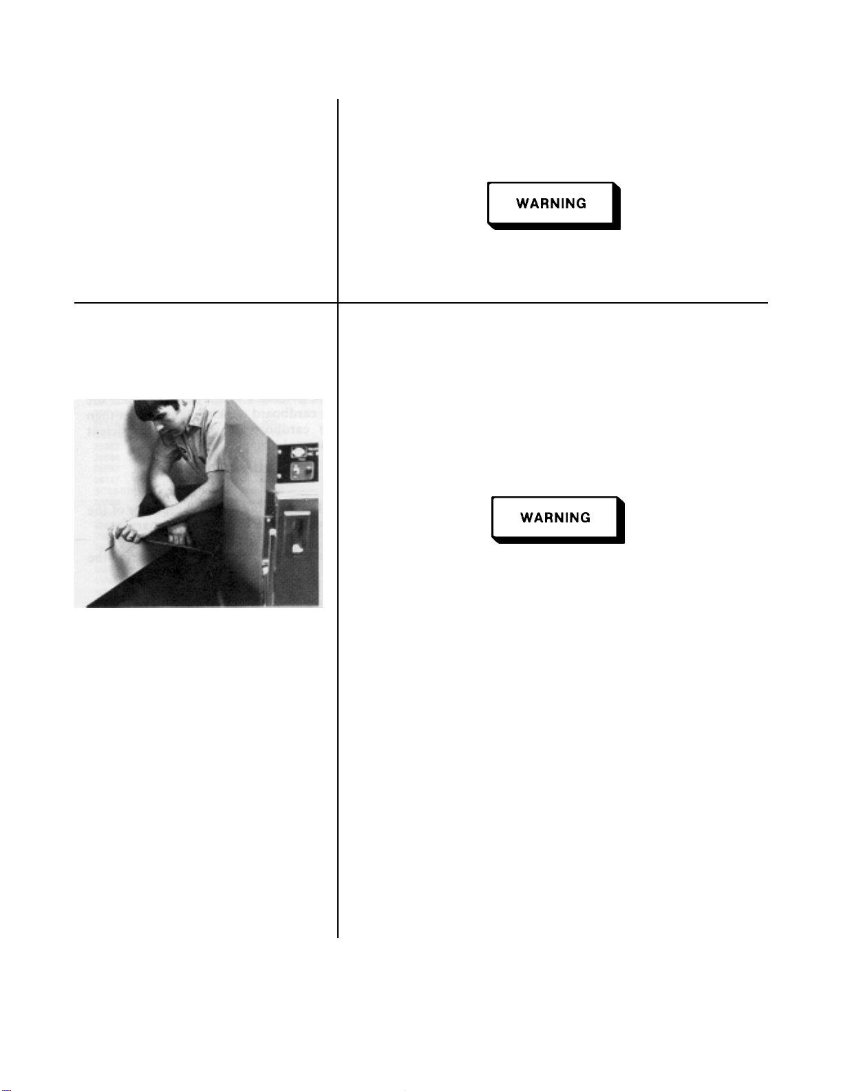
Installation of this unit should be performed only by a qualified
service technician.
Do
not puncture the skin
drills or screws as component damage or electrical shock could
result.
inspected, and expertly packed to insure arrival at its
destination in the best possible condition. The cabinet rests on
cardboard pads that sit on a wooden skid. The racks inside the
cabinet are secured with cardboard packing. The unit
packed inside a heavy cardboard carton with sufficient
padding to withstand normal shipping treatment.
installation instructions for the
of
the olding Cabinet with
olding Cabinet has been tested,
is
then
Any shipping damages should be noted in the presence
delivery agent and signed prior to his or her departure.
To remove the Henny Penny
carton, you should:
1.
Carefully cut banding straps.
2.
Lift the carton off the unit.
3.
Lift the unit off the cardboard padding and skid.
Care should be taken when lifting unit to prevent personal injury.
4.
Open doors and remove packing from behind racks.
5.
Peel off any protective covering from the exterior of the
cabinet.
6.
Your Heated Holding Cabinet is now ready for location and
set up.
Be certain to save any literature that is packed inside the
cabinet.
olding Cabinet from the
of
the
5
Henny Penny Model HC-900
2-3 LOCATION The HC-900 should be placed in an area where the doors can
be opened without interruption and loading and unloading of
product is easy. For proper operation, the cabinet must be level.
Do not set anything on top of the cabinet that might close
the vent holes.
2-4 ELECTRICAL CONNECTION The Heated Holding Cabinet is available from the factory as a
120 VAC or 240 VAC unit for domestic use and as a 240 VAC
unit for foreign use. The data plate, located on the side of the
module, will specify the correct electrical supply. The unit
requires a grounded receptacle with a separate electrical line
protected by a fuse or circuit breaker of the proper rating. For
European markets, verify the electrical plug meets the proper
electrical rating and country type. See local authorities for
proper standards.
The cabinet must be adequately and safely grounded
according to local electrical codes to prevent the possibility
of electrical shock.
Refer to the table below for electrical ratings for the HC-900.
Product Number Volts Watts Amps
05100 or 05110 120 2086 17.5
Full Size (Standard)
05101 or 05111 120 1586 13.0
HC-903 (Standard)
05102 Full Size 240 3086 13.0
05102 Full Size 240 2086 9.0
05103 (HC-903) 240 3086 13.0
05103 (HC-903) 240 2086 9.0
05108 (HC-902) stackable 120 1586 13. 0
05203 (HC-906) 120 2086 17.5
05201 (HC-908) 120 2086 17.5
2-2 1098
-5.
ENS
S
tackable
00
05100
and
05110
-906
0.
05203
Model
Product
HC-908
No.
05201
enny Penny
N
__
TRODUCTION
-2
CONTROL§
NENTS
This section provides operating procedures for the
Sections 1,2 and
3
should be read, and all instructions should
be followed before operating the cabinet.
This section contains an explanation of all controls and
components and information on operating procedures and
daily maintenance.
Figures
3-1
through
3-5
identify and describe the functio? of all
the operating controls and the major components of the
cabinet.
2
1
9"
'8
d
e-90
3-
1
3-1 2
3-1
1
3-
3-
3-2
3
4
5
6
eserip
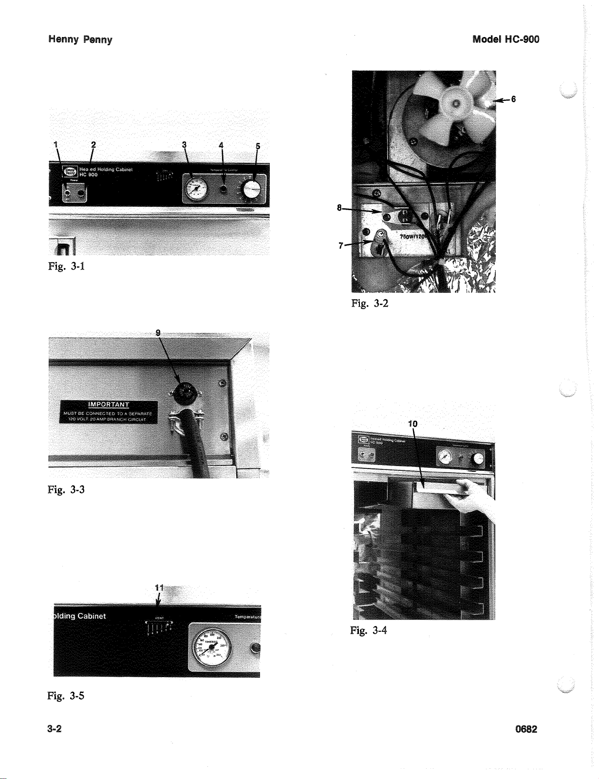
Power Switch The power switch
Thermometer
eat Light
hermostat
i
electrical current to the unit.
When illuminated, the pow light indicates that the
power switch is in the
components are energized.
The thermometer indicates the air tempeiature
inside the cabinet.
When illuminated, the heat light indicates that the
thermostat has turned the heaters on.
The thermostat is an electromechanical device that
controls the temperature inside the cabinet.
I
I
re are two blower motor assemblies in the
-900.
The blower motors are used to recirculate
the hot humid air throughout the cabinet.
is
a toggle switch that switches
‘
N”
position and the
3-2
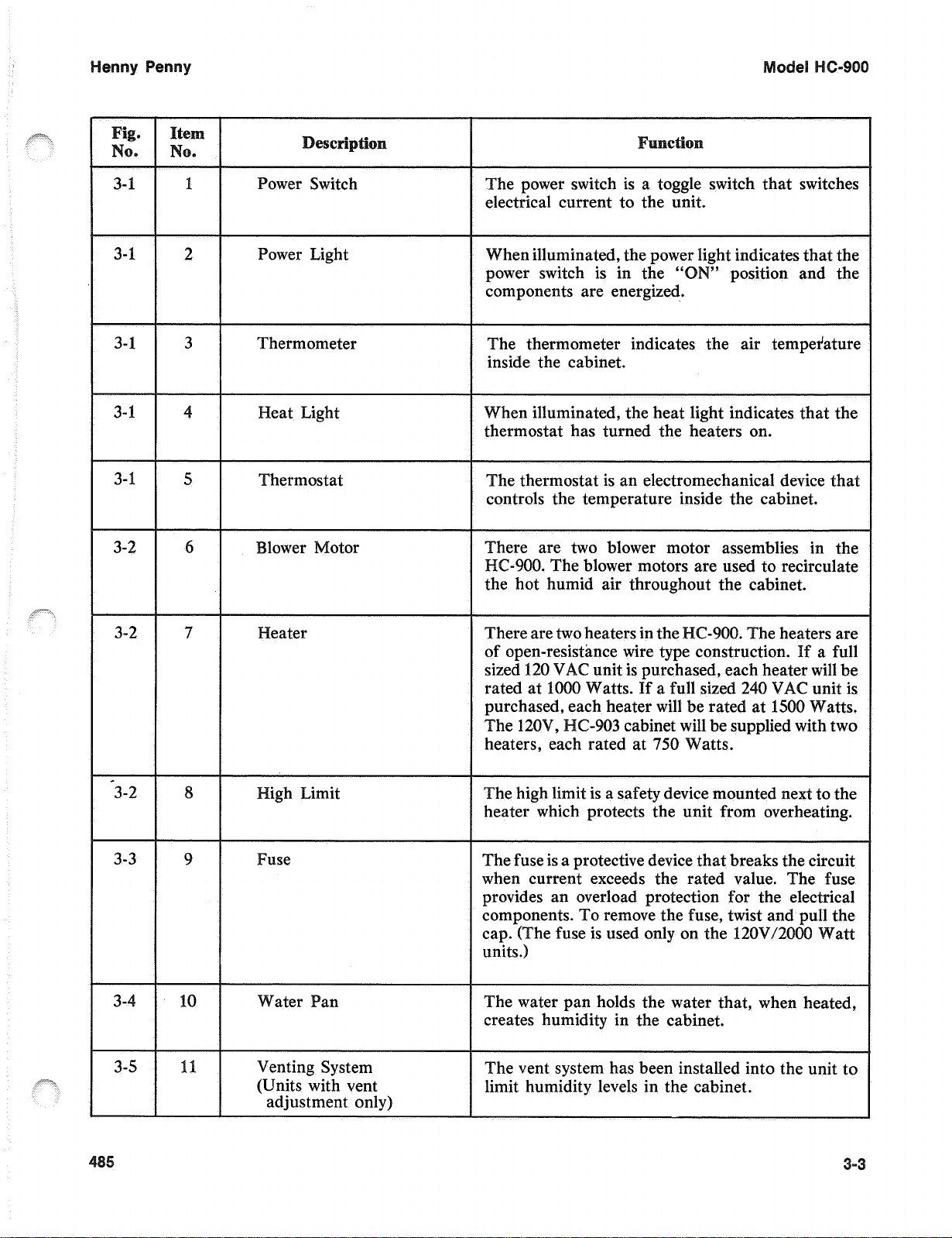
7
3-2 8
3-3
3-4
9
10
3-5 1
eater
igh Limit he high limit is a safety device mounted next to the
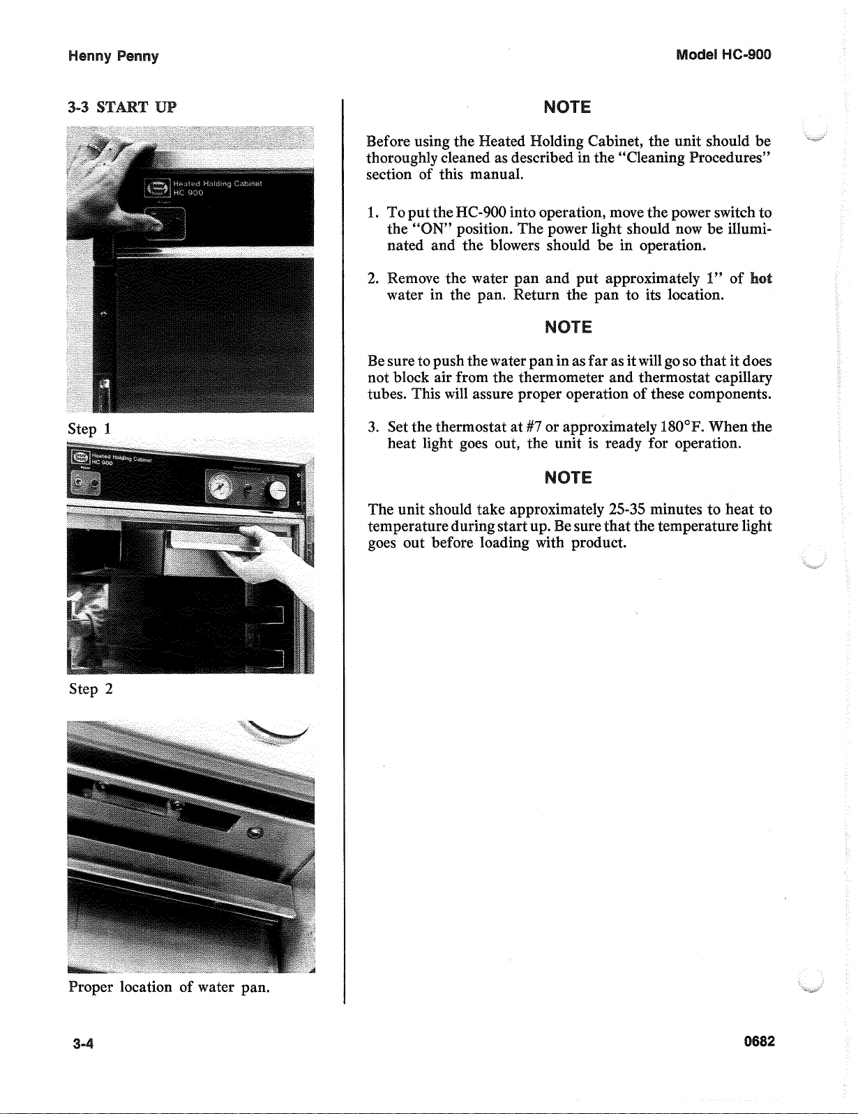
use
Venting System
(Units with vent
adjustment only)
There are
of open-resistance wire typ
sized
rated at
purchased, each heater will be rated at
heaters, each rated at
heater which protects the unit from overheating.
he fuse is a protective device that breaks the circuit
when current exceeds the rated value.
provides an overload protection for the
units.)
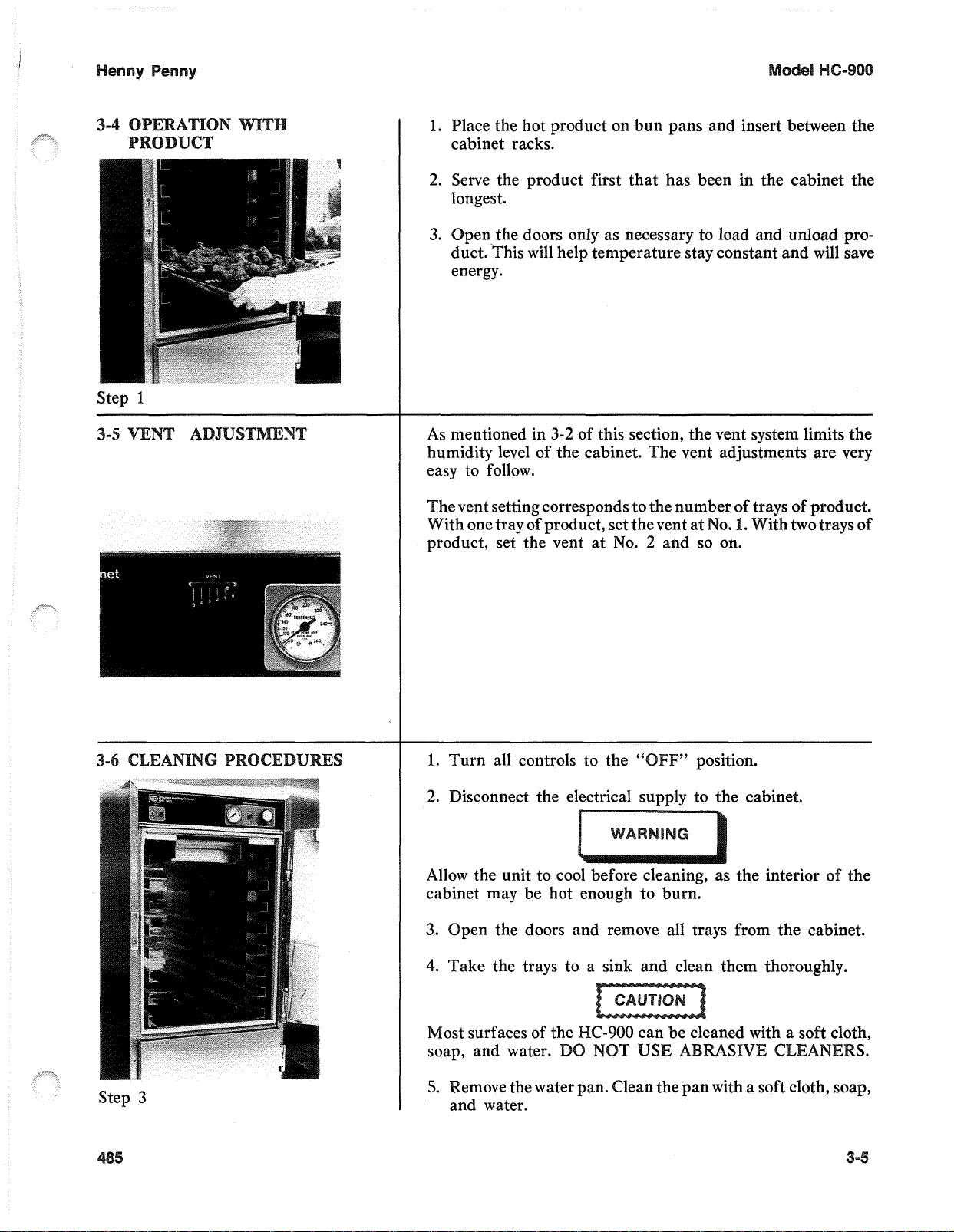
The water pan holds the water that, when heated,
creates humidity in the cabinet.
The vent system has been installed into the unit to
limit humidity levels in the cabinet.
two
heaters in the
120
VAC unit is purchased, each heater will be
1000
Watts. If a full sized
240
VAC unit is
1500
C-903
cabinet will be supplied with two
750
Watts.
o
remove the fuse, twist and pull the
is used only on the
120V/2000
Watts.
3-
6-
Stet,
1
efore using the
olding Cabinet, the unit should be
thoroughly cleaned as described in the “Cleaning
section of this manual.
1.
the
HC-900
N”
position. The power light should now be illumi-
into operation, move the power switch to
nated and the blowers should be in operation.
1”
emove the water pan and put approximately
of
water in the pan. Return the pan to its location.
e sure to push the water pan in as far as it will go
so
that it does
not block air from the thermometer and thermostat capillary
his will assure proper operation of these components.
3.
Set the thermostat at
#7
or approximately 180”
heat light goes out, the unit is ready for operation.
25-35
he unit should take appro
temperature during start up
ately
sure that the temperature light
minutes to heat to
goes out before loading with product.
Step
2
roper location of water pan.
3-
2
I
Y Y
1.
Place the hot product on bun pans and insert between the
cabinet racks.
2.
Serve the product first that has been in the cabinet the
longest.
3.
Open the doors only
as
necessary to load and unload product. This will help temperature stay constant and will save
energy.
Step
1
3-2
-5
As mentioned in
of this section, the vent system limits the
humidity level of the cabinet. he vent adjustments are very
easy to follow.
The vent setting corresponds to the number of trays of product.
No.
1.
With one tray of product, set the vent at
No.
2
and
product, set the vent at
so
With two
on.
trays
of
Step
3
urn all controls to the
2.
Disconnect the electrical supply to the cabinet.
" "
position.
Allow the unit to cool before cleaning, as the interior of the
cabinet may be hot enough to burn.
pen the doors and remove all trays from the cabinet.
4.
Take the trays to a sink and clean them thoroughly.
Most surfaces of the
soap, and water.
5.
Remove the water pan. Clean the pan with a soft cloth, soap,
D
and water.
Y
Henny Penny Model HC-900
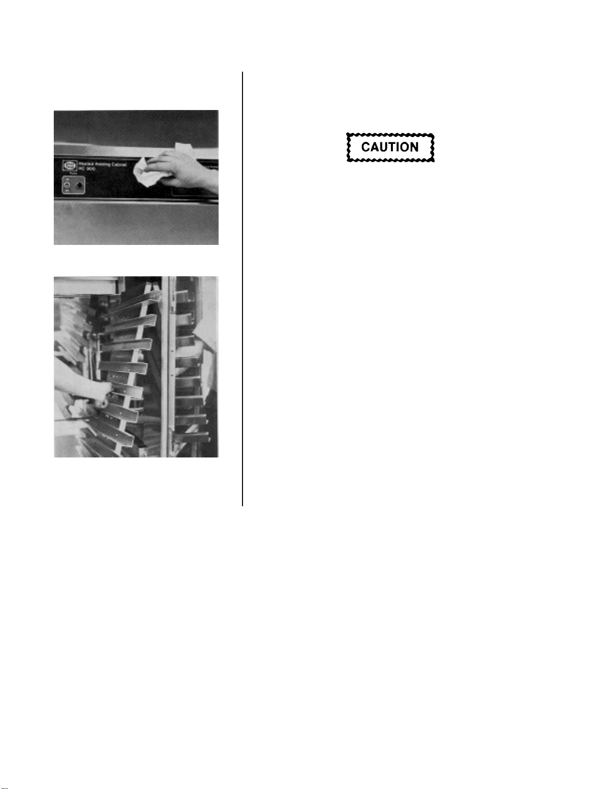
3-6 CLEANING PROCEDURES 6. Wipe the control panel with a damp cloth. Do not splash
(Cont.) water around the controls.
7. Clean the exterior of the cabinet with a damp cloth.
DO NOT use a spray hose to clean the unit. Failure to
follow these instructions could cause component damage.
8. Open the doors and remove side racks. Clean the racks
with soap and water.
Step 6 9. Clean the interior of the cabinet thoroughly with a cloth
and soap water.
10. Put the side racks and water pan back into the cabinet.
Step 8
11. Leave at least one door open over night to allow the unit to
thoroughly dry out.
3-6 1298
 Loading...