

OPERATION & MAINTENANCE GUIDE -
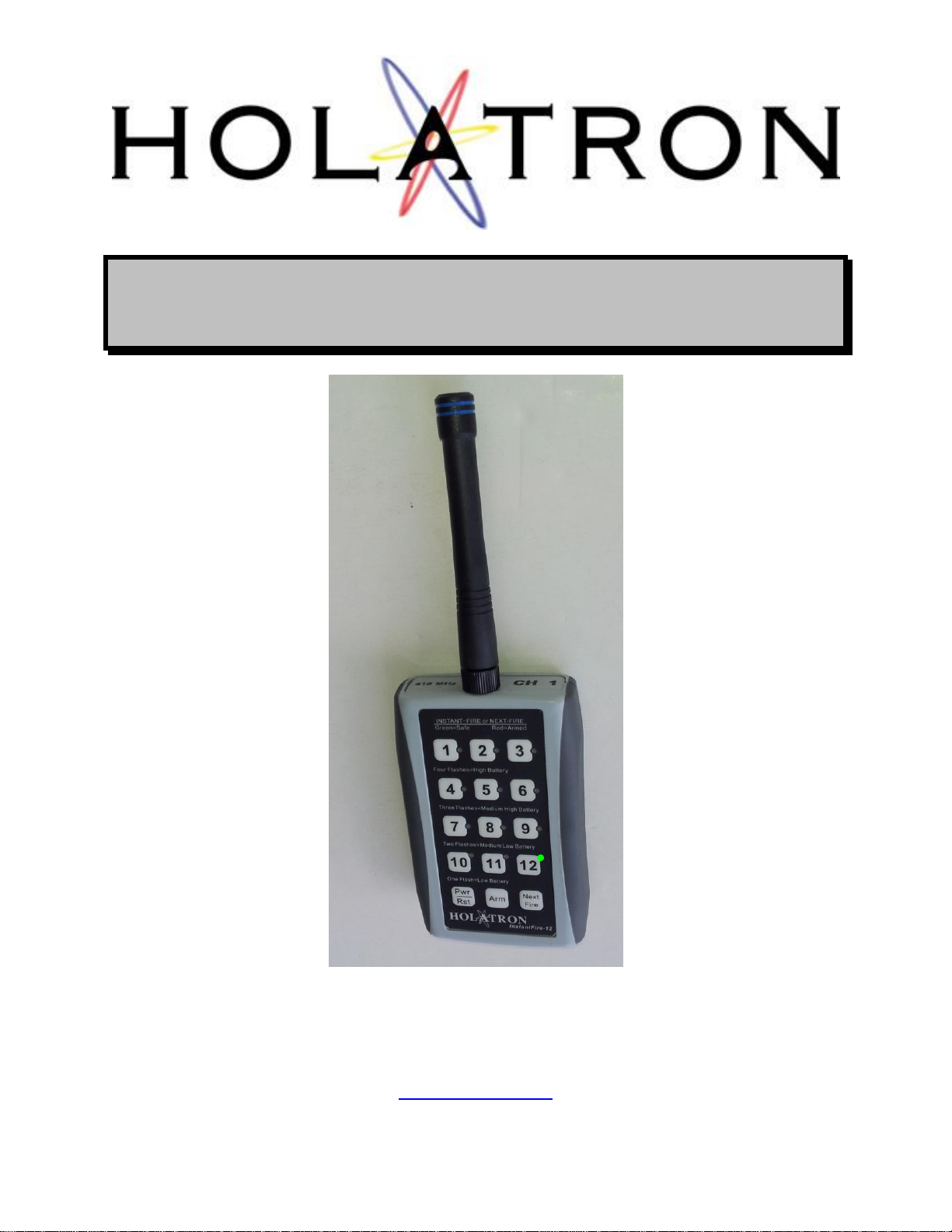
InstantFire-12B
High-speed 12-shot Controller
HOLATRON SYSTEMS, LLC
833 ILANIWAI ST, STE. 2
Honolulu, HI 96813
(808) 372-0956
www.holatron.com

WARNING
Holatron Systems specializes in the design and manufacture of standard and custom electronic
control systems where reliability and error free data communication are critical. The transmitter
described in this manual is part of a system intended to remotely actuate pyrotechnic or other
hazardous devices, and the components of this system have been carefully designed to
minimize the possibility of accidental actuation of such devices. Holatron’s design goal is to
ensure that data communication errors due to radio interference or to insufficient signal strength
due to low battery, exceeding specified range, or conductive objects in the signal path will result
in failure of intentional actuation rather than unintended actuation. Techniques used to achieve
this design goal are described in section 2.0. Though the probability of unintended actuation is
extremely small, it cannot be guaranteed to be zero. It is also possible that an unexpected
actuation can occur if another Holatron transmitter set to the same digital channel and
system code is being operated in the vicinity. Therefore, it is important that the user not
enable (arm) the receiver until all persons who might be harmed by accidental actuation
are in a safe area.
Equipment that has been damaged or contaminated internally with water or other substances
could be hazardous to operate, and it could generate an unintended actuation. The user must
consult with Holatron Systems before continuing use of such equipment.
As a condition of purchase, the user must acknowledge awareness and agreement that
utilization of this product and participation in activities utilizing compressed gas, fireworks,
rockets, explosives, etc. is an ultra-hazardous activity carrying implied and explicit risks of
injuries and damages to the user and to other participants. The us er assumes the risk
connected with the utilization of this product and all risks of participation in the activities for
which this product is sold. User acknowledges that he/she/it has the necessary and required
skill, expertise, training and licensing, as may be applicable or necessary by custom, usage,
trade or law, to engage and participate in the ultra-hazardous activities connected with the use,
purchase, transportation, or employment of the products sold under this agreement. User
acknowledges that Holatron Systems, LLC, has not and will not conduct any investigation into
the skill, expertise, training and licensing, as may be applicable or necessary by custom, usage,
trade or law, of the user or of user’s agents, employees and assigns, to engage and participate
in the ultra-hazardous activities connected with the use, purchase, transportation, or
employment of this product. User specifically agrees that Holatron Systems, LLC, its officers,
employees, and agents shall not be liable for any claim, demand, cause of action of any kind
whatsoever for, or on account of death, personal injury, property damage or loss of any kind
resulting from or related to user’s or user’s employees’, agents’ or assigns’ use of this product,
and user agrees to indemnify, defend in any action at law, and hold harmless Holatron Systems,
LLC, from same, whether brought by the user, user’s agent, or assigns, or any third party.
2 of 11

INFORMATION TO USER
This device complies with Part 15 of the FCC Rules. Operation is subject to the following two
conditions: (1) This device may not cause harmful interference, and (2) This device must
accept any interference received, including interference that may cause undesired operation.
This equipment has been tested, assigned FCC ID number OI4XMTR12B, and found to comply
with the limits for Class B Digital Device, pursuant to Part 15 of the FCC Rules. These limits are
designed to provide reasonable protection against harmful interference in a residential
installation. This equipment generates and can radiate radio frequency energy and, if not
installed and used in accordance with the instructions, may cause harmful interference to radio
communications. However, there is no guarantee that interference will not occur in a particular
installation. If this equipment does cause harmful interference to radio or television reception,
which can be determined by turning the equipment off and on, the user is encouraged to try to
correct the interference by one or more of the following measures.
· Reorient or relocate the receiving antenna
· Increase the separation between the equipment and receiver
· Connect the equipment into an outlet on a circuit different from that to which the receiver
is connected
· Consult the dealer or an experienced radio/TV technician for help
Any changes or modifications not expressly approved by the party responsible for compliance
could void the user’s authority to operate the equipment.
Les changements ou modifications non approuvés expressément par la partie responsable de
la conformité pourrait annuler l'autorité de l'utilisateur à faire fonctionner l'équipement..
This device also complies with Industry Canada licence-exempt RSS standard(s). Operation is
subject to the following two conditions: (1) this device may not cause interference, and (2) this
device must accept any interference, including interference that may cause undesired operation
of the device.
Le présent appareil est conforme aux CNR d'Industrie Canada applicables aux appareils radio
exempts de licence. L'exploitation est autorisée aux deux conditions suivantes : (1) l'appareil ne
doit pas produire de brouillage, et (2) l'utilisateur de l'appareil doit accepter tout brouillage
radioélectrique subi, même si le brouillage est susceptible d'en compromettre le
fonctionnement.
This radio transmitter 11556A-XMTR12B has been approved by Industry Canada to operate
with the antenna types listed below with the maximum permissible gain and required antenna
impedance for each antenna type indicated. Antenna types not included in this list, having a
gain greater than the maximum gain indicated for that type, are strictly prohibited for use with
this device.
Le présent émetteur radio 11556A-XMTR12B a été approuvé par Industrie Canada pour
fonctionner avec les types d'antenne énumérés ci-dessous et ayant un gain admissible maximal
et l'impédance requise pour chaque type d'antenne. Les types d'antenne non inclus dans cette
liste, ou dont le gain est supérieur au gain maximal indiqué, sont strictement interdits pour
l'exploitation de l'émetteur.
This radio transmitter is approved for operation with Linx Technologies ANT-418-CW-HD
monopole antenna with RP-SMA connector and peak gain of -1.8 dBi.
3 of 11

This manual is divided into four sections. The first is a description of the system hardware. The
second describes radio interference suppression methods. The third lists system specifications.
The fourth covers the recommended operating and maintenance procedure.
1.0 HARDWARE DESCRIPTION.
The model XMTR12B high-speed 12-shot controller is a low power hand-held remote
control transmitter which can transmit commands over any of twelve different digital
channels. Each transmitter’s default channel setting (base channel) is fixed in software
at time of manufacture, and this is the channel on which it begins operation at power-on.
Operation can subsequently be switched to a different channel by pressing the Pwr / Rst
button, followed by the number of the desired new channel. A label displaying the default
channel setting (base channel) is affixed to the top of the transmitter next to the antenna.
Transmitters operating on separate digital channel numbers can transmit simultaneously
without interfering with each other. This permits up to twelve different receivers or
groups of receivers to be controlled by separate transmitters simultaneously. A
transmitter will only actuate receivers whose digital channel switches are set to select
the same channel as the transmitter. Thus, multiple transmitters may be used to actuate
different selected receivers even though all operate on the same frequency. Transmitters
operating on the same digital channel number should not be used simultaneously, as
they will interfere with each other and possibly result in failure-to-fire.
When used with RFLS-491HSRC, RFLS-96HSRC, RFLS-96HSARC, RFLS-496HSRC,
RFLS-496HSARC, RFLS-912HSRC, RFLS-912HSARC, or RFLS-91212HSRC
receivers, a range of ½ mile can be achieved. All inscriptions on the transmitter panel
are luminescent to facilitate use of the transmitter in a dark environment. The panel will
continue to glow for two to three hours after being exposed to a bright light source. The
transmitter’s commands are digitally encoded and amplitude modulated on a single
carrier frequency of 418 MHz (or 433.96 MHz in Europe). This frequency is synthesized
via phased-locked-loop from a quartz crystal for exceptional stability and immunity to
antenna proximity effects. No alignment or tuning procedures are ever required to
maintain optimum performance. The modulated RF output occurs continuously while a
transmit button is depressed. Resulting receiver output is continuous while the button
command signal is being transmitted. The command signal is transmitted by amplitude
modulating the carrier to indicate to the receiver which of the transmit buttons is
depressed.
The transmitter turns off its power automatically after 45 minutes of inactivity in order to
prevent accidental depletion of its batteries while in storage.
4 of 11

The user has access to the following components:
1.1 THE ANTENNA.
The RF signal is radiated by a quarter-wave reduced height helical antenna
which screws onto the top end of the transmitter box. The transmitter should
never be operated without this antenna in place, as damage to the RF
components could result. Such operation will void the warranty.
Antennas with red rings are used for 433 MHz, and antennas with blue rings are
used for 418 MHz. Be sure to use an antenna that matches the transmitter
frequency, or range will be seriously degraded. Be careful not to overtighten the
antenna when screwing it on, as this could put excessive stress on the internal
connections to the mating connector. The recommended way to install the
antenna is to grasp it by its small diameter upper part and rotate gently in a
clockwise direction until increased resistance is felt. It need not be very tight to
achieve a good electrical connection. The antenna can be removed for storage.
1.2 THE PWR / RST BUTTON.
This is a dual function button. It can turn the transmitter power on and off, or it
can initiate the transmitter’s reset (channel-change) function, depending on how
and when it is pressed. The transmitter reset function is described in section 1.6.
The power on/off function is described here.
When the transmitter is off, all indicators are dark, and no signals can be
transmitted even if a button is pressed. When the transmitter is on, one of the 12
indicators will light to indicate the current transmitter state, as described in the
last paragraph of this section.
If the transmitter is off, pressing this button instantly turns power on, with the
transmitter initialized to cue 1. If the transmitter is on, pressing and holding this
button for at least 0.75 second turns power off.
The transmitter turns off its power automatically after 45 minutes of inactivity in
order to prevent accidental depletion of its batteries while in storage.
Pressing the Pwr / Rst button for less then 0.5 second while the transmitter is on
places the transmitter in channel-change mode, as indicated by a continuously
illuminated cue indicator. The transmitter will switch to the channel number
selected by the next numerical button press, and the cue number for that channel
will be reset to 1. If more than 4 seconds elapses without a button press after
channel-change mode is entered, the transmitter will revert to its previous
flashing mode without affecting channel or cue number. If the Pwr / Rst button is
pressed instead of a numerical button within the 4 second timeout period,
channel-change mode is canceled, but operation of the transmitter and receiver
is reset to cue 1 so that the next depression of the “Fire Next” button will fire
receiver output 1 on the current channel. This causes transmission of a RESET
command to all receivers set to the transmitter’s digital channel. This feature is
useful for restarting automatic-fire sequences from cue 1. It does not affect the
function of the numeric keys or the ARM state of the transmitter.
5 of 11

1.3 THE “TRANSMITTER STATUS” INDICATORS.
When the transmitter is on, one of the 12 cue indicators will light to indicate the
current cue number, armed state, and battery level.
If flashing red, the lighted indicator warns the user that the transmitter is armed
and currnet cue fire command transmission will occur when a button is pressed.
If flashing green, it indicates that the transmitter is not armed and that no
transmission will occur if a button is pressed.
It also verifies that battery voltage is adequate by flashing periodically in bursts of
two, three, or four flashes per cycle if the transmitter is in single-shot mode. A
cycle lasts approximately one second. If fewer than two flashes per cycle are
occurring, the batteries must be replaced before the transmitter can be used
reliably. Four flashes per cycle indicate that the batteries have full capacity, three
flashes indicate that their capacity is beginning to diminish, and two flashes
indicate that they are near the end of their useful lifetime in which case they
should be replaced immediately after the current use. Adequate transmitter
output to achieve the specified range will occur as long as the total series battery
voltage is above approximately 2.0 volts, but the battery voltages will drop rapidly
at this point.
If the transmitter is set to auto-fire (machine-gun) mode, the current cue indicator
will flash continually at the selected automatic fire rate instead of indicating
battery level.
This lamp lights continuously while in channel-change mode (after momentarily
pressing the Pwr / Rst button), and it also serves as a transmit indicator by
lighting continuously red while transmission is occurring.
1.4 THE FIRE BUTTONS.
These buttons are snap action dome switches under a sealed overlay. The
transmitter is idle while no buttons are pressed. If armed, continuous
transmission occurs while “Next Fire” or a numeric button is pressed.
Depression of “Next Fire” (while armed) fires the next receiver output after the
one fired last. For example, if output 3 had been fired last, pressing “Next Fire”
would cause output 4 to fire. If output 12 had been fired last, pressing “Next Fire”
would cause output 1 to fire. Thus, “Next Fire” can be used to fire a series of
sequential shots. Note that after powering up the transmitter, output 1 will be the
first receiver output fired by a depression of the “Next Fire” button.
If in single-shot mode, the current cue will continue firing until the transmitter
button is released. If in auto-fire (machine-gun) mode, the transmitter will
continue firing cues sequentially at the selected fire rate until the “Next Fire”
button is released. After firing cue 12, the transmitter will wrap around to cue 1
and continue firing from there.
Pressing a numeric button (while armed) fires the corresponding receiver output
immediately.
6 of 11

Output firing pulses are stretched to a minimum duration of 0.6 seconds in the
receivers to ensure that all cues fire reliably, even when the fire buttons are
pressed for a shorter period of time. Note that it is not necessary to wait for the
completion of the 0.6 second firing pulse period before firing subsequent cues.
They can be fired as fast as the operator can press the button, provided that
each button depression lasts at least 0.1 second, followed by at least 0.1 second
with the button released. If many transmitters are transmitting simultaneously, it
may be necessary to depress a fire button slightly longer than 0.2 second in
order to ensure an output from the receiver.
1.5 THE ARM BUTTON.
Each successive depression of this button advances the transmitter to the next of
four firing modes: “Safe”, “Armed (single shot)”, “Armed (auto-fire low rate)”, and
“Armed (auto-fire high rate)”. The next button depression after “Armed (auto-fire
high rate)” returns the transmitter to “Safe” mode, and the sequence then
repeats. This button must be pressed after power-on to enable transmission of
firing commands since the transmitter always powers up in a disarmed state.
1.6 THE BATTERIES.
Power is supplied from two AA 1.5 volt batteries, accessible beneath a slide-out
door on the back side of the transmitter. These batteries should be replaced
when required by conditions described in section 1.3 above. In order to prevent
the possibility of damage due to battery leakage, the batteries should always be
removed if the transmitter is to be stored for a prolonged period. Damage due to
battery leakage is not covered under the warranty. Be sure to observe proper
battery polarity as marked inside the battery compartment.
The transmitter turns off its power automatically after 45 minutes of inactivity in
order to prevent accidental depletion of its batteries while in storage.
7 of 11

2.0 RADIO INTERFERENCE REDUCTION.
For obvious safety reasons, Holatron's design goal is to ensure that data
communication errors due to radio interference or to insufficient signal strength
due to low battery, exceeding specified range, or conductive objects in the signal
path will result in failure of intentional actuation rather than unintended actuation.
This goal is achieved by transmitting a 64 bit noise-tolerant code repeatedly while
a transmitter button is depressed. 60 of these bits must match the pattern
expected by the receiver. Thus, there is one chance in (2 to the 60
actuation occurring due to reception of a random signal. Expressed in decimal
numbers, this is (1.1529 times 10 to the 18th power, or 11529 followed by 14
zeroes). This is a probability of 8.6736 times 10 to the -19th power (or a decimal
point followed by 18 zeroes followed by 86736). Though this probability of
unintended actuation is extremely small, it cannot be guaranteed to be zero.
Therefore, it is important that the user not arm the receiver until all persons
who might be harmed by accidental actuation are in a safe area.
Additional protection is offered by use of 418 MHz as the operating frequency.
This frequency is sparsely used only by low power transmitters with a maximum
range of approximately 100 yards. It is not commonly used by auto security
systems, garage door openers, radio control models, cordless or cellular
telephones, wireless microphones, or two way communications equipment.
Because this system operates in the UHF region, interference from lamp
dimmers, electrical discharges, and other natural sources is also minimal.
No instances of unexpected actuation with this communications technology have
been reported to date, but the user must consider that radio is a shared medium.
It is very important to know what other wireless devices are operating in the
vicinity of this equipment. Interference from non-Holatron equipment can result in
diminished range or failure-to-fire, and interference from other Holatron
devices operating on the same channel and with the same system code can
result in unexpected actuation. To be protected from this possibility, the user
must request a proprietary system code from Holatron when ordering.
th
power) of an
8 of 11

Parameter
Minimum
Typical
Maximum
Carrier Frequency, MHz. (US, Canada)
417.97
418.02
418.07
Carrier Frequency, MHz. (Europe)
432.91
433.96
434.01
Range (line-of-sight with RFLS-96RC 496RC & RFLS-912HSRC receivers)
½ mile
Delay from start of button depression
to receiver output (fewer than 4
transmitters transmitting
simultaneously)
50 msec.
75 msec.
Delay from start of button depression
to receiver output (more than 3
transmitters transmitting
simultaneously)
100 msec.
400 msec.
Button depression time per cue (fewer
than 4 transmitters transmitting
simultaneously)
100 msec.
Button depression time per cue (more
than 3 transmitters transmitting
simultaneously)
400 msec.
Battery current, standby, (power off)
Battery current, average, (power on)
Battery current, average, (xmting)
1 uA
1.0 mA
4.0 mA
Battery life (power on, not transmitting)
Battery life (power off)
4 months
5 years
Inactivity power-down timeout
45 min.
Low Battery Detect Threshold
2.0 V
Transmitter Supply Voltage
1.8 V
3.6V
3.0 SPECIFICATIONS.
4.0 OPERATION AND MAINTENANCE.
This section describes the recommended operating procedure and maintenance for the
transmitter-receiver system.
4.1 OPERATION.
4.1.1 Turn on and arm the transmitter, and with the receiver’s ARM switch in
“safe” or “disarmed” position and no devices connected, perform a
range test by observing the green activity light on the receiver while
pressing a numeric transmitter button. An assistant may be needed to
observe the receiver activity light while you operate the transmitter. There
should be no intervening conductive objects for most reliable operation.
All receivers must be elevated 12” or more above ground level to achieve
specified range. When transmitting over water, range will normally exceed
the specified value. Range of the receiver is typically ½ mile.
Verify that the transmitter battery is not depleted by observing the flashing
“Battery Level” light while not pressing the FIRE buttons. (See section
1.3) Then turn the transmitter off.
9 of 11

4.1.2 With the receiver turned off and its arm switch set to “disarm” (RFLS-
496HSRC or RFLS-496HSARC) or “safe” (RFLS-96HSRC, RFLS96HSARC, RFLS-912HSRC, RFLS-912HSARC, or RFLS-91212HSRC),
connect devices to the receiver outputs.
4.1.3 With the arm switch still in the previous position, turn on the receiver.
Verify a flashing green battery indicator on the receiver module. On an
RFLS-912HSRC, RFLS-912HSARC, or RFLS-91212HSRC receiver, this
indicator will flash intermittently in bursts of two, three, or four flashes at a
time if the battery has enough capacity to power the receiver. If only one
flash occurs per burst, the receiver cannot be used reliably. Four flashes
per burst indicate that the battery is fully charged, three flashes indicate
that its charge is beginning to diminish, and two flashes indicates that it is
near the end of its useful charge, in which case it should be replaced
immediately after the current use. On the other receiver models, there will
be one fewer flash per burst for the same condition.
4.1.4 When the area around the devices to be actuated is clear of persons who
might be injured by an accidental actuation, and after verifying that the
receiver’s green activity light is off (no radio signal is being detected), turn
the receiver’s ARM switch to its “Armed” position. Refer to the receiver
manual for the detailed arming procedure.
WARNING - If the receiver’s green activity light is erratic or on
continuously, its outputs may be actuated immediately upon changing its
ARM switch to the “Armed” position.
Do not arm a receiver with connected devices if it has been internally
contaminated with water or any other substance, as unexpected actuation
could occur due to conductive residues remaining on the circuit board. Contact
Holatron Syatems first.
4.1.5 Verify electrical continuity through the devices connected to the receiver
outputs. Continuity is tested on the RFLS-96HSRC, RFLS-96HSARC,
RFLS-496HSRC, and RFLS-496HSARC receivers by pressing the test
button. On the RFLS-912HSRC, RFLS-912HSARC, and RFLS91212HSRC receivers, it is done by pressing the ARM toggle switch
down into its “Test” position. Lighted lamps indicate open circuits. It is
recommended this be done with the Arm Switch in the “Safe” or
“Disarmed” position, but the test circuit will also function in the “Armed”
position.
10 of 11

4.1.6 Turn the transmitter on. Press the “Arm” button once to arm the
transmitter and verify a flashing red lamp, indicating that the transmitter is
armed. Press the appropriate numeric or “Next Fire” button to actuate the
desired receiver output. A button must be depressed for at least 75
milliseconds to produce a receiver output. It is never necessary to hold
a transmit button down longer than one second, however. If no
actuation has occurred in this period of time, none will occur, no matter
how much longer the transmit button is depressed. The receiver may be
attempting to actuate a short circuit, and damage could result. If it is
desired to switch to a different channel, follow the instructions in the last
paragraph of section 1.2.
The transmitter should be held with the antenna in a vertical orientation,
away from the body and other conductive objects to achieve maximum
range and communication reliability. Generally, the higher the transmitter
is held, the greater the range. Conductive objects such as chain-link
fences, aluminum bleachers, electrical wires, and automobiles in the
transmission path will reduce the range.
4.1.7 When finished, turn off the receiver and the transmitter to stop further
drain of their batteries. You may remove the antenna to make it easier to
store the transmitter. If the transmitter is to be stored for a prolonged
period, remove the batteries as described in section 1.6 above.
4.2 MAINTENANCE.
Since there are no calibration or tuning adjustments in the transmitter, the only
maintanance required is periodic replacement of the AA batteries. They should
be replaced with a pair of new batteries at least once per year, at the next
opportunity if the battery level indication is flashing 2 flashes per cycle, or
immediately if 1 flash per cycle.
The face of the transmitter, which is completely sealed, may be safely cleaned by
wiping with a damp cloth. The battery compartment door and the junction
between the front and back panels are not water tight, however. The transmitter
must never be immersed in water.
If further information or service is required, contact:
Holatron Systems, LLC.
833 ILANIWAI ST, STE. 2
Honolulu, HI 96813
(808) 372-0956
www.holatron.com
11 of 11
 Loading...