

Page 1
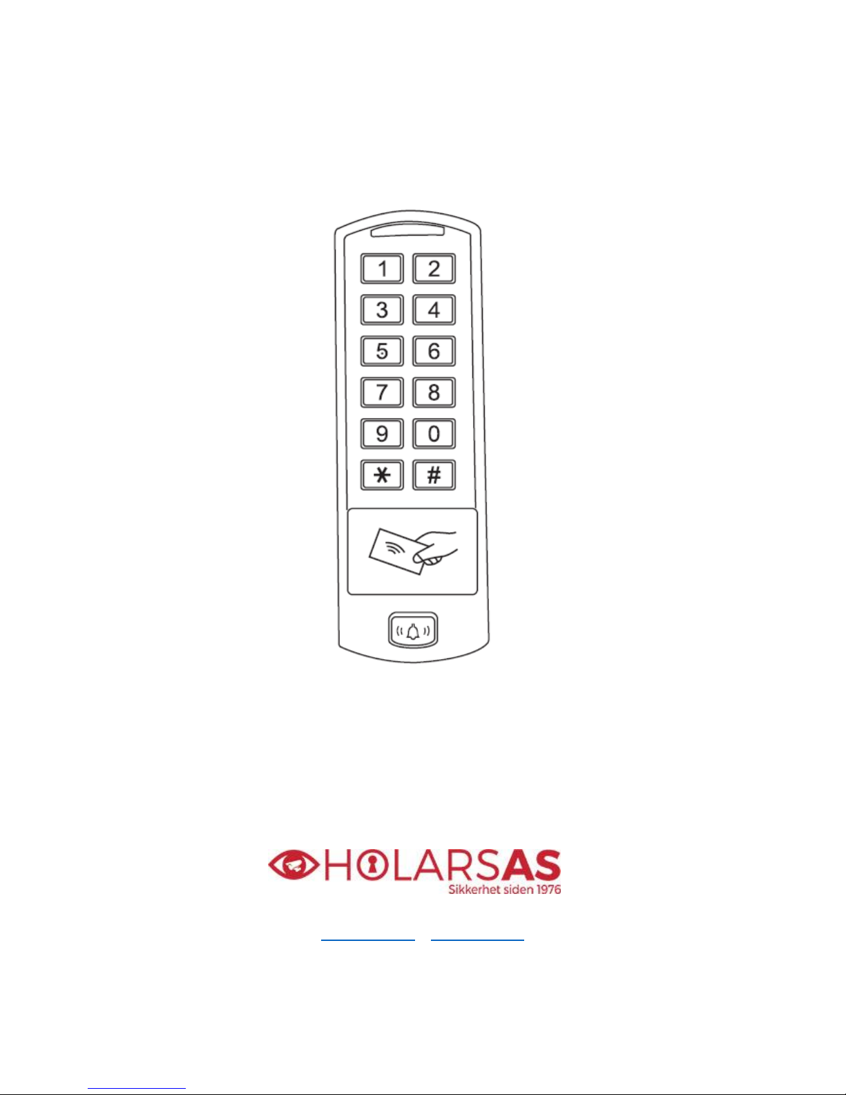
H-TAG
Access Controller / Reader
User Manual
www.holars.no – www.holars.se
Page 2

1
CONTENTS
INTRODUCTION ………………………………… 2
INSTALLATION ………………………………… 4
STANDALONE MODE ………………………… 6
CONTROLLER MODE …………………………11
WIEGAND READER MODE ………………… 13
ADVANCE APPLICATION ………………….. 14
INTRODUCTION
The H-TAG is a single door multifunction standalone access controller or a Wiegand output reader.
It uses Atmel MCU assuring stable performance. The operation is very user-friendly, and lowpower
circuit makes it long service life.
The H-TAG supports 600 users, it supports multi access modes in either card access, PIN access,
Card + PIN access, or multi cards/PINsaccess. It has extra features including block enrollment,
interlocked, Wiegand 26~37 bits interface...etc.
Features
One relay, keyboard programmer
600 users
PIN length: 4~6 digits
Card type: 125KHz EM card, 125KHz HID card, 13.56MHz Mifare card
Wiegand 26~37 bits input & output
Can be used as Wiegand reader with LED & Buzzer output
Card block enrolment
Tri-colour LED status display
Pulse mode, Toggle mode
2 devices can be interlocked for 2 doors
Built in light dependent resistor (LDR) for anti tamper
Backlit keypad
Waterproof, conforms to IP66
Low temperature resistance(-40℃)
Page 3
2
User Capacity
Common Users
Panic Users
600
598
2
Operating Voltage
Idle Current
Active Current
12~28V AC/ DC
< 65MA
< 100MA
Proximity Card Reader
Radio Technology
Read Range
Hid & EM & Mifare
125KHz &13.56Mhz
2~6 cm
Wiring Connections
Relay output, exit button, alarm, door contact,
Wiegand input, Wiegand output
Relay
Adjustable Relay Output Time
Lock Output Load
One (NO, NC, Common)
1~99 Seconds (5 seconds default)
2 Amp Maximum
Wiegand Interface
Wiegand Input
Wiegand Output
PIN Output
Wiegand 26~37bits
26~37bits
26~37bits
4 bits, 8 bits(ASCII), 10 digits Virtual Number
Environment
Operating Temperature
Operating Humidity
Meets IP66
-40 oC ~ 60 oC (-40 oF ~ 140 oF)
0%RH ~ 98%RH
Physical
Color
Dimensions
Unit Weight
Shipping Weight
Zinc-Alloy Enclosure
Powder Coat
L150×W51×H23mm
500g
650g
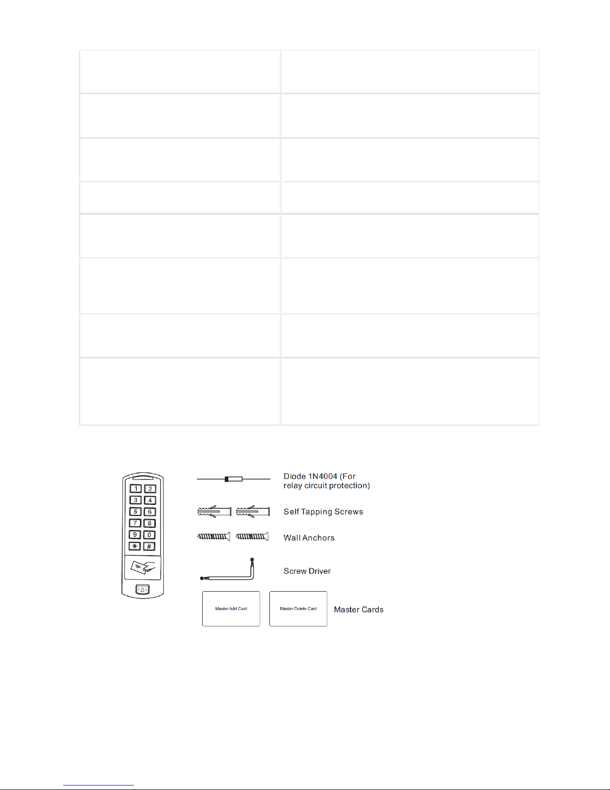
Carton Inventory
H-TAG Access Controller
Page 4
3
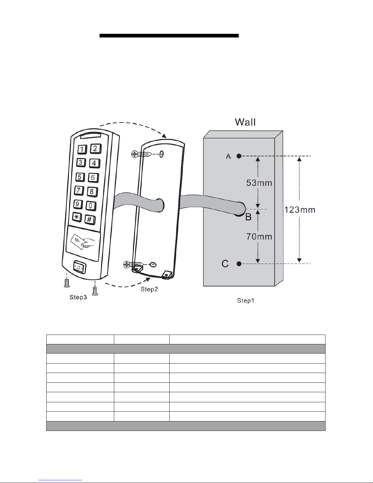
INSTALLATION
Remove the back cover from the unit
Drill 2 holes(A,C) on the wall for the screws and one hole for the cable
Knock the supplied rubber bungs to the screw holes(A,C)
Fix the back cover firmly on the wall with 4 flat head screws
Thread the cable through the cable hole(B)
Attach the unit to the back cover
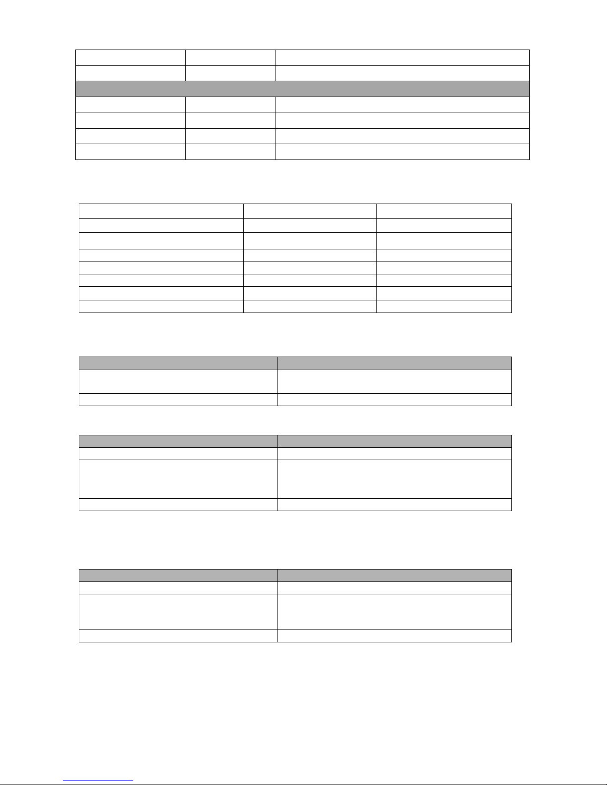
Wiring
Wire Color
Function
Notes
Basic Standalone Wiring
Red
AC & DC
12-28V AC/DC Power Input
Grey & Black
AC & DC
12-28V AC/DC Power Input
Black
GND
Negative Pole
Blue
Relay NO
Normally Open Relay Output
White & Black
Relay Common
Common Connection for Relay Output
Green & Black
Relay NC
Normally Closed Relay Output
Yellow
OPEN
Request to Exit(REX) Input
Pass-Through Wiring (Wiegand Reader or Controller)
Page 5
4
Green
Data 0
Wiegand Input/Output Data 0
White
Data 1
Wiegand Input/Output Data 1
Advanced Input and Output Features
Grey
Alarm Output
Negative contact for Alarm
Brown
Contact Input
Door/Gate Contact Input (Normally Closed)
Brown & Black
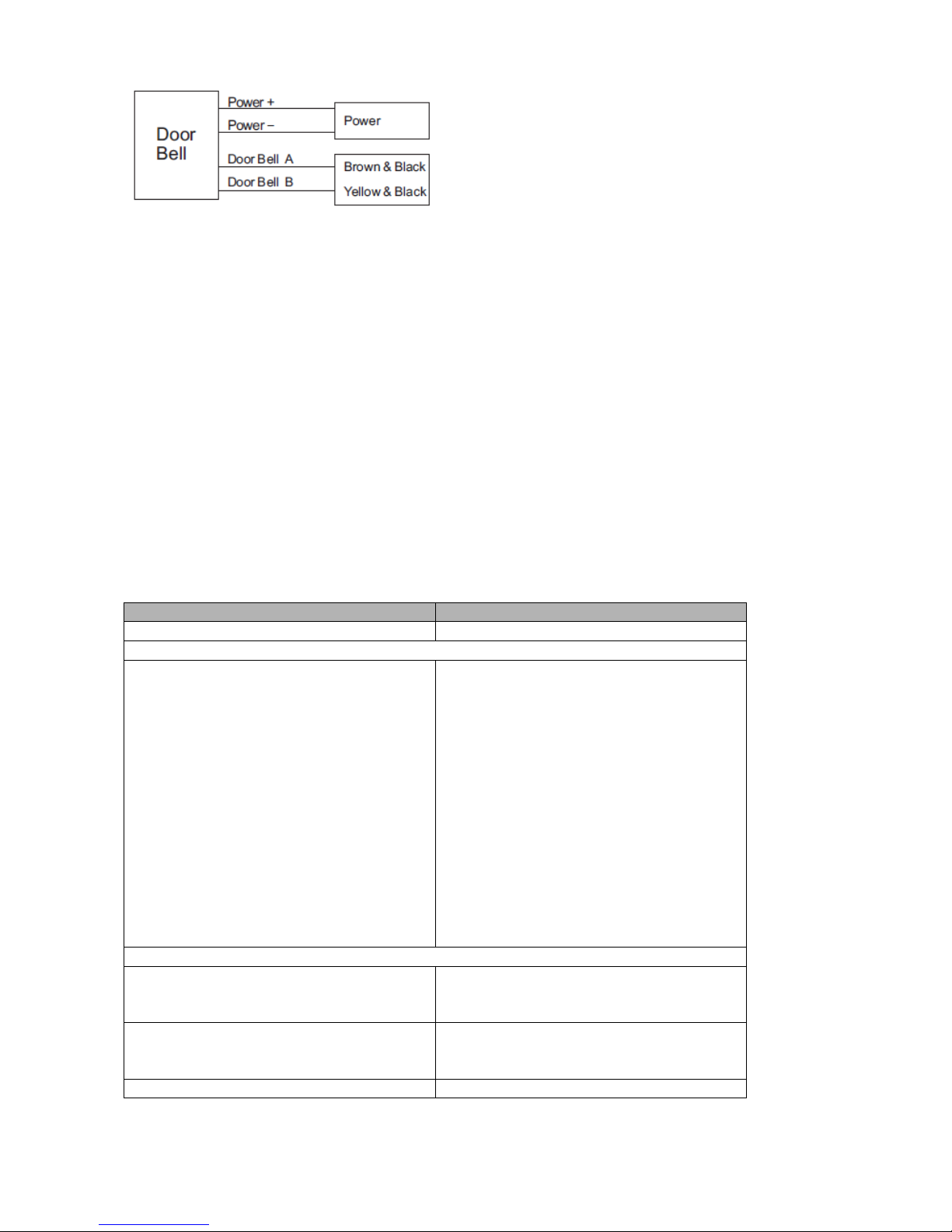
Door Bell A
Contact for Door Bell
Yellow & Black
Door Bell B
Contact for Door Bell
Sound and Light Indication
Operation Status
LED
Buzzer
Stand by
Red light bright
-
Enter into programming mode
Red light shines
One beep
In the programming mode
Orange light bright
One beep
Operation error
-
Three beeps
Exit from the programming mode
Red light bright
One beep
Open lock
Green light bright
One beep
Alarm
Red light Shines quickly
Beeps
Basic Configure
Enter and Exit Program mode
Set Master Code
Programming Step
Keystroke Combination
1. Enter Program Mode
* (Master Code) #
2. Update Master Code
0(New Master Code)#(Repeat New Master
Code)#
(Master code is any 6 digits)
3. Exit Program Mode
*
Set the Working Mode
Notes: the H-TAG has 3 working modes: Standalone Mode, Controller Mode, Wiegand Reader
Mode, choose the mode you use. (Factory default is Standalone Mode / Controller Mode)
Programming Step
Keystroke Combination
1. Enter Program Mode
* (Master Code) #
2. Standalone/Controller Mode
OR
2. Wiegand Reader Mode
8 0 # (Factory default)
8 1 #
3. Exit
*
Programming Step
Keystroke Combination
Enter Program Mode
* (Master Code) #
(Factory default is 123456)
Exit Program Mode
*
Page 6
5
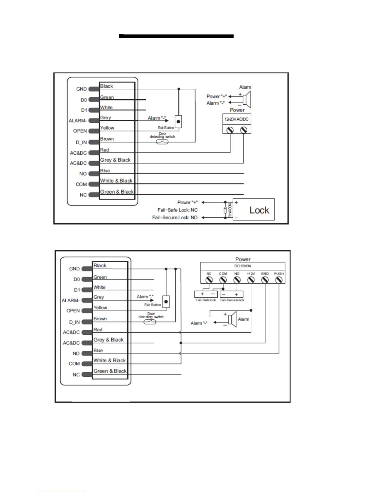
STANDALONE MODE
H-TAG can be worked as Standalone Reader for single door. (Factory default mode)---8 0 #
Connection Diagram
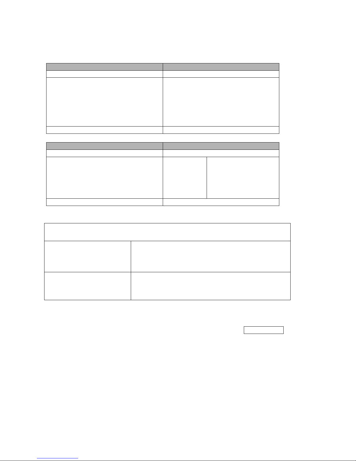
Common Power Supply:
Access Control Power Supply:
Door Bell Connect
H-TAG
H-TAG
Page 7
6
Attention:
Install a 1N4004 or equivalent diode is needed when use a common power supply, or the keypad
might be damaged.(1N4004 is included in the packing)
Programming
Programming will vary depending on access confirguration. Follow the instructions according to
your access configuration.
Notes:
User ID number: Assign a user ID to the access card / PIN in order to track it. The common
user ID number can be any number fom 0~597, the panic user ID is from 598~599.
IMPORTANT: User IDs do not have to be proceeded with any leading zeros. Recording of
User ID is critical. Modifications to the user require the User ID be available.
Proximity Card: Any 125KHz industry standard 26 bits HID and EM cards and 13.56MHz
mifare card
PIN: Can be any 4~6 digits except 8888 which is reserved.
Add Common Users
Programming Step
Keystroke Combination
1. Enter Program Mode
* (Master Code) #
Add Card User
2. Add Card: Using Auto ID
(Allows H-TAG to assign Card to next
available User ID number)
OR
2. Add Card: Select Specific ID
(Allows Master to define a specific
User ID to associate the card to)
OR
2. Add Card: by Card Number
OR
2. Add Card: Block Enrolment
(Allows Master to add up to 598 cards
to the Reader in a single step)
Takes 2 minutes to program.
1 (Read Card) #
The cards can be added continuously.
1 (User ID) # (Read Card) #
(User ID is any number from 0-597)
1 (Input 8/10 digits Card number) #
1 ( User ID) # (Card quantity) # (The
first card number) #
Cards’ number must be consecutive;
Card quantity = number of cards to be
enrolled.
Add PIN User
2. Add PIN: Using Auto ID
(Allows H-TAG to assign PIN to next
available User ID number)
1 (PIN ) #
The PINs can be added continuously.
(PIN: 4~6 digits)
2. Add PIN: Select Specific ID
(Allows manager to define a specific
User ID to associate the PIN to)
1 (User ID) # (PIN ) #
The user ID is any number from 0-597
3. Exit
*
Page 8
7
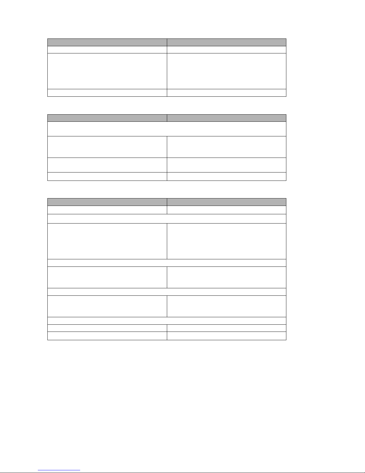
Add Panic Users
Programming Step
Keystroke Combination
1. Enter Program Mode
* (Master Code) #
2. Add Card:
OR
2. Add PIN:
1 (User ID) # (Read Card / Input 8/10
digits Card number) #
1 (User ID) # (PIN ) #
(User ID is any number from 598~599)
3. Exit
*
Change PIN Users
Programming Step
Keystroke Combination
Note: Below is done outside programming mode, users can undertake this
themselves
2. Change PIN: By Card
(There will auto allocate PIN(8888) to
cards when adding)
* (Read Card) (Old PIN) # (New PIN) #
(Repeat New PIN) #
2. Change PIN: By PIN
* (User ID) # (Old PIN) # (New PIN) #
(Repeat New PIN) #
3. Exit
﹡
Delete Users
Programming Step
Keystroke Combination
1. Enter Program Mode
﹡(Master Code) #
Delete Card User - Common
2. Delete Card - By Card
OR
2. Delete Card - By ID number
OR
2. Delete User - By Card number
2 (Read Card) #
The cards can be deleted continuously.
2 (User ID ) #
2 (Input 8/10 digits Card number) #
Delete PIN User - Common
2. Delete PIN – by PIN
OR
2. Delete PIN – By ID number
2 (Input PIN) #
2 (User ID ) #
Delete Panic User
2. Delete Panic Card User
OR
2. Delete Panic PIN User
2 (User ID ) #
2 (User ID ) #
Delete All Users
Delete All User
2 (Master Code) #
3. Exit
﹡
Page 9
8
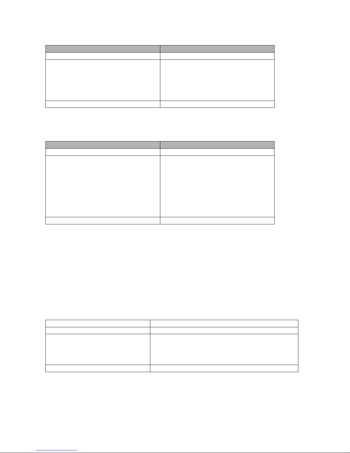
Set Relay Configuration
The relay configuration sets the behaviour of the output relay on activation.
Programming Step
Keystroke Combination
1. Enter Program Mode
* (Master Code) #
2. Pulse Mode
OR
2. Toggle Mode
3 (1-99) # (factory default)
The relay time is 1-99 seconds. (1 is
50mS.) (Default is 5 seconds)
3 0 #
Sets the relay to ON/OFF Toggle mode
3. Exit
*
Set Access Mode
For Multi cards/ PINs access mode, the interval time of reading cards/inputting PINs can not
exceed 5 seconds, or else, the H-TAG will exit to standby automatically.
Programming Step
Keystroke Combination
1. Enter Program Mode
* (Master Code) #
2. Card access
OR
2. Card + PIN access
OR
2. Card or PIN access
OR
2. Multi cards /PINs access
4 0 #
4 1 #
4 2 #
4 3 (2~9) #
(Only after reading 2~9 cards or inputting
2~9 PINs, the door can be opened)
3. Exit
*
Door Detecting
Door Open Too Long (DOTL) warning. When used with an optional magnetic contact or built-in
magnetic contact of the lock, if the door is opened normally, but not closed after 1 minute, the
inside buzzer will beep automatically to remind people to close the door and continue for 1 minute
before switching off automatically.
Door Forced Open warning. When used with an optional magnetic contact or built-in magnetic
contact of the lock, if the door is opened by force, or if the door is opened after 60 seconds of the
electro-mechanical lock not closed properly, the inside buzzer and alarm output will both operate.
Enter Master code # or valid user card /PIN to silence
Programming Step
Keystroke Combination
1. Enter Program Mode
* (Master Code) #
2. To disable door open detection
OR
2. To enable door open detection
5 0 # (factory default)
5 1 #
3. Exit
*
Page 10
9
Set Strike-out Alarm
The strike-our alarm will engage after 10 failed card attempts (Factory is OFF). It can be set to
deny access for 10 minutes after engaging or disengage only after entering a valid card/PIN or
Master code.
Programming Step
Keystroke Combination
1. Enter Program Mode
* (Master Code) #
2. Strike-Out OFF
OR
2. Strike-Out ON
OR
2. Strike-Out ON (Alarm)
6 0 # (factory default)
6 1 # Access will be denied for 10
minutes
6 2 #
3. Exit
*
Set Audible and Visual Response
Programming Step
Keystroke Combination
1. Enter Program Mode
* (Master Code) #
2. Control Sounds
OR
2. Control LED
OR
2. Control Keypad Backlit
OFF = 7 0 #
OFF = 7 2#
OFF = 7 4 #
ON = 7 1 #
ON = 7 3 #
ON = 7 5 #
(factory defaults are ON)
3. Exit
*
Master Cards Usage
Using Master Cards to add and delete card / PIN users
Add a User
1. (Read Master Add Card)
2. (Read User Card) / (Input User PIN #)
Repeat Step 2 for additional user cards / PINs
3. (Read Master Add Card)
Delete a User
1. (Read Master Delete Card)
2. (Read User Card) / (Input User PIN #)
Repeat Step 2 for additional user cards/ PINs
3. (Read Master Delete Card)
Users Operation & Reset to Factory Default
- Open the door: Read valid user card or inputting valid user PIN
- Remove Alarm: Read valid user card or inputting valid user PIN, or input Master Code #
- To reset to factory default & Add Master Cards:power off, press the exit button, hold it and
power on, there will be two beeps, and the LED light turns into yellow, release the exit button, then
read any two cards(can be 125KHz EM card, 125KHz HID card or 13.56MHz Mifare card, the LED
will turn into red, means reset to factory defaultsuccessfully. Of the two cards reading,the 1st one is
Master Add Card, the 2nd one is the Master Delete Card.
Remarks:
① If no Master Cards added, must press the Exit Button for at least
10 seconds before release.
② Reset to factory default, the user's information is still retained.
Page 11
10
CONTROLLER MODE
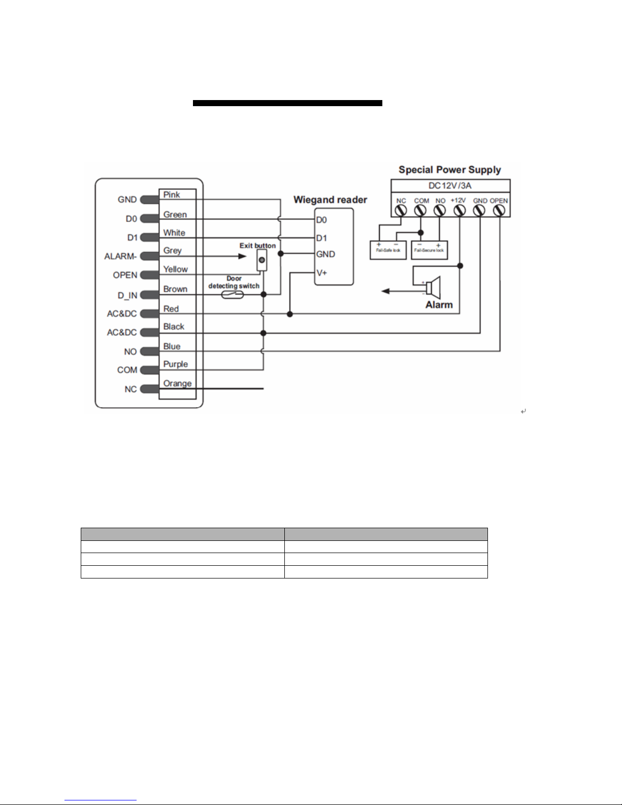
H-TAG can work as Controller, connected with the external Wiegand reader. (Factory default
mode)---8 0#
Connection Diagram
Attention: Install a 1N4004 or equivalent diode is needed when use a common power supply, or
the reader might be damaged. (1N4004 is included in the packing)
Set Wiegand Input Formats
Please set the Wiegand input formats according to the Wiegand output format of the external
Reader.
Programming Step
Keystroke Combination
1. Enter Program Mode
* (Master Code) #
2. Wiegand input bits
8 (26~37) # (factory default is 26bits)
3. Exit
*
Programming
- Basic Programming is the same as Standalone Mode
- There are some exceptions for your attention:
H-TAG Connected with Enternal Card Reader:
• If EM card reader or HID card reader: users can be added/deleted on either H-TAG or external
reader.
• If Mifare reader: users can only be added/deleted on external reader.
Page 12
11
H-TAG Connected with Fingerprint Reader:
For example:
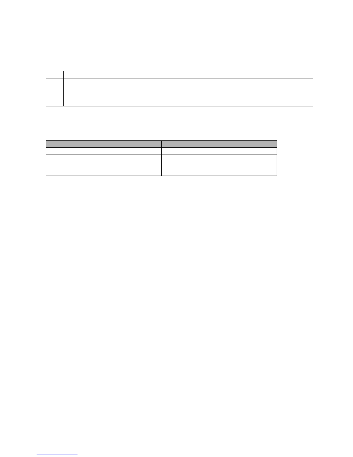
Connect F2 as the fingerprint reader to H-TAG, it is of two steps to enroll the valid fingerprint.
Step 1: Add the Fingerprint (A) on F2
Step 2: Add the same Fingerprint(A) on H-TAG:
1.
Enter Program Mode : * (Master Code) #
2.
OR
2.
1 (Press Fingerprint A once on F2) # (ID auto allocated)
1 (User ID) # (Press Fingerprint A on F2) # (Select specific ID)
3.
Exit: *
H-TAG Connected with Keypad Reader:
The keypad reader can be 4 Bits, 8 Bits (ASCII), or 10 Bits output format.
Choose the below operation according to the PIN output format of your reader.
Programming Step
Keystroke Combination
1. Enter Program Mode
* (Master Code) #
2. PIN input bits
8 (4 or 8 or 10) #
(factory default is 4bits)
3. Exit
*
Remarks: 4 means 4 bits, 8 means 8 bits, 10 means 10 digits virtual number.
• Add PIN Users:
To add PIN users, after enter into programming mode on H-TAG, PIN(s) can be input/ added on
either H-TAG controller or the external Keypad Reader.
• Delete PIN Users: the same way as add users.
Page 13
12
WIEGAND READER MODE
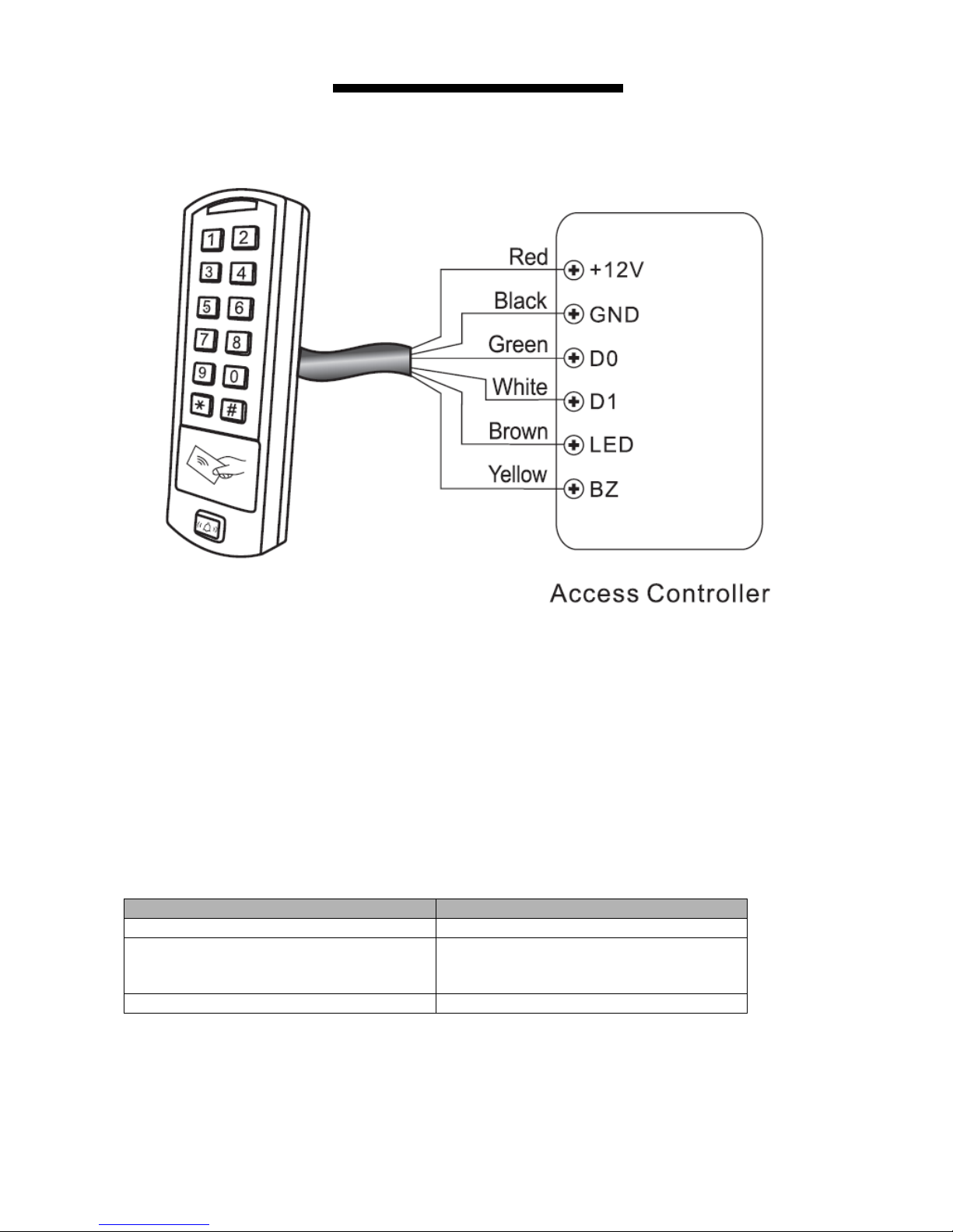
H-TAG can work as Standard Wiegand Reader, connected to the third party Controller--- 8 1 #
Connection Diagram
Notes:
• When set into Wiegand Reader mode, nearly all settings in Controller Model will become
invalid. And Brown & Yellow wires will be redefined as below:
-Brown wire: Green LED light control
-Yellow wire: Buzeer control
• If you need to connect Brown/Yellow wires:
When the input voltage for LED is low, the LED will turn into Green; and when the input
voltage for Buzzer is low, it will sound.
Set Wiegand Output Format
Please set the Wiegand output format of Reader according to the Wiegand intput format of the
Controller.
Programming Step
Keystroke Combination
1. Enter Program Mode
* (Master Code) #
2. Wiegand output bits
PIN output bits
8 (26~37) # (factory default is 26bits)
8 (4 or 8 or 10) # (Factory default is
4bits)
3. Exit
*
H-TAG
Page 14
13
ADVANCE APPLICATION
Interlock
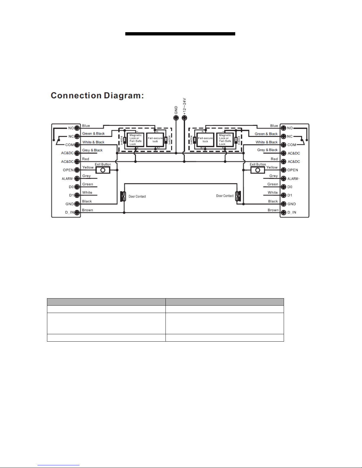
The H-TAG supports the Interlock funciton. It is of two keypads for two doors, and mainly used for
banks, prisons, and other places where a higher level security is required.
Connection Diagram:
Remarks: The Door Contact must be installed and connected as the diagram.
Let’s name the two H-TAG Keypads as “A “and “B” for two doors “1” and “2”
Step 1:
Enroll the users on Keypad A, then transfer the users’ information to Keypad B by ”User
Information Transfer” funciton.
Step 2:
Set both of the two readers (A and B) to Interlock function
Programming Step
Keystroke Combination
1. Enter Program Mode
* (Master Code) #
2. Interlocked-OFF
OR
2. Interlocked-ON
9 0 # (factory default)
9 1 #
3. Exit
*
The interlock operation is finished,
When and only door 2 is closed, the user can read the valid card or input PIN on Reader A, door 1
will open; then when and only door 1 closed, read valid card or input PIN on Reader B, door 2 will
open.
H-TAG
H-TAG
Page 15
14
H-TAG - Simplified Instruction
Function description
Operation
Enter the programming mode
*- 123456 - #
then you can do the programming
(123456 is the factory default master code)
change the master code
0 – new code - # - repeat the new code - #
(code: 6 digits)
Add card user
1- Read Card - #
(can add Cards continuously)
Add PIN user
1- PIN - #
Delete user
2 – Read Card -# for Card user
2 – PIN -# for PIN user
Exit from the programming mode
*
How to release the door
Card User
Read card
PIN User
Input PIN #
 Loading...