

Hokkaido HKEI 263 G, HKEI 353 G, HKEI 503 G, HCNI 263 G, HCNI 353 G Service Manual
...
SERVICE MANUAL
HOKKAIDO AIRCONDITIONER
DC INVERTER
SPLIT WALL-MOUNTED TYPE
HKEI-HCNI 263 XR
HKEI-HCNI 353 XR
HKEI-HCNI 503 XR

CONTENTS
Sommario
1. Precaution .............................................................................................................. 1
1.1 Safety Precaution ............................................................................................ 1
1.2 Warning ......................................................................................................... 1
2. Function ................................................................................................................. 4
3. Dimension .............................................................................................................. 6
3.1 Indoor Unit ..................................................................................................... 6
HKEI 263 XR HKEI 353 XR ............................................................... 6
3.2 Outdoor Unit ................................................................................................... 6
HCNI 263 XR ................................................................................................... 6
4. Specification ........................................................................................................... 8
5. Refrigerant cycle diagram ...................................................................................... 9
6. Wiring diagram ..................................................................................................... 10
6.1 Indoor Unit ....................................................................................................10
HKEI 263 XR HKEI 353 XR HKEI 503 XR ............................................10
6.2 Outdoor Unit ..................................................................................................11
HCNI 263 XR .........................................................................................................11
HCNI 353 XR XR ....................................................................................................12
HCNI 503 XR ................................................................................................13
7. Installation details ............................................................................................... 14
7.1 Wrench torque sheet for installation .................................................................14
7.2 Connecting the cables .....................................................................................14
7.3 Pipe length and the elevation ...........................................................................14
7.4 Air purging of the piping and indoor unit ...........................................................15
7.5 Pumping down (Re-installation) ........................................................................16
7.6 Re-air purging (Re-installation) ........................................................................17
7.7 Balance refrigerant of the 2-way, 3-way valves ..................................................18
7.8 Evacuation ....................................................................................................19
7.9 Gas charging .................................................................................................20
8. Operation characteristics ..................................................................................... 21
8.1 HKEI-HCNI 263 XR .........................................................................................21
8.2 HKEI-HCNI 353 XR .........................................................................................22
8.3 HKEI-HCNI 503 XR .........................................................................................23
9. Electronic function................................................................................................ 24
9.1 Abbreviation ..................................................................................................24
9.2 Display function .............................................................................................24
9.2.1 Icon explanation on indoor display board. ................................................24
9.2.2 LED display control function. ..................................................................24
9.3 Protection ......................................................................................................25
9.3.1 Models 263-353 XR .......................................................................................25
9.3.1.1 Three Minutes Delay at restart for compressor. ......................................25

9.3.1.2 Temperature protection of compressor top. ...........................................25
9.3.1.3 If the temperature of compressor top is too high ....................................25
9.3.1.4 Inverter module Protection ..................................................................25
9.3.1.5 Sensor protection at open circuit ..........................................................25
9.3.1.6 Fan Speed is out of control. .................................................................25
9.3.1.7 Cross Zero signal error warning. ..........................................................25
9.3.1.8 Indoor fan delayed open function .........................................................25
9.3.1.9 For all modes, when the units are turned on ..........................................25
9.3.1.10 Compressor preheating function. ........................................................25
9.3.2 Protection (Model 503 XR) ............................................................................26
9.4 Fan-Only Mode ...............................................................................................27
9.4.1 Temperature setting function is disabled ..................................................27
9.4.2 In this mode, the action of louver ...........................................................27
9.4.3 The action of auto fan in fan-only ............................................................27
Cooling Mode ........................................................................................................27
9.5.1 The After start the operation frequency ...................................................27
9.5.2 Indoor heat exchanger anti-freezing function............................................27
9.5.3 Outdoor unit current control in cooling mode ............................................28
9.5.4 Rating capacity test function ..................................................................28
9.5.5 Turbo function(press the “TURBO” button on remote controller) ..................28
9.5.7 Condenser high temperature ..................................................................29
9.6 Drying mode ..................................................................................................29
9.6.1 Indoor fan speed is fixed ......................................................................29
9.6.2 Overflow room temperature protection ...................................................29
9.6.3 Evaporator anti-freezing protection ........................................................29
9.6.4 Horizontal louver action ........................................................................29
9.7 Heating mode ................................................................................................29
9.7.1 Indoor fan action: Anti-cold-wind function. ...............................................29
9.7.2 Indoor fan speed can be set ...................................................................29
9.7.3 After start the operation frequency ........................................................30
9.7.4 Outdoor unit current control in heating mode. .........................................30
9.7.5 Indoor heat exchanger high temperature protection. .................................30
9.7.6 Defrosting mode. ..................................................................................31
9.7.7 Defrosting action. .................................................................................31
9.8 Auto mode function ........................................................................................32
9.8.1 This mode can be chosen with remote controller .......................................32
9.8.2 Indoor fan will choose auto speed of relevant mode. .................................32
9.8.3 If the machine switches mode between heating and cooling .......................32
9.8.4 If the setting temperature is modified ......................................................32
9.9 Forced operation function ................................................................................32
9.9.1 Forced cooling and auto function .............................................................32
9.9.2 When the machine is off ........................................................................32
9.9.3 In forced operation mode .......................................................................32
9.9.4 In forced cooling mode ..........................................................................32
9.9.5 The action of forced auto mode ...............................................................32

9.10 Action of 4-way valve ....................................................................................32
9.11 Two speeds outdoor fan function ....................................................................33
9.11.1 Outdoor fan starts at the same time with compressor ..............................33
9.11.2 Outdoor fan action in heating mode .......................................................33
9.11.3 Outdoor fan action in cooling & drying mode ...........................................33
9.12 Timer function ..............................................................................................33
9.12.1 Timing range is 24 hours ......................................................................33
9.12.2 Timer on. ...........................................................................................33
9.12.3 Timer off. ...........................................................................................33
9.12.4 Timer on/off. ......................................................................................33
9.12.5 Timer off/on. ......................................................................................33
9.12.6 The tolerance of timer is 1 minute per hour. ...........................................33
9.13 Sleep function mode .....................................................................................33
9.13.1 Operation time in sleep mode is 7 hours ................................................33
9.13.2 In cooling, heating or auto mode ...........................................................33
9.13.3 Operation process in sleep mode is as follow ..........................................33
9.13.4 If user uses timer on function in sleep mode ...........................................33
9.13.5 When user uses timer off function in sleep .............................................33
9.14 Auto-Restart function ....................................................................................33
9.15 Outdoor chassis heating cable (optional) .........................................................34
10. Troubleshooting ................................................................................................. 35
10.1 Indoor Unit Error Display ...............................................................................36
10.2 Diagnosis and Solution ..................................................................................37
10.2.1 E0 (EEPROM parameter error) error diagnosis and solution .......................37
10.2.2 E1 (indoor / outdoor units communication protection) error diagnosis and
solution .........................................................................................................37
10.2.3 E2 (zero-crossing signal error) diagnosis and solution ..............................38
10.2.4 E3 (indoor fan speed out of control) diagnosis and solution ......................38
10.2.5 E5 (Open or short circuit of outdoor ambient or condenser temperature sensor)
diagnosis and solution. ....................................................................................38
10.2.6 E6 (open or short circuit of indoor room or evaporator temperature sensor)
diagnosis and solution. ....................................................................................39
10.2.7 P0 (IGBT over-strong current protection) diagnosis and solution. ..............39
10.2.8 P1 (over voltage or too low voltage protection) diagnosis and solution. ......39
10.2.9 P2 (temperature protection of compressor top) diagnosis and solution. ......40
10.2.10 P4 (inverter compressor drive error) diagnosis and solution. ...................40
10.3 Key parts checking. ......................................................................................41
10.3.1. Compressor checking ..........................................................................41
10.3.2 Outdoor Fan Motor ..............................................................................41
10.3.3 Indoor Fan Motor ................................................................................41
10.3.4 Step Motor (Model: MP24GA). ...............................................................42
10.3.5 Temperature Sensors. .........................................................................43

1
1. Precaution
1.1 Safety Precaution
To prevent injury to the user or other
people and property damage, the following
instructions must be followed.
Incorrect operation due to ignoring
instruction will cause harm or damage.
Before service unit, be sure to read
this service manual at first.
1.2 Warning
Installation
Do not use a defective or underrated
circuit breaker. Use this appliance on a
dedicated circuit.
There is risk of fire or electric shock.
For electrical work, contact the
dealer, seller, a qualified electrician, or an
Authorized service center.
D o n o t d i s a s s e m b l e o r r e p a i r t h e p r o d uct, there
is risk of fire or electric shock.
Always ground the product.
There is risk of fire or electric shock.
Install the panel and the cover of
control box securely.
There is risk of fire of electric shock.
Always install a dedicated circuit and
breaker.
Improper wiring or installation may cause fore
or electric shock.
Use the correctly rated breaker of
fuse.
There is risk of fire or electric shock.
Do not modify or extend the power
cable.
There is risk of fire or electric shock.
D o n o t i n s t a l l , r e m o v e , o r r e i n s t a l l t h e
unit by yourself (customer).
T h e r e i s r i s k o f f i r e , e l e c t r i c s h o c k , e x p l o s i o n , o r
injury.
Be caution when unpacking and
installing the product.
Sharp edges could cause injury, be especially
careful of the case edges and the fins on the
condenser and evaporator.
For installation, always contact the
dealer or an Authorized service center.
T h e r e i s r i s k o f f i r e , e l e c t r i c s h o c k , e x p l o s i o n , o r
injury.
Do not install the product on a
defective installation stand.
I t m a y c a u s e i n j u r y , a c c i d e n t , o r d a m a g e t o t h e
product.
Be sur e the i nsta l l a t ion a r ea d o e s n o t
deteriorate with age.
If the base collapses, the air conditioner could
fall with it, causing property damage, product
failure, and personal injury.
D o n o t l e t t h e a i r c o n d i t i o n e r r u n f o r a
long time when the humidity is very high
and a door or a window is left open.
Moisture may condense and wet or damage
furniture.
Take care to ensure that power cable
could not be pulled out or damaged during
operation.
There is risk of fire or electric shock.
Do not place anything on the power
cable.
There is risk of fire or electric shock.
Do not plug or unplug the power
supply plug during operation.
There is risk of fire or electric shock.
Do not touch (operation) the product
with wet hands.
There is risk of fire or electric shock.
Do not place a heater or other
appliance near the power cable.
There is risk of fire and electric shock.
D o n o t a l l o w w a t e r t o r u n i n t o e l e c t r i c
parts.
It may cause fire, failure of the product, or
electric shock.
Do not store or use flammable gas or
combustible near the product.
There is risk of fire or failure of product.
Do not use the product in a tightly
closed space for a long time.
Oxygen deficiency could occur.
When flammable gas leaks, turn off
the gas and open a window for ventilation
before turn the product on.
Do not use the telephone or turn switches on or
off.
There is risk of explosion or fire.
If strange sounds, or small or smoke

2
com e s fro m prod u c t. T u r n t h e bre a k e r o f f or
disconnect the power supply cable.
There is risk of electric shock or fire.
Stop operation and close the window
in storm or hurricane. If possible, remove
the product from the window before the
hurricane arrives.
There is risk of property damage, failure of
product, or electric shock.
Do not open the inlet grill of the
product during operation. (Do not touch the
electrostatic filter, if the unit is so
equipped.)
There is risk of physical injury, electric shock,
or product failure.
When the product is soaked (flooded
or submerged), contact an Authorized
service center.
There is risk of fire or electric shock.
Be cau t i o n t h a t wa t e r c o u l d n o t ent e r
the product.
There is risk of fire, electric shock, or product
damage.
Ventilate the product from time to
t i m e w h e n o p e r a t i n g i t t o g e t h e r w i t h a s t o v e ,
etc.
There is risk of fire or electric shock.
Turn the main power off when
cleaning or maintaining the product.
There is risk of electric shock.
W h e n t h e p r o d u c t i s n o t b e u s e d f o r a
l o n g t i m e , d i s c o n n e c t t h e p o w e r s u p p l y p l u g
or turn off the breaker.
There is risk of product damage or failure, or
unintended operation.
Take care to ensure that nobody
could step on or fall onto the outdoor unit.
This could result in personal injury and product
damage.
CAUTION
Always check for gas (refrigerant)
leakage after installation or repair of
product.
Low refrigerant levels may cause failure of
product.
Install the drain hose to ensure that
water is drained away properly.
A bad connection may cause water leakage.
Keep level even when installing the
product.
To avoid vibration of water leakage.
Do not install the product where the
noise or hot air from the outdoor unit could
damage the neighborhoods.
It may cause a problem for your neighbors.
Use two or more people to lift and
transport the product.
Avoid personal injury.
Do not install the product where it
will be exposed to sea wind (salt spray)
directly.
It may cause corrosion on the product.
Corrosion, particularly on the condenser and
evaporator fins, could cause product
malfunction or inefficient operation.
Operational
Do not expose the skin directly to
cool air for long periods of time. (Do not sit
in the draft).
This could harm to your health.
Do not use the product for special
purposes, such as preserving foods, works
of art, etc. It is a consumer air conditioner,
not a precision refrigerant system.
There is risk of damage or loss of property.
Do not block the inlet or outlet of air
flow.
It may cause product failure.
Use a soft cloth to clean. Do not use
harsh detergents, solvents, etc.
There is risk of fire, electric shock, or damage
to the plastic parts of the product.
Do not touch the metal parts of the
product when removing the air filter. They
are very sharp.
There is risk of personal injury.
Do no t ste p on p r pu t anyt h i n g o n th e
product. (outdoor units)
There is risk of personal injury and failure of
product.
Always insert the filter securely.
Clean the filter every two weeks or more
often if necessary.
A dirty filter reduces the efficiency of the air
conditioner and could cause product

3
malfunction or damage.
Do not insert hands or other object
through air inlet or outlet while the product
is operated.
There are sharp and moving parts that could
cause personal injury.
Do not drink the water drained from
the product.
It is not sanitary could cause serious health
issues.
Use a firm stool or ladder when
cleaning or maintaining the product.
Be careful and avoid personal injury.
Replace the all batteries in the
remote control with new ones of the same
type. Do not mix old and mew batteries or
different types of batteries.
There is risk of fire or explosion.
Do not recharge or disassemble the
batteries. Do not dispose of batteries in a
fire.
They may burn of explode.
If the liquid from the batteries gets
onto your skin or clothes, wash it well with
clean water. Do not use the remote of the
batteries have leaked.
T h e c h e m i c a l i n b a t t e r i e s c o u l d c a u s e b u r n s o r
other health hazards
4
2. Function
When the power supply is
interrupted and then restore, the air
conditioners automatically restore
the previous function setting.
Maintain the room temperature in accordance with the setting
temperature.
The mode can be change by the room temperature.
The louver can be set at the desired position or
swing up and down automatically
The function is usually used in rainy days in
springtime or damp areas.
The fan is turn to low speed (cooling/heating).
The unit will be turn off at the seventh hour.
The unit will decide the louver direction according to
operation mode.
Turbo wind, high, med, low, breeze.
Restarting is for approx. 3 minutes..
Prevent the water being frozen on evaporator by sensing
the evaporator pipe temperature in cooling mode
Room temperature sensor.
Pipe temperature sensor.
Indoor unit
Operation by remote controller
Sensing by room temperature
Room temperature control
Anti-freezing control in cooling
Time Delay Safety control
Indoor fan speed control
Two-direction air vane
Sleep mode auto control
Independent dehumidification
Air flow Direction control
Auto mode
Temp . Compensat ion
Flexible wiring connection
Auto defrost
Anti-cold function
Self-diag. function
Auto-restart function
Timer function
Prevent the cold wind at the
beginning of unit start.

5
It protects the valves and prevents water from dripping.
The unit has 3 mins delay between continuously ON/OFF operations.
Outdoor unit
Power relay control
The hydrophilic fin can improve the heating efficiency at operation mode.
Hydrophilic aluminum fin
It is only operated in the heating operation mode except defrosting operation.
Anti-rust cabinet
Valve protection cover
4 way va lv e control
Made from electrolytic zinc steel sheet and anti-rust coated components.
Low noise air flow system
Bird tail propeller fan makes the outdoor unit run more quietly.
Discharge pipe temperature protect
Heating cable (Optional)
Driving heating at -15°C
6
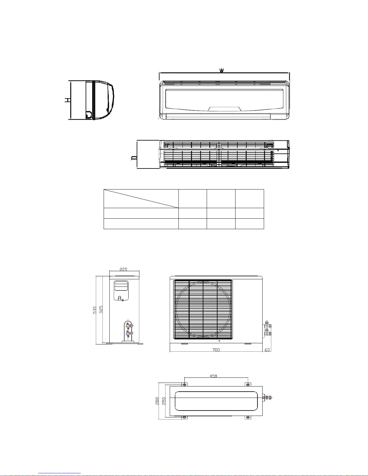
3. Dimension
3.1 Indoor Unit
HKEI 263-353-503 XR
3.2 Outdoor Unit
HCNI 263 XR
Dimension
Model
W H D
263/353
790
275
190
503
940
275
198
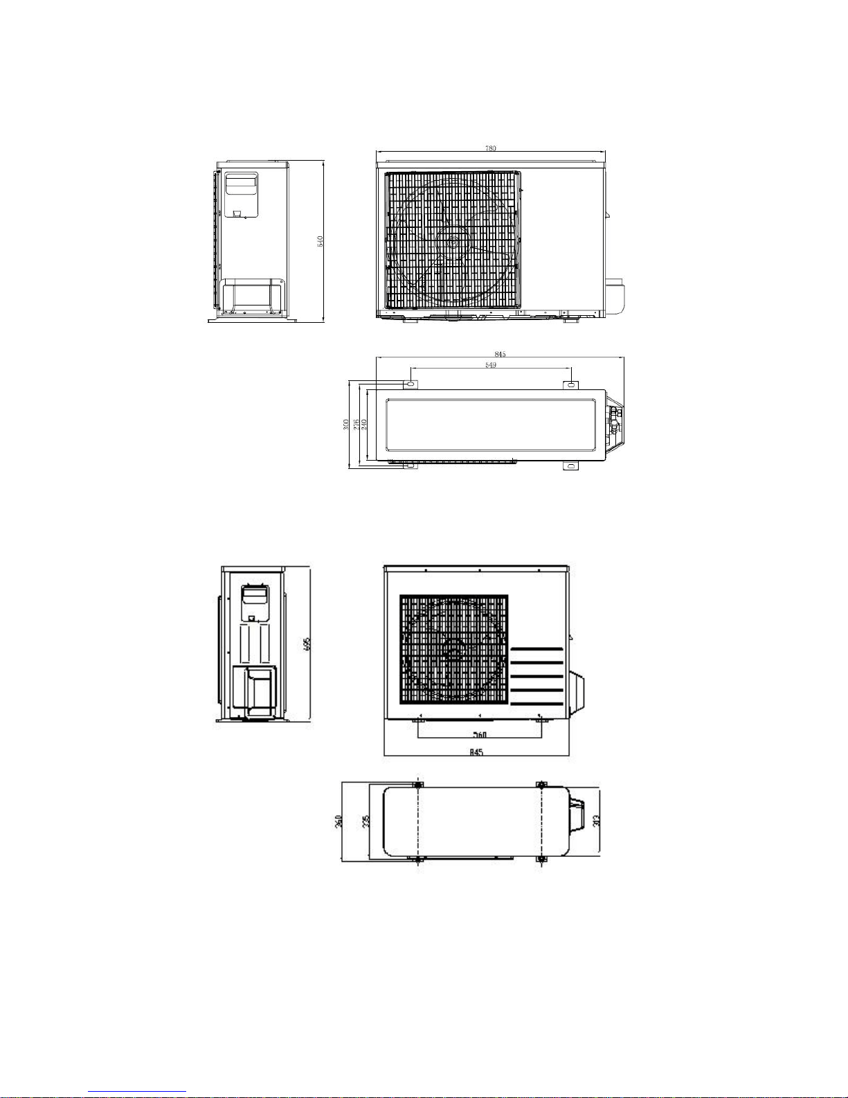
7
HCNI 353 XR
HCNI 503 XR
HCNI 503 XR
8
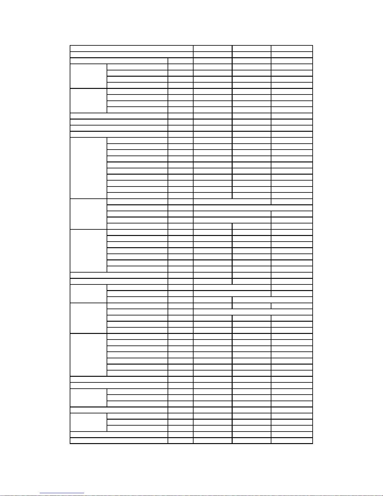
4. Specification
HKEI 263 XR HKEI 353 XR HKEI 503 XR
HCNI 263 XR HCNI 353 XR HCNI 503 XR
Ph-V-Hz 1,220-240V~,50Hz 1, 220-240V~, 50Hz 1, 220-240V~, 50Hz
Capacity KW 2,60 (0,66~2,92) 3,50 (0,71~3,94) 5,07 (2,77~5,70)
Input W 800 (180~1100) 1010 (210~1380) 1570 (730~1780)
Rated c urren t A 3.4 (0.9~4.8) 4.4 (1.0~6.2) 7,0 (3,5~7,8)
EER W/W 3,27 3,48 3,23
Capacity Btu/h 2,83 (0,67~3,21) 3,87 (0,82~4,67) 5,45 (2,34~6,13)
Input W 760 (170~1050) 1040 (210~1480) 1,47 (650~2200)
Rated c urren t A 3.2 (0.8~4.6) 4.5 (1.0~6.6) 6,7 (3,1~9,8)
COP W/W 3,74 3,72 3,71
L/h 0,90 1,10 1,80
W 1610
1750 2700
A 7,00 8,00 15,00
A 5,10
6,70 10,50
Mode l DA89X1C-23EZD1
DA89X1C-23FZ C-6RVN93H0N
Type
Rotary Rotary Rotary
Brand
Toshiba Toshiba Sanyo
Capacity Btu/h 2584
2654 4222
Input W 685
680 1010
Rated c urren t(RLA) A 4,65
4,70 6,23
Locked rotor Amp(LRA) A 10,00
10,00 13,26
Th er mal protect or CS-74
CS-74 1NT11L-3979
Capacitor uF
No No No
Refrigerant oil ml
370 370 400
Mode l
RPG25
Brand
Input W
55
Capacitor uF
1,50
Speed(hi/mi/lo) r/min 1200/1000/850 1250/1100/900 1250/1100/950
a.Number of rows 2 2 2
b.Tube pitch(a)x row pitch(b) mm 21 × 13.37 21 × 13.37 21x13.37
c.Fin spacing mm 1,3 1,3 1,3
d.Fin type (code) Hydrophilic aluminium Hydrophilic aluminium Hydrophilic aluminium
e.Tube outside dia.and type mm Ф7 innergroove tube Ф7 innergroove tube Ф7 innergroove tube
f.Coil length x height x width mm 637× 210× 26.74 637× 273× 26.74 769X232X26.74
g.Number of circuits 2 2 3
m3/h
500/420/350 550/450/350 800/700/600
dB(A)
40/34/29 41/37/31 45/42/37
Dimension (W*H*D) mm 940*275*198
Packing (W*H*D) mm 1015*350*265
Net/Gro ss weigh t Kg
7.5/9.5 8.5/10.5 11.0/13.0
Mode l
YDK24-6K YDK24-6G YDK53-6F
Brand
Input W
63/49 59/47 126/105
Capacitor uF
2,50 2,50 2,50
Spee d r/min
815/590 800/550 760/600
a.Number of rows 1 1.6
2
b.Tube pitch(a)x row pitch(b) mm 21 × 13.37 21 × 13.37
25.4x22
c.Fin spacing mm 1,4 1,4
1,6
d.Fin type (code) Hydrophilic aluminium Hydrophilic aluminium
Hydrophilic aluminium
e.Tube outside dia.and type mm Ф7 ,inn ergr oov e tu be Ф7 ,inn erg roov e t ube
Ф9.53,innergroove tube
f.Coil length x height x width mm 694x504x13.37 755x504x26.74
803×635×44
g.Number of circuits 2 2
2
m3/h 1800
2000 2500
dB(A)
53 54 58
Dimension(W*H*D) mm
700×535×235 780×540×250 845*695*335
Packing (W*H*D) mm
815×580×325 910×575×335 965*755*395
Net/Gro ss weigh t Kg
28/30 35/37 52/56
g
700 980 1700
Liquid side/ Gas side mm(inch) Ф6.35/Ф9.53 Ф6.35/Ф12.7 Ф6.35/Ф12.7
Max. refrigerant pipe length m 20 20 25
Max. difference in level m 8 8 10
℃
17 ~ 30 17 ~ 30 17 ~ 30
℃
-15 ~ 50 -15 ~ 50 -15 ~ 50
790×275×190
865×350×265
Welling
Indoor coil
Outdoor coil
RPG20E
45
1,50
Oper ati on temp
Ambient te mp
Refr igera nt typ e R41 0A
Refrigerant piping
Outdoor air flow
Outdoor noise level
Outdoor unit
Outdoor fan motor
Indoor air flow (Hi/Mi/Lo)
Indoor noise level (Hi/Mi/Lo)
Indoor unit
Indoor fan motor
Welling
Starting current
Compressor
Mois tur e Rem ova l
Max. input consumption
Max. current
Cooling
Heat ing
Indoor
Outdoor
Power supply
The above design and specifications are subject to change without prior notice for product improvement.
9
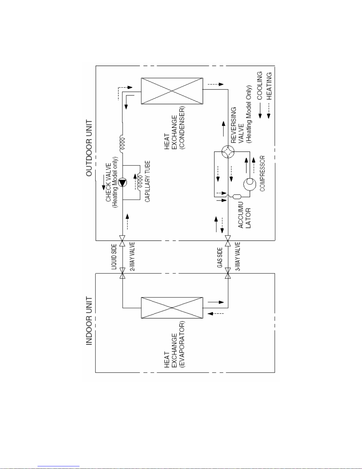
5. Refrigerant cycle diagram
10
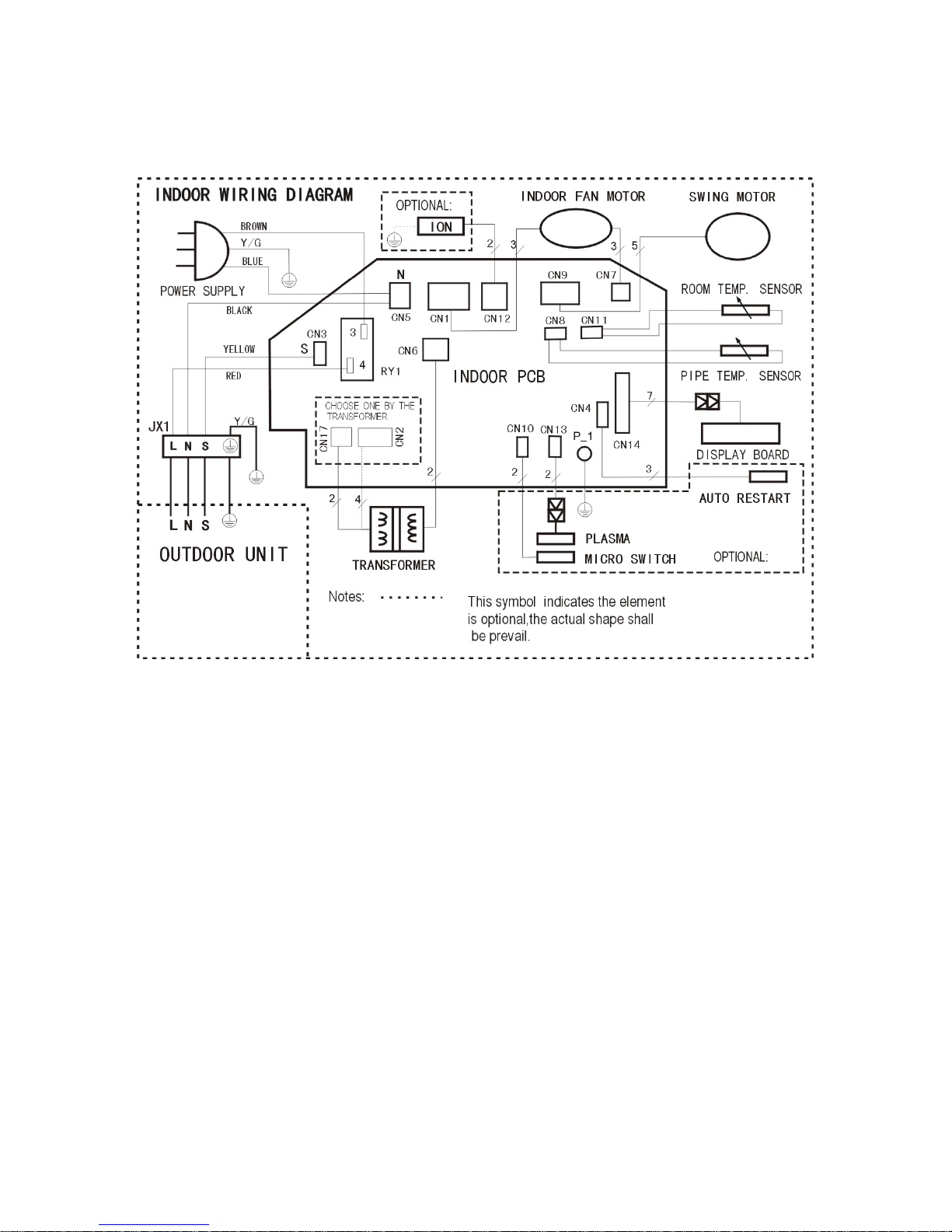
6. Wiring diagram
6.1 Indoor Unit
HKEI 263 XR HKEI 353 XR HKEI 503 XR
11
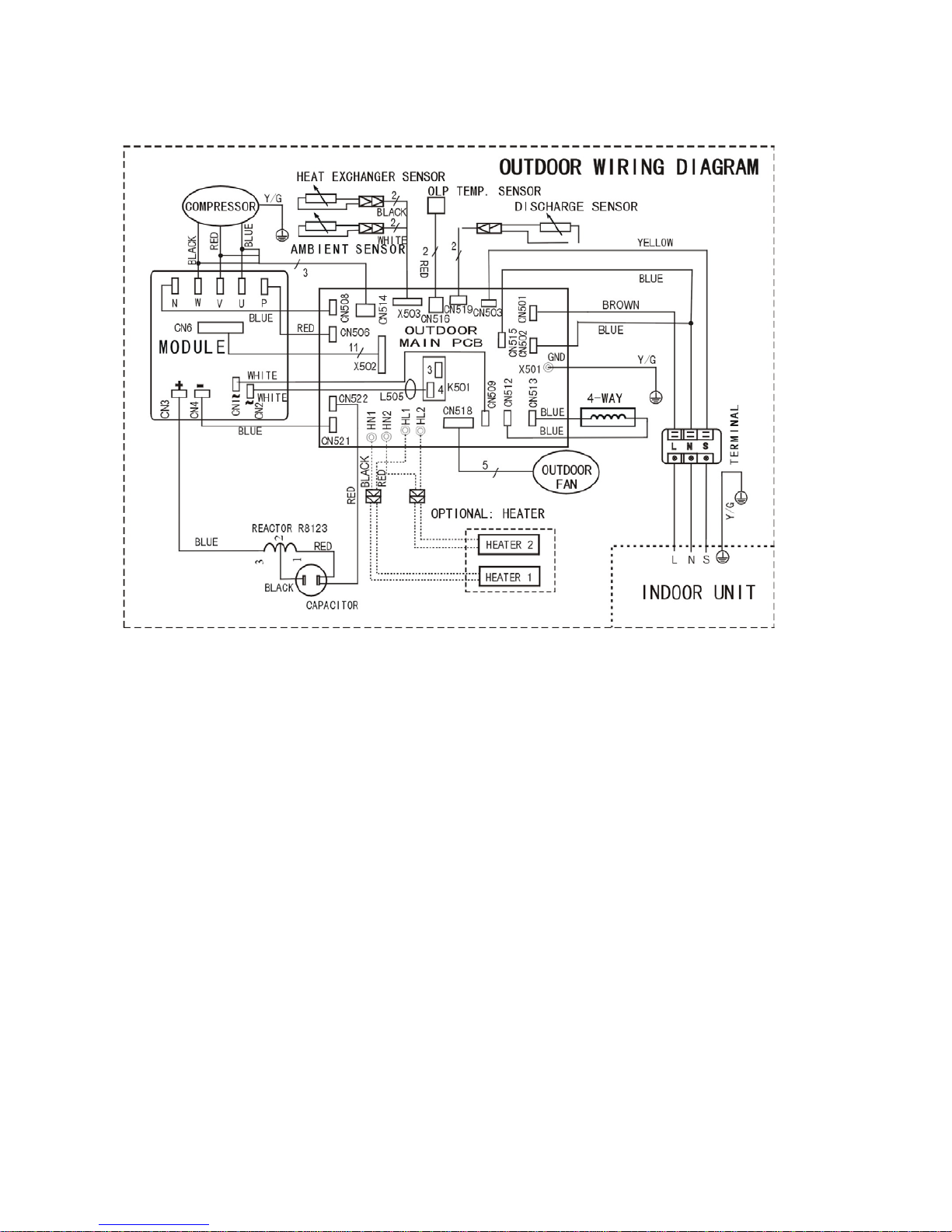
6.2 Outdoor Unit
HCNI 263 XR
 Loading...