

Hoist Fitness HF4985 User Manual
HF4985
Note: Both Serial Number and Model Number are Required when Ordering Parts
RECORD SERIAL NUMBER HERE
OWNERS MANUAL
CATALOG NUMBER
1205-000
Customer Service
(800) 548-5438
(619) 578-7676
Fa x
(619) 578-9558
ASSEMBLY
INSTRUCTIONS
CONTENTS
INSTRUCTIONS (Step 1)
FRAME ASSEMBLY (Step 2)
PRE-ASSEMBLED PARTS (Step 3)
PARTS LISTING
HARDWARE LISTING
WEIGHT TRAINING TIPS
WEIGHT TRAINING EXERCISE LOG
DECAL REFERENCE
MAINTENANCE SCHEDULE
2
4
17
21
22
23
24
25
28
Page - 1
GENERAL MAINTENANCE INFORMATION
LIMITED WARRANTY
29
31
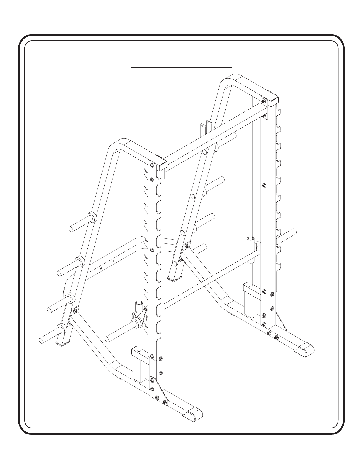
HF4985 ASSEMBLY
ASSEMBLY
INSTRUCTIONS
Step 1
INSTRUCTIONS
Before beginning assembly please take the time to read the
instructions thoroughly. Please use the catalog in this manual to
make sure that all parts have been included in your shipment.
When ordering use the part number and description from the
catalog.
to do so will void your warranty and could result in personal
injury.
effective exercise motion possible. After assembly, you should
check all functions to ensure correct operation. If you
experience problems, first recheck the assembly instructions to
locate any possible errors made during assembly. If you are
unable to correct the problem, call your authorized Hoist dealer.
Be sure to have your serial number and this catalog when calling.
When all parts have been accounted for, continue on to Step 2.
Use only Hoist replacement parts when servicing. Failure
Hoist equipment is designed to provide the smoothest, most
SUGGESTED TOOLS
Socket Wrench
3/4" Socket9/16”,
Crescent Wrench
Rubber Mallet
Tape Measure
Page - 2HF4985 ASSEMBLY

ASSEMBLY
INSTRUCTIONS
Page - 3
HF4985 ASSEMBLY
ASSEMBLY
INSTRUCTIONS
Step 2
FRAME ASSEMBLY
Page - 4HF4985 ASSEMBLY
ASSEMBLY
INSTRUCTIONS
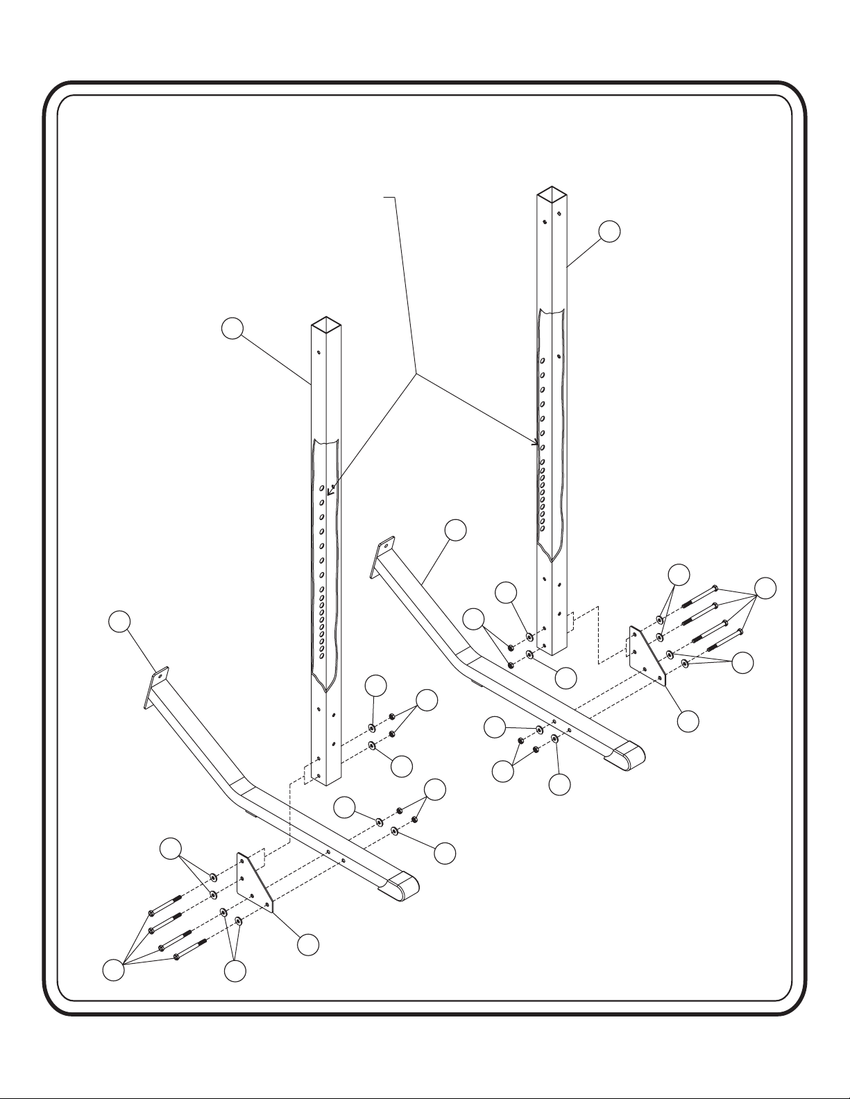
Step 2a
FRAME ASSEMBLY
Part Descriptions
1 - Right Support Beam
2 - Left Support Beam
4 - Base Support
10 - Gusset Plate
Hardware Descriptions
A - 1/2-13 UNC x 4” Hex Bolt
AA - 1/2” Flat Washer
BA - 1/2” Nylok Nut
Page - 5
HF4985 ASSEMBLY
ASSEMBLY
INSTRUCTIONS
NOTE: Parts (1) and (2) are not the same. There are
NOTE: Parts (1) and (2) are not the same. There are
on the back side of the parts that are closer to
holes on the back side of the parts that are closer to
holes
edge. That edge mounts to the inside of the unit
one
one edge. That edge mounts to the inside of the unit
shown in the diagram below). If mounted on the
(as
(as shown in the diagram below). If mounted on the
wrong
wrong side, the Safety Tier option will not work.
side, the Safety Tier option will not work.
2
1
4
AA
AA
BA
AA
BA
AA
AA
10
BA
AA
4
AA
BA
AA
AA
AA
A
AA
10
A
AA
Page - 6HF4985 ASSEMBLY
ASSEMBLY
INSTRUCTIONS
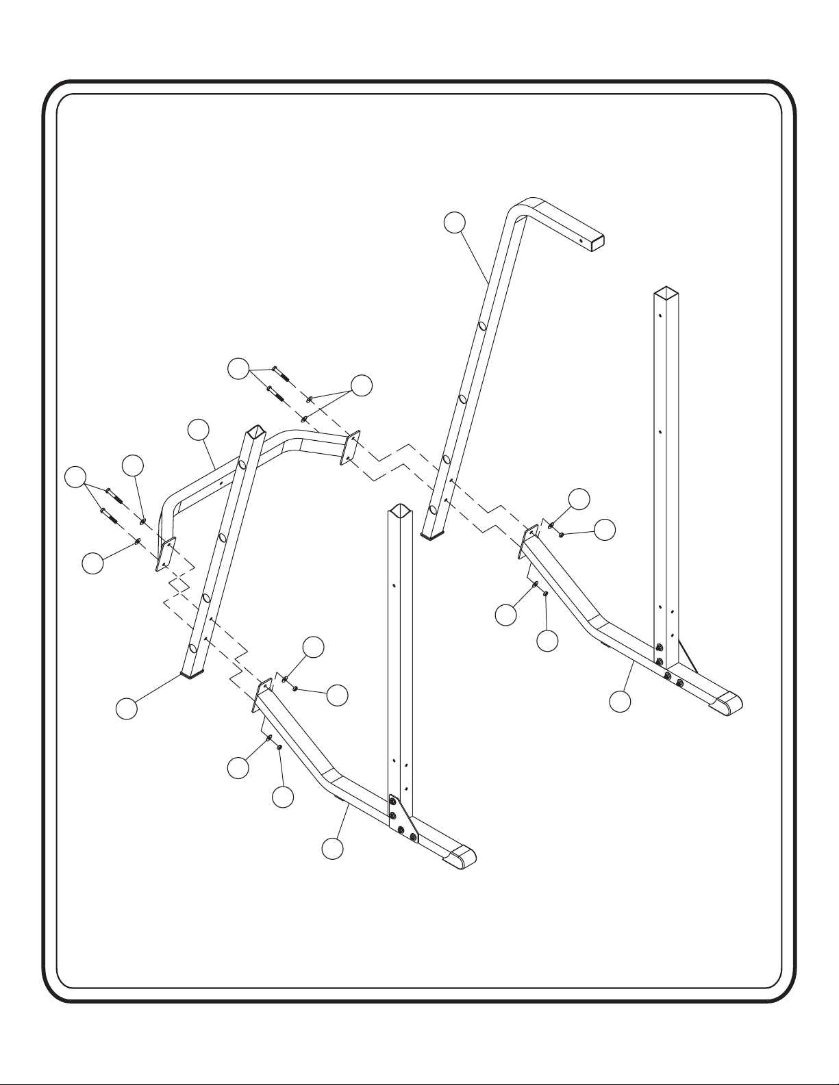
Step 2b
FRAME ASSEMBLY
Part Descriptions
4 - Base Support
5 - Rear Support
6 - Rear Cross Member
Hardware Descriptions
B - 1/2”-13UNC x 3 1/4” Hex Bolt
AA - 1/2” Flat Washer
BA- 1/2” Nylok Nut
Page - 7
HF4985 ASSEMBLY
ASSEMBLY
INSTRUCTIONS
5
B
AA
6
AA
AA
5
AA
BA
AA
BA
4
AA
BA
AA
BA
4
B
Page - 8HF4985 ASSEMBLY

ASSEMBLY
INSTRUCTIONS
Step 2c
FRAME ASSEMBLY
Part Descriptions
1 - Right Support Beam
2 - Left Support Beam
3 - Top Cross Member
5 - Rear Support
11 - Bar Rack
Hardware Descriptions
A - -13UNC x 4” Hex Bolt
1/2”
C - 1/2”-13UNC x 4 1/4” Hex Bolt
AA - 1/2” Flat Washer
BA - 1/2” Nylok Nut
Page - 9
HF4985 ASSEMBLY
 Loading...