

Hoist Fitness HF4357 Owner's Manual
HF4357
LEG PRESS HACK COMBO
Note: Both Serial Number and Model Number are Required when Ordering Parts
RECORD SERIAL NUMBER HERE
OWNERS MANUAL
CATALOG NUMBER
CATALOG NUMBER
Customer Service
(800) 548-5438
(619) 578-7676
Fa x
(619) 578-9558
1205-000

OWNERS
INSTRUCTIONS
CONTENTS
INSTRUCTIONS (Step 1) .............................................................
FRAME ASSEMBLY (Step 2) ........................................................
PRE-ASSEMBLY .....................
PARTS LISTING ............................................................................
HARDWARE LISTING ..................................................................
BOLT SIZING CHART
WASHER SIZING CHART ............................................................
DECAL PLACEMENTS .................................................................
WEIGHT TRAINING TIPS ...........................................................
..................................................................
........................................................
2
4
17
20
21
22
23
25
31
WEIGHT TRAINING EXERCISE LOG ......................................
GENERAL MAINTENANCE .........................................................
MAINTENANCE SCHEDULE........................................................
LIMITED WARRANTY ..................................................................
Page - 1
32
34
36
37
HF4357 Assembly

OWNERS
INSTRUCTIONS
Step 1
INSTRUCTIONS
Before beginning assembly please take the time to read the
instructions thoroughly. Please use the catalog in this manual to
make sure that all parts have been included in your shipment.
When ordering use the part number and description from the
catalog.
to do so will void your warranty and could result in personal
injury.
effective exercise motion possible. After assembly, you should
check all functions to ensure correct operation. If you
experience problems, first recheck the assembly instructions to
locate any possible errors made during assembly. If you are
unable to correct the problem, call your authorized Hoist dealer.
Be sure to have your serial number and this catalog when calling.
When all parts have been accounted for, continue on to Step 2.
Use only Hoist replacement parts when servicing. Failure
Hoist equipment is designed to provide the smoothest, most
SUGGESTED TOOLS
Socket Wrench
1/2”, 9/16” & 3/4” Sockets
Crescent Wrench
Rubber Mallet
Tape Measure
Page - 2HF4357 Assembly

OWNERS
INSTRUCTIONS
Page - 3
HF4357 Assembly
OWNERS
INSTRUCTIONS
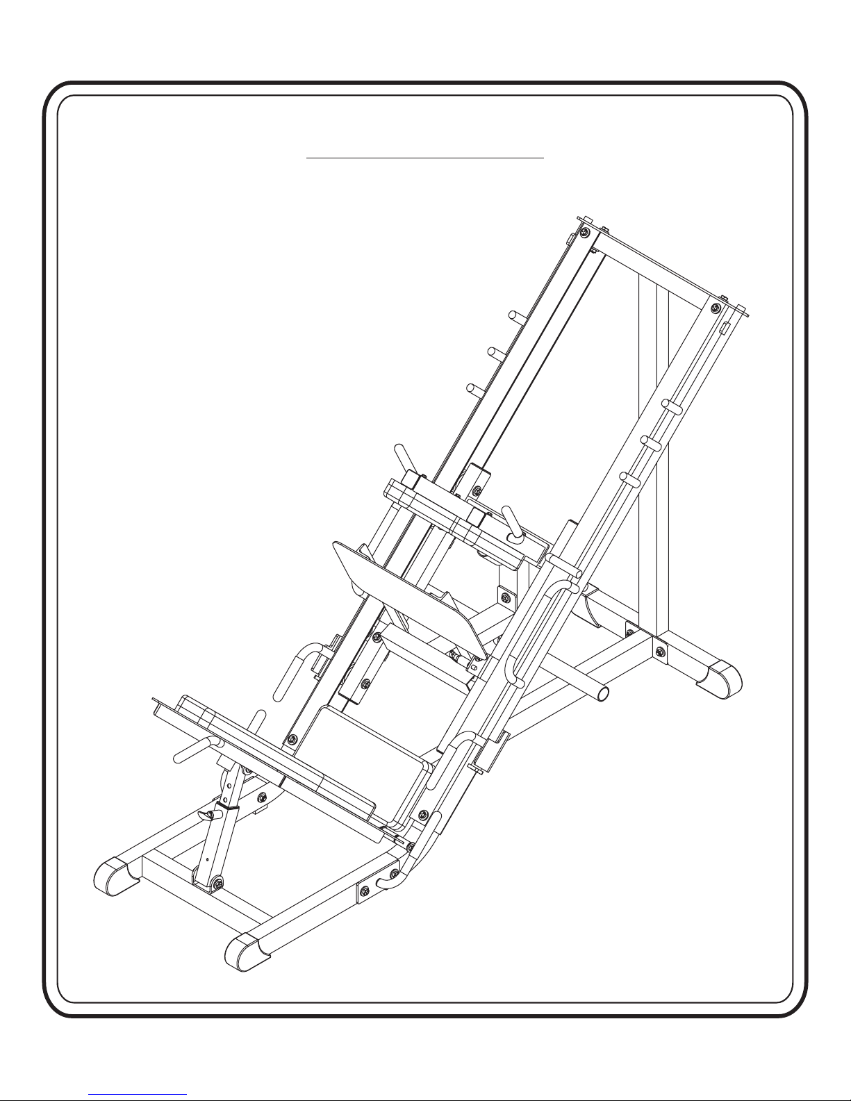
Step 2
FRAME ASSEMBLY
Page - 4HF4357 Assembly

OWNERS
INSTRUCTIONS
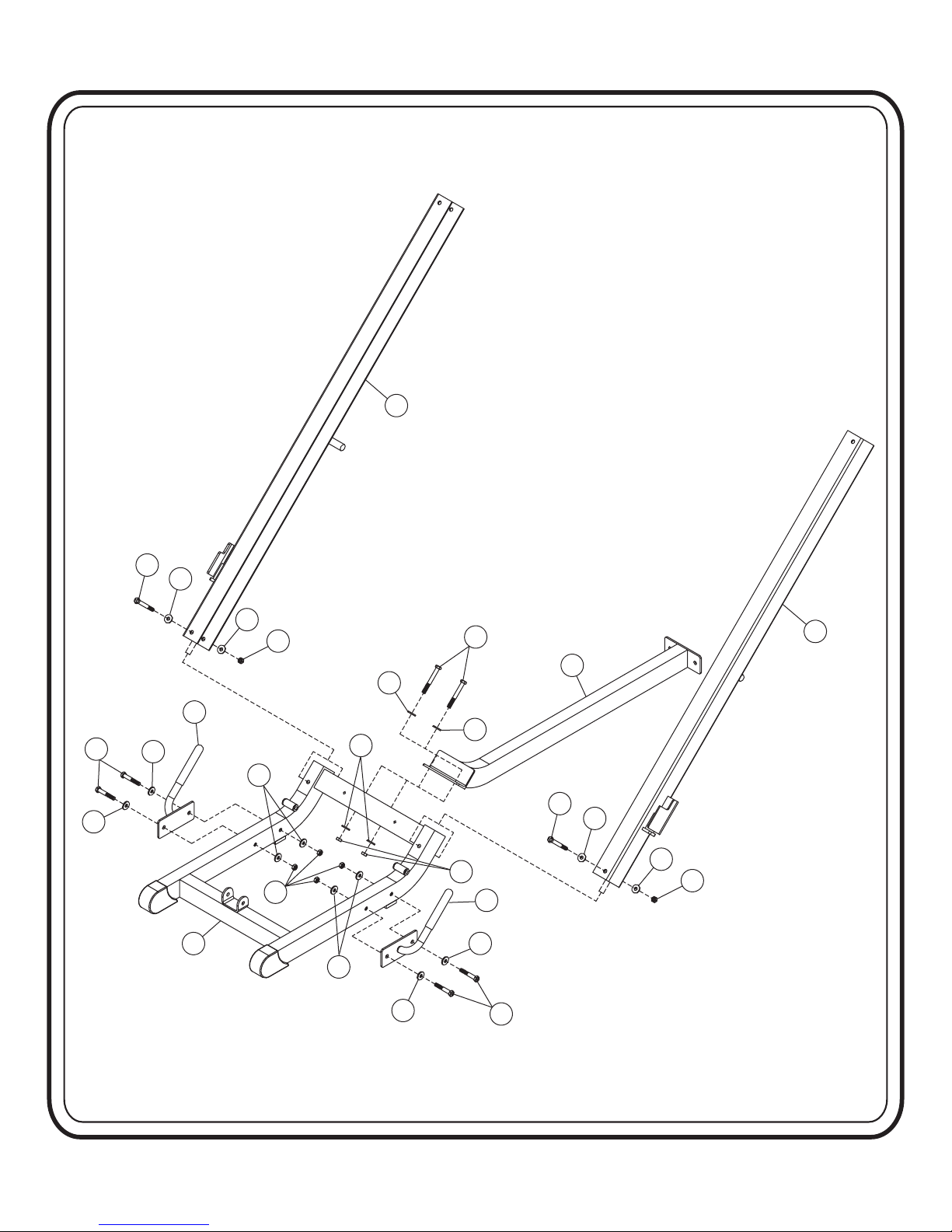
Step 2a
FRAME ASSEMBLY
Start this assembly by attaching (2) to (1). Then you will attach (4)
and (5) to (1). Finish by attaching (8)
Just Snug these bolts at this point.
and (9) to (1). .Wrench Tighten these bolts
Part Descriptions
1 - Base Front
2 - Base Runner
4 - Left Rail
5 - Right Rail
8 - Right Handle
Hardware Descriptions
A - 1/2”-13 x 3” Hex Head Screw
B - 1/2”-13 x 4” Hex Head Screw
E - 1/2”-13 x 4 1/4” Hex Head Screw
AA - 1/2” Flat Washer
BA - 1/2” Nylok Nut
9 - Left Handle
Page - 5
HF4357 Assembly
OWNERS
INSTRUCTIONS
4
AA
E
AA
AA
BA
B
2
AA
E
AA
AA
BA
8
AA
A
BA
AA
9
A
AA
AA
BA
1
AA
AA
AA
5
Page - 6HF4357 Assembly

OWNERS
INSTRUCTIONS
Step 2b
FRAME ASSEMBLY
In this step you will attach (15) to (1). Now insert (18) into (10).
Then attach (10) to (1) and (18) to (15). Wrench Tighten bolts. Then
back off 1/2” turn or enough so these parts can adjust easily.
Part Descriptions
1 - Base Front
10 - Outer Footrest Adjuster
15 - Hack Footrest
18 - Inner Footrest Adjuster
Hardware Descriptions
B - 1/2”-13 x 4” Hex Head Screw
G - 1/2”-13 x 5 1/2” Hex Head Screw
AA - 1/2” Flat Washer
BA - 1/2” Nylok Nut
Page - 7
HF4357 Assembly
OWNERS
INSTRUCTIONS
15
AA
B
AA
AA
BA
BA
BA
AA
AA
18
G
10
B
AA
G
1
BA
AA
Page - 8HF4357 Assembly

OWNERS
INSTRUCTIONS
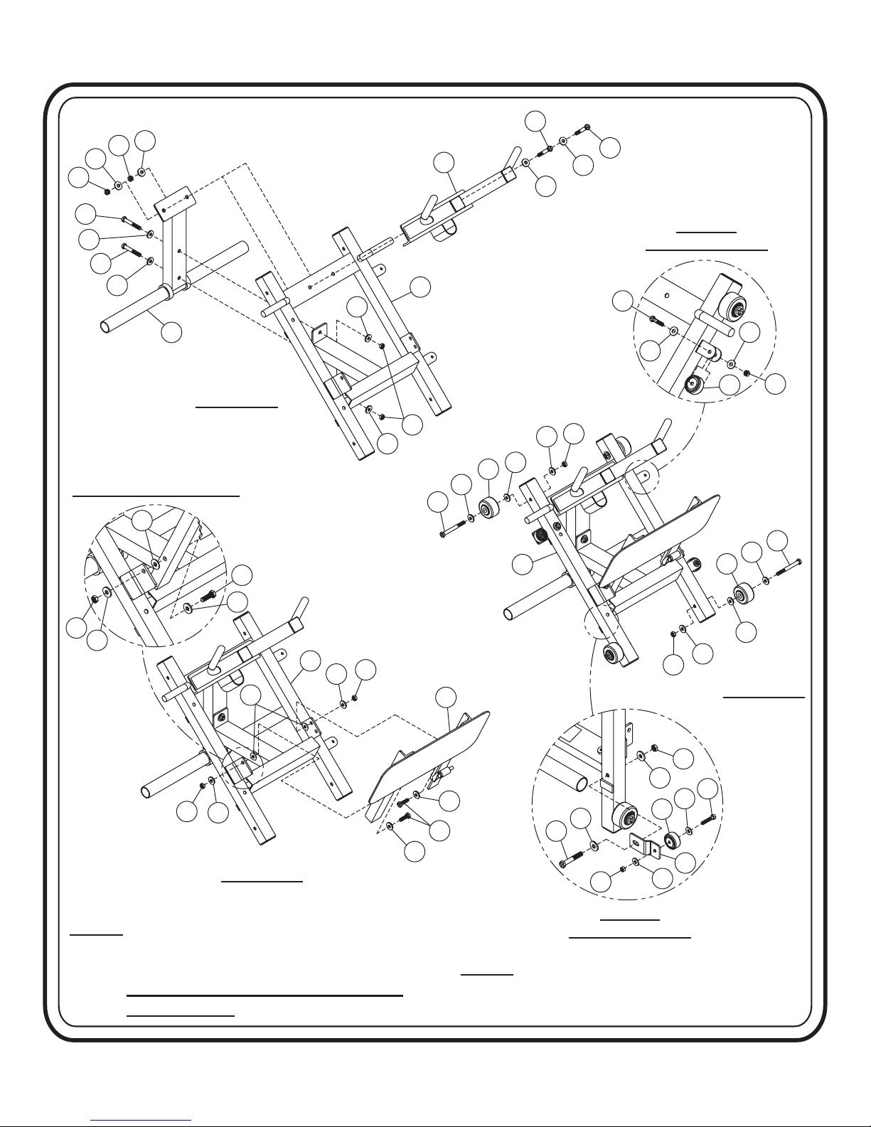
Step 2c
FRAME ASSEMBLY
Start by attaching (14) and (7) to (6). . Attach
(16) to (6).
these parts can adjust easily
Wrench Tighten bolts. Then back off 1/2” turn or enough so
. Attach (CK) to the both sides of (6). And a
(CJ) in each bracket on the right side of (6). .
Detail -A-)
(See Detail -B-)
. Attach two (CJ)’s to the two (11)’s. .
. Then attach both (11)’s to the left side of (6). Note that
Wrench Tighten bolts
Wrench Tighten bolts
Wrench Tighten bolts
(See
there is a slotted hole in (11) at this connection point which allows for
adjustment of these wheels. At this point, position the (11)’s all the way
in. . They will be adjusted out in Step 2e.
Just Snug bolts
Part Descriptions
Hardware Descriptions
6 - Carriage
7 - Shoulder Pad Mount
11 - Wheel Mount
14 - Weight Carriage
16 - Leg Press Footrest
A - 1/2”-13 x 3” Hex Head Screw
C - 1/2”-13 x 3 1/4” Hex Head Screw
D - 1/2”-13 x 1 1/2” Hex Head Screw
F - 1/2”-13 x 4 1/2” Hex Head Screw
H - 3/8”-16 x2” Hex Head Screw
AA - 1/2” Flat Washer
AB - 3/8” Flat Washer
AD - 1/2” Nylon Flat Washer
BA - 1/2” Nylok Nut
BB - 3/8” Nylok Nut
BC - 1/2” Nylok Nut
CJ - 2” Dia. Wheel
CK - 3” Dia. Wheel
(Thin)
Page - 9
HF4357 Assembly
BA
AA
BA
AA
OWNERS
INSTRUCTIONS
C
7
AA
AA
C
A
AA
A
AA
14
ASSEMBLY -1-ASSEMBLY -1-
AREA ENLARGED FOR CLARITYAREA ENLARGED FOR CLARITY
AD
AA
DETAIL -A-DETAIL -A-
ROTATED FOR CLARITYROTATED FOR CLARITY
6
AA
BA
AA
AA
CK
AA
F
D
6
AA
BC
H
AB
AB
AA
BB
F
CJ
CK
BA
AA
NOTE:
NOTE:
6
AD
BA
AA
ASSEMBLY -2-ASSEMBLY -2-
Make sure to place Nylon Washer (AD)
Make
between the Leg Press Footrest (16) and
between
Carriage (6) when assembling.
Carriage
Nylon Washer is placed in this area to
Nylon
reduce friction
reduce
sure to place Nylon Washer (AD)
the Leg Press Footrest (16) and
(6) when assembling.
Washer is placed in this area to
friction
.
.
AA
BA
AA
AA
BC
16
BA
AA
AA
AA
D
NOTE: Wheel assemblies are only shown once
NOTE: Wheel assemblies are only shown once
A
BB
DETAIL -B-DETAIL -B-
ROTATED FOR CLARITYROTATED FOR CLARITY
for clarity. Repeat assembly where
for
clarity. Repeat assembly where
applicable.
applicable.
CJ
AB
AB
11
ASSEMBLY -3-ASSEMBLY -3-
J
AA
Page - 10HF4357 Assembly

OWNERS
INSTRUCTIONS
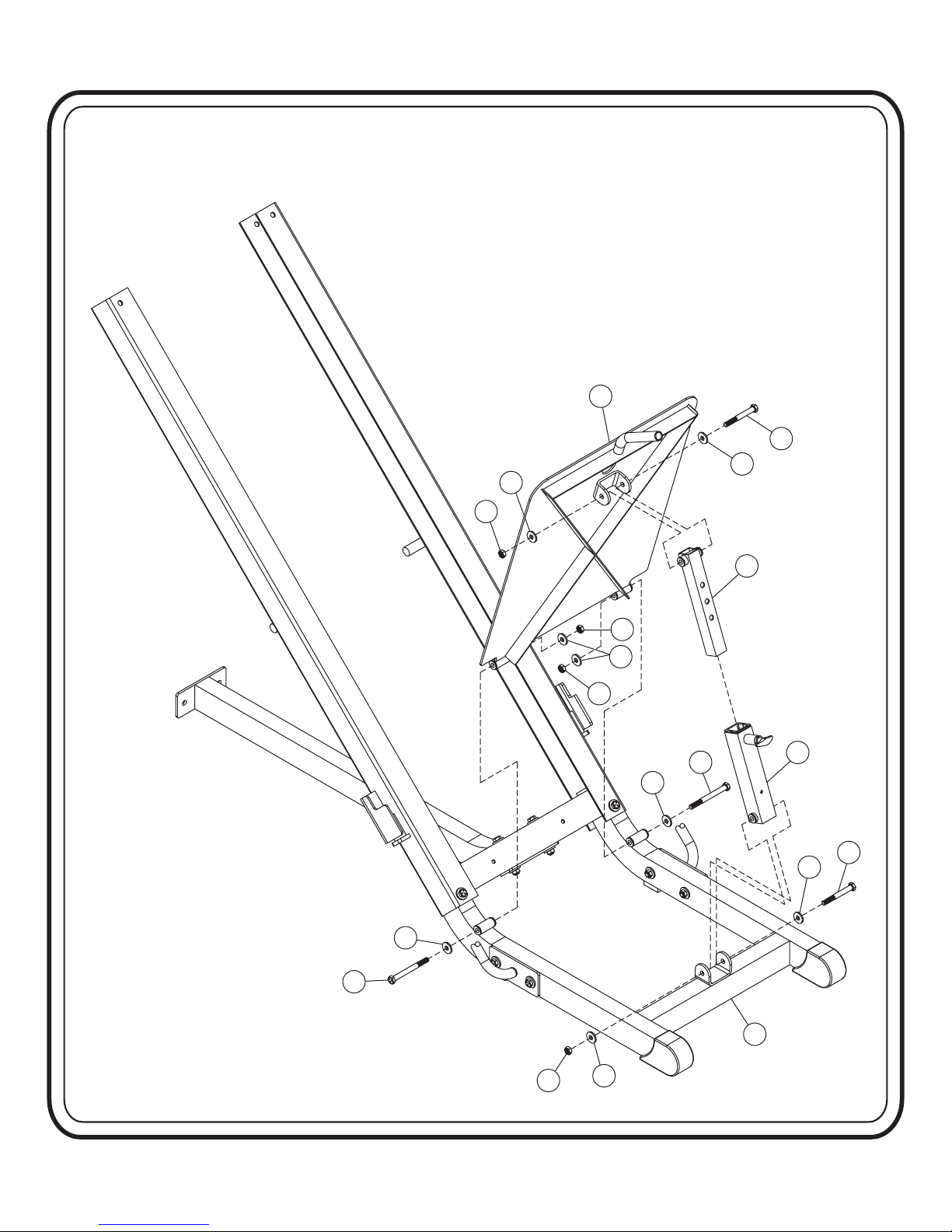
Step 2d
FRAME ASSEMBLY
Start this assembly by sliding (6) into (4) and (5). Then attach (3) to
both (4), (5) and (2). Wrench Tighten these bolts and the bolts that were
Snug Tightened in Step 2a.
Part Descriptions
2 - Base Runner
3 - Rear Upright
4 - Left Rail
5 - Right Rail
6 - Carriage
Hardware Descriptions
A - 1/2”-13 x 3” Hex Head Screw
E - 1/2”-13 x 4 1/4” Hex Head Screw
AA - 1/2” Flat Washer
BA - 1/2” Nylok Nut
Page - 11
HF4357 Assembly
 Loading...