

Hoist Fitness HD1700 User Manual
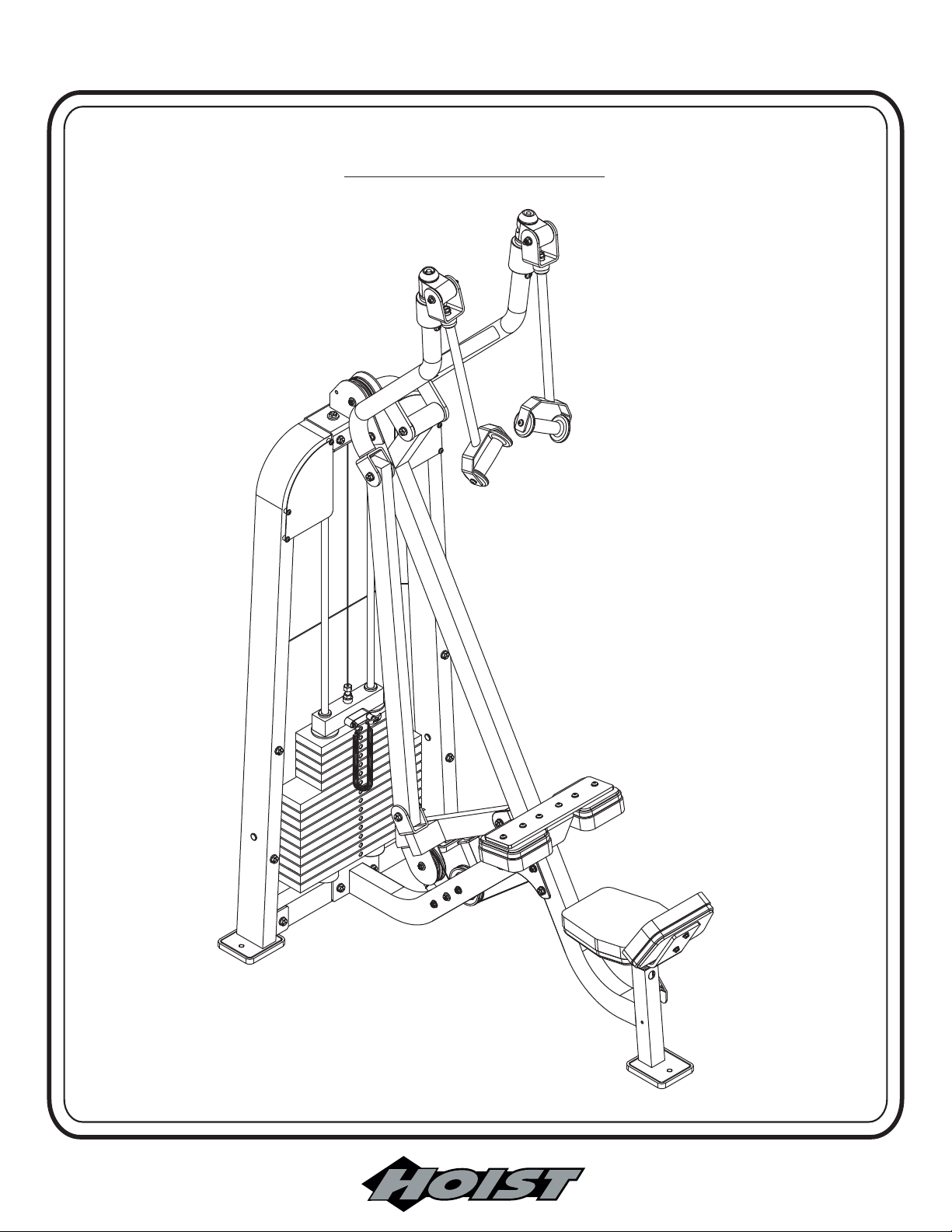
HD1700
LAT/HIGH ROW
Note: Both Serial Number and Model Number are Required when Ordering Parts
RECORD SERIAL NUMBER HERE
OWNERS MANUAL
CATALOG NUMBER
Customer Service
(800) 548-5438
(858) 578-7676
Fa x
(858) 578-9558
0102-003

OWNERS
MANUAL
CONTENTS
INSTRUCTIONS (Step 1).............................................................
FRAME ASSEMBLY (Step 2)........................................................
CABLE ASSEMBLY (Step 3).........................................................
CABLE ADJUSTMENT/GENERAL MAINTENANCE ...............
PRE-ASSEMBLED PARTS ...........................................................
PARTS LISTING ..........................................................................
HARDWARE LISTING ................................................................
BOLT SIZING CHART ................................................................
WASHER SIZING CHART ..........................................................
2
4
17
18
23
25
26
28
29
WEIGHT RATIOS .......................................................................
DECAL PLACEMENT
WEIGHT TRAINING TIPS
WEIGHT TRAINING EXERCISE LOG ...................................
GENERAL MAINTENANCE INFORMATION ..........................
MAINTENANCE SCHEDULE........................................................
LIMITED WARRANTY ................................................................
.................................................................
........................................................
31
33
39
40
42
44
45
Page - 1
HD1700 Assembly

OWNERS
MANUAL
Step 1
INSTRUCTIONS
Before beginning assembly please take the time to read the
instructions thoroughly. Please use the various lists in this
manual to make sure that all parts have been included in your
shipment.
from the lists.
Failure to do so will void your warranty and could result in
personal injury.
Hoist equipment is designed to provide the smoothest, most
effective exercise motion possible. After assembly, you should
check all functions to ensure correct operation. If you
experience problems, first recheck the assembly instructions to
locate any possible errors made during assembly. If you are
unable to correct the problem, call your authorized Hoist dealer.
Be sure to have your serial number and this manual when
calling. When all parts have been accounted for, continue on .
When ordering use the part number and description
Use only Hoist replacement parts when servicing.
TOOLS REQUIRED
Socket Wrench
1/2”, 9/16" and 3/4" Sockets
3/4” Open End Wrench
Crescent Wrench
Rubber Mallet
Tape Measure
Page - 2HD1700 Assembly

OWNERS
MANUAL
Page - 3
HD1700 Assembly
OWNERS
MANUAL
Step 2
FRAME ASSEMBLY
Page - 4HD1700 Assembly

OWNERS
MANUAL
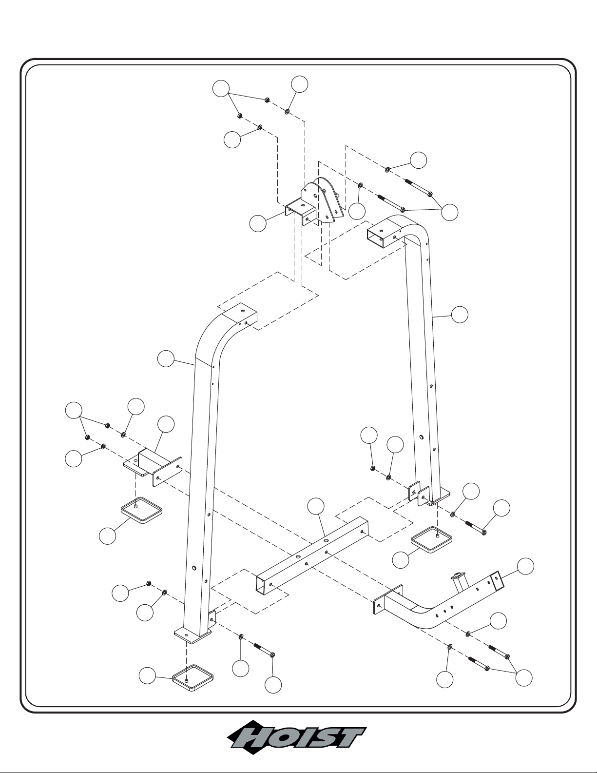
Step 2a
FRAME ASSEMBLY
Start assembly by attaching both (1)’s to (3). Attach (2) to the top of
both (1)’s. Then attach (4) and (5) to (3). bolts. They will
be tighten in a later step.
Part Descriptions
1 - Weight Frame Upright
2 - Top Pulley Mount
3 - Weight Stack Mount
4 - Rear Tie
5 - Front Support
Hardware Descriptions
A - 1/2”-13UNC x 4 3/4” Hex Head Bolt (WZ)
B - 1/2”-13UNC x 3” Hex Head Bolt (WZ)
AA - 1/2” Washer
BA - 1/2” Nylok Nut
Hand Tighten
Page - 5
HD1700 Assembly
OWNERS
MANUAL
BA
AA
2
1
AA
AA
AA
A
1
BA
AA
CA
BA
AA
AA
CA
4
BA
AA
AA
AA
3
CA
B
AA
B
5
AA
B
Page - 6HD1700 Assembly

OWNERS
MANUAL
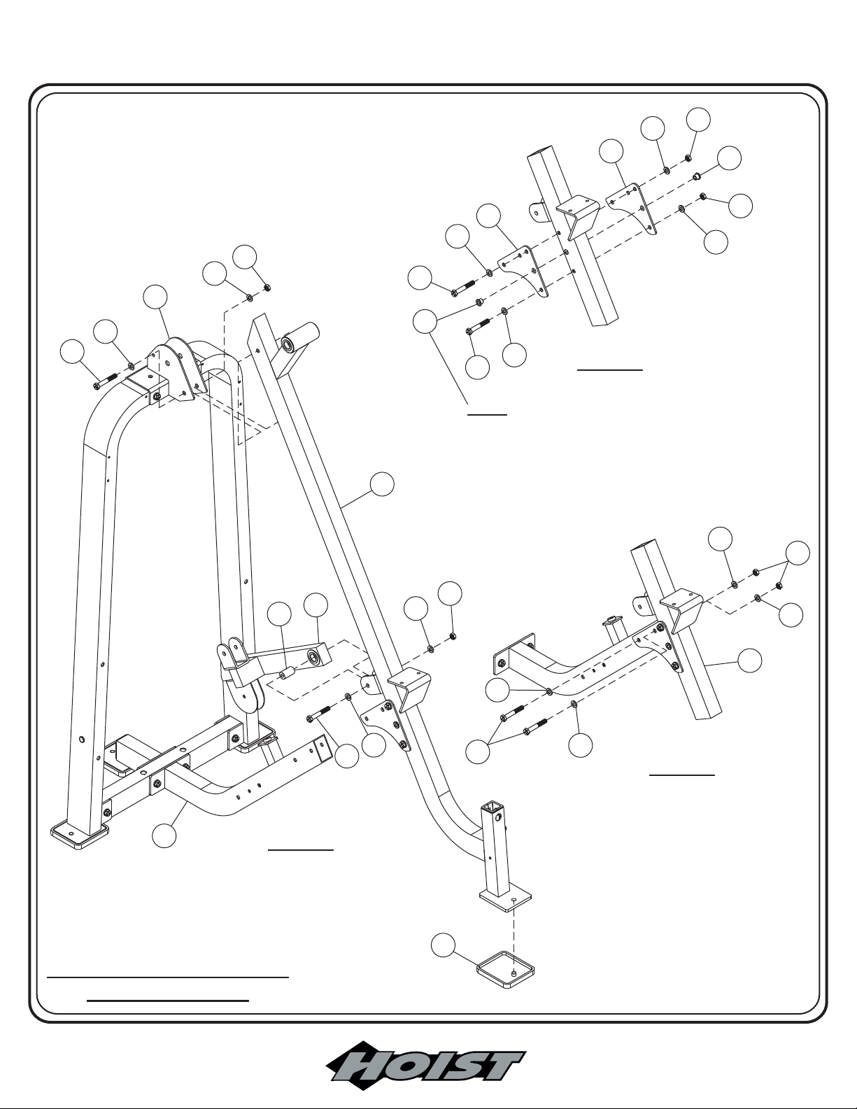
Step 2b
FRAME ASSEMBLY
Continue assembly by attaching both (7)’s to (6); when
NOTE:
securing both (7)’s, and (5) together, slide (CT) into the holes on (7) and
(6) before securing with (B) to ensure proper alignment. (CT) acts as a
spacer for a pulley which is installed in a later step.. Attach (6) to (2) and
(5). Then insert (CS) into (8) and attach (8) to (6). all
bolts. If the Resistance Lever Arm (8) does not swing freely.
NOTE:
Wrench Tighten
Turn back the nut (BA) till the arm swings freely.
Part Descriptions
2 - Top Pulley Mount
5 - Front Support
6 - Front Upright
7 - Gusset Plate
Hardware Descriptions
B - 1/2”-13UNC x 3” Hex Head Bolt (WZ)
C - 1/2”-13UNC x 3 1/4” Hex Head Bolt (WZ)
AA - 1/2” Washer
BA - 1/2” Nylok Nut
CA - Rubber Foot Pad
CS - 19mm dia. x 57.5mm lg. Axle
CT - 11/16” Flanged Spacer
Page - 7
HD1700 Assembly
OWNERS
MANUAL
AA
7
7
AA
BA
AA
2
AA
B
B
CT
AA
B
NOTE: WHEN SECURING BOTH (7)’S, (6),
NOTE: WHEN SECURING BOTH (7)’S, (6),
(5) TOGETHER, SLIDE (CT) INTO HOLES
AND (5) TOGETHER, SLIDE (CT) INTO HOLES
AND
(7) AND (6) BEFORE SECURING WITH (B) TO
ON
ON (7) AND (6) BEFORE SECURING WITH (B) TO
ENSURE
ENSURE PROPER ALIGNMENT. (CT) ACTS AS A
SPACER
6
SPACER FOR A PULLEY WHICH IS INSTALLED IN
PROPER ALIGNMENT. (CT) ACTS AS A
FOR A PULLEY WHICH IS INSTALLED IN
STEP -1-STEP -1-
LATER STEP.
A
A LATER STEP.
BA
CT
BA
AA
AA
BA
CS
8
AA
C
AA
BA
AA
6
AA
B
AA
STEP -3-STEP -3-
5
STEP -2-STEP -2-
*ASSEMBLY SHOWN IN THREE
*ASSEMBLY SHOWN IN THREE
STEPS FOR CLARITY.
STEPS
FOR CLARITY.
HD1700 Assembly
CA
Page - 8

OWNERS
MANUAL
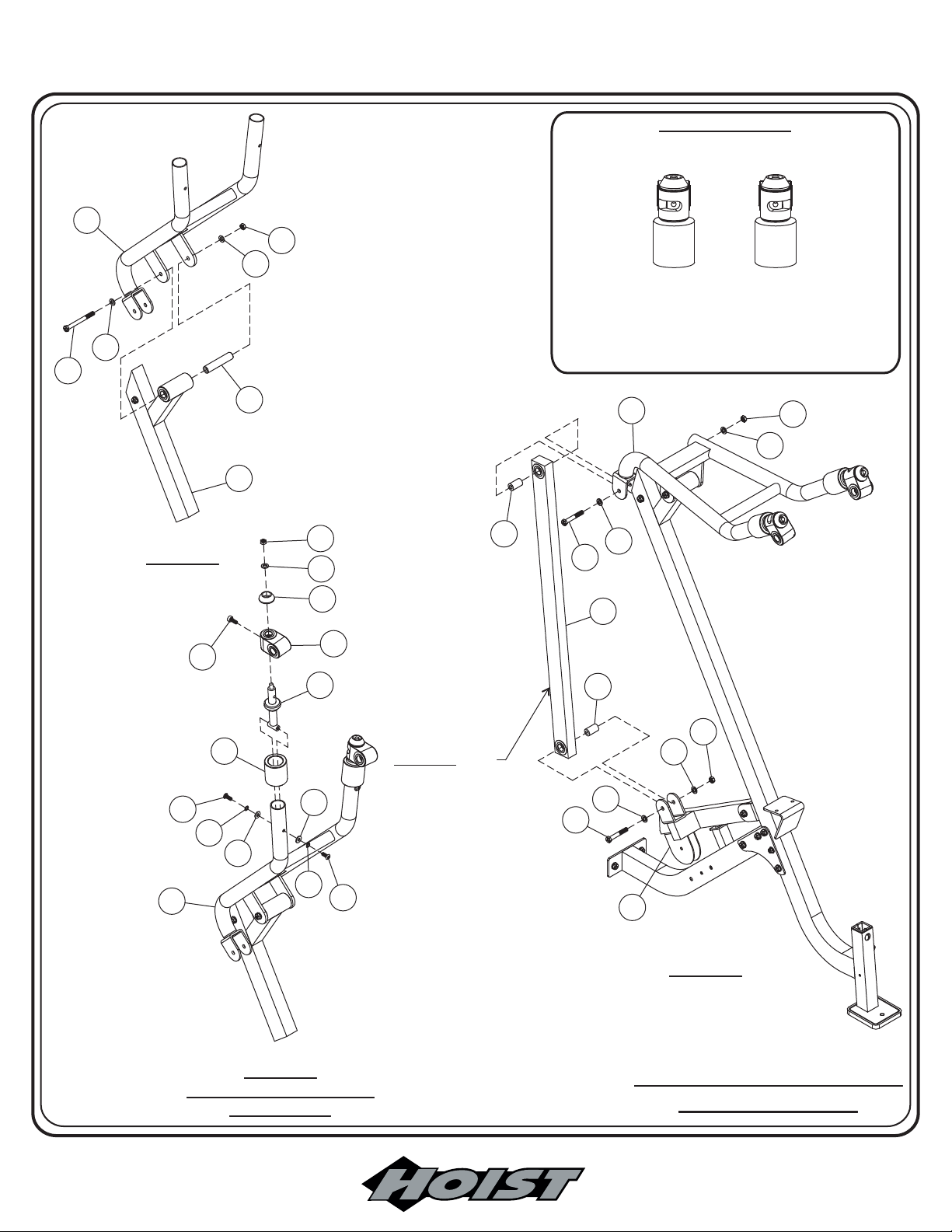
Step 2c
FRAME ASSEMBLY
Continue assembly by inserting (CE) into (6), then attach (10) to (CE).
Wrench Tighten NOTE:
freely. If not, turn back the nut on the bolt for the axle just enough so that the
Arm Assembly rotates freely. Slide a (CF) onto each tube end of (10). Then
install an (11) to each side capturing (CF) between (11) and Button Head Bolt
(F). bolts. Slide a (12) onto each (11).
for the correct rear slot positioning of (12). Install the range limiting bolt (F)
through the slots in each (12). bolts. Attach (CG) to the top
of each (12). the retaining nuts then turn the nuts back just
enough so that each (12) rotates freely. Now insert both (CS)’s into (9), then
attach to (10) at the top and to (8) at the bottom. when attaching
(9) to (10), take special precaution when handling the arm. If released, the
front of (10) will swing up with a considerable amount of force, and could
cause bodily injury. bolts.
Assembly and the Weighted Connector rotates freely. If not, turn back the nut
on the bolt for the axle just enough so that the Arm Assembly and Weighted
Connector rotates freely.
Wrench Tighten See the Assembly Note
bolts. Check to see that the Arm Assembly rotates
Wrench Tighten
Wrench Tighten
WARNING:
Wrench Tighten NOTE: Check to see that the Arm
Part Descriptions
6 - Front Upright
8 - Resistance Lever Arm
9 - Weighted Connector
10 - Arm
11 - Handle Assembly
12 - Bearing Housing
Hardware Descriptions
C - 1/2”-13UNC x 3 1/4” Hex Head Bolt (WZ)
E - 1/2”-13UNC x 6” Hex Head Bolt (WZ)
F - 3/8”-16UNC x 3/4” Button Head Bolt (WZ)
R - 3/8”-16UNC x 1” Socket Head cap Screw
AA - 1/2” Washer
AB - 3/8” Washer
AE - 3/8” Lock Washer
BA - 1/2” Nylok Nut
CS - 19mm dia. x 57.5mm lg. Axle
CE - 25.4mm dia. x 120mm lg. Axle
CF - Rubber Sleeve
CG - Aluminum Bolt on Cap
Page - 9
HD1700 Assembly
OWNERS
MANUAL
ASSEMBLY NOTE:ASSEMBLY NOTE:
This view is shown from the rear for clarityThis view is shown from the rear for clarity
10
BA
AA
This view shows the proper positioning of assembly
This view shows the proper positioning of assembly
Notice how the slots in these assemblies are not
12. Notice how the slots in these assemblies are not
12.
centered
centered with the part but have been rotated more
to
AA
to one side instead. The sides of the parts which
contain
contain more of the slot are positioned to the inside.
E
with the part but have been rotated more
one side instead. The sides of the parts which
more of the slot are positioned to the inside.
STEP -1-STEP -1-
R
F
AE
10
CF
AB
6
CE
AB
AE
BA
AA
CG
11
12
10
BA
AA
CS
AA
C
9
CS
BA
WARNING: when
WARNING: when
attaching (9) to (10),
attaching
take
take special precaution
when
when handling the
arm.
arm. If released, the
front
front of (10) will swing
up
up with a considerable
amount
amount of force and
could
F
could cause bodily
injury,
injury, or damage the
machine.
machine.
(9) to (10),
special precaution
handling the
If released, the
of (10) will swing
with a considerable
of force and
cause bodily
or damage the
AA
C
AA
8
STEP -2-
STEP -2-
NOTE: REPEAT ASSEMBLY ON
NOTE: REPEAT ASSEMBLY ON
OPPOSITE SIDE.
OPPOSITE
SIDE.
STEP -3-STEP -3-
*ASSEMBLY SHOWN IN THREE
*ASSEMBLY SHOWN IN THREE
STEPS FOR CLARITY.
STEPS
FOR CLARITY.
Page - 10HD1700 Assembly
OWNERS
MANUAL
Step 2d
WEIGHT STACK ASSEMBLY
Continue assembly by attaching (14) and (CK) to (6). Now slide (15)
through (CH) and slide them both into (3). Tilt both (15)’s forward
enough to allow room to slide the Weight Plates on. Slide all 10 (22)’s and
all 5 (23)’s onto both (15)’s. Now slide (24) onto both (15)’s. Slide (13)
over both (15)’s. Angle both (15)’s vertical and secure (13) to both (1) and
(2). Secure both (15)’s to (13) using set screw (U). bolts.Wrench Tighten
Part Descriptions
1 - Weight frame Upright
2 - Top Pulley Mount
3 - Weight Stack Mount
6 - Front Upright
13 - Guide Rod Top Mount
14 - Latch Assembly
15 - Guide Rod
22 - 20 lb. Intermediate Weight
23 - 12 1/2 lb. Intermediate Weight
24 - 8 1/4 lb. Top Plate
Hardware Descriptions
C - 1/2”-13UNC x 3 1/4” Hex Head Bolt (WZ)
G - 3/8”-16UNC x 3/4” Square Head Set Screw
U - 5/16”-18UNC x 5/16”-Scocket Set Screw
AA - 1/2” Washer
BA - 1/2” Nylok Nut
CH - Weight Stack Bumper
CK - Latch Spring
CL - Latch Pin
CM - C-Clip
Page - 11
HD1700 Assembly

OWNERS
MANUAL
C
AA
2
1
U
14
CK
CL
G
CM
6
U
24
1
3
15
13
AA
BA
23
22
15
CH
Page - 12HD1700 Assembly
OWNERS
MANUAL
Step 2e
FRAME ASSEMBLY
Continue assembly by inserting (CP) into (CN). Then attach both to
(27). Now attach (27) to (16). Insert (CB) into (12) and attach (16) to
(12). bolts. Check to see that the Handle
Wrench Tighten NOTE:
Weldment and U-Bracket rotates freely. If not, turn back the nut on the
bolt for the axle just enough so that the Handle Weldment and U-Bracket
rotates freely.
Part Descriptions
12 - Bearing Housing
16 - U-Bracket
27 - Handle Weldment
Hardware Descriptions
H - 1/2”-13UNC x 3 1/2” Hex Head Bolt (WZ)
J - 5/16”-18UNC x 1” Button Head Bolt (WZ)
AA - 1/2” Washer
AC - 5/16” Washer
AF - 5/16” Lock Washer
BA - 1/2” Nylok Nut
Page - 13
CB - 25.4mm dia. x 63mm lg. Axle
CN - Handle
CP - 25.4mm dia. x 148mm lg. Axle
CQ - 3/4” Thrust Washer
CR - 3/4” Thrust Bearing
HD1700 Assembly
 Loading...