

Hoist Fitness HD-1400 User Manual
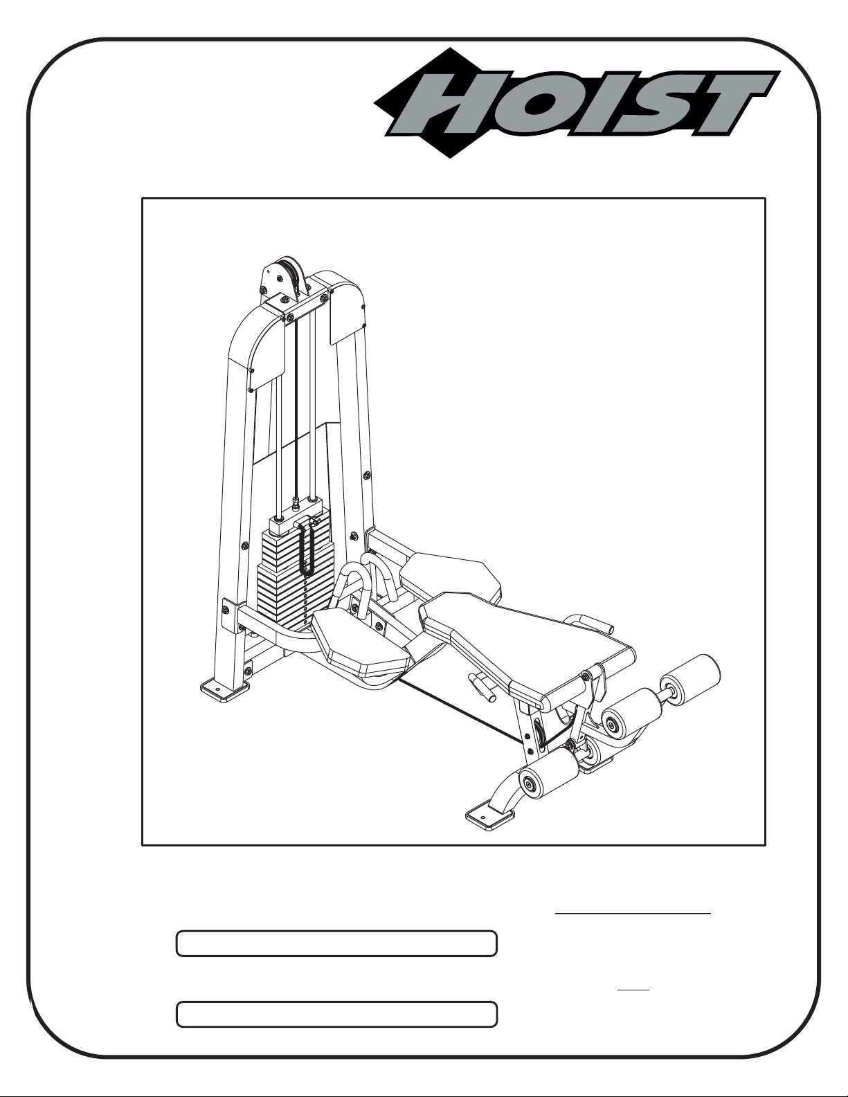
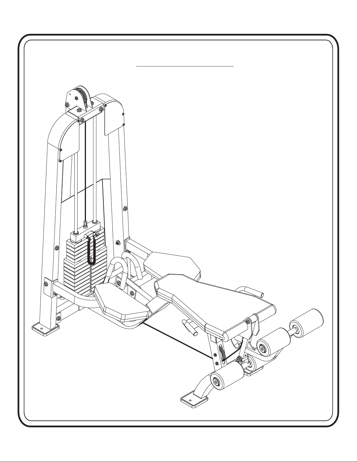
HD1400
LEG EXTENSION/CURL
Note: Both Serial Number and Model Number are Required when Ordering Parts
RECORD SERIAL NUMBER HERE
CATALOG NUMBER
OWNERS MANUAL
0302-001
Customer Service
(800) 548-5438
(858) 578-7676
Fa x
(858) 578-9558

OWNERS
MANUAL
CONTENTS
INSTRUCTIONS (Step 1)..............................................................
FRAME ASSEMBLY (Step 2).........................................................
CABLE ASSEMBLY (Step 3)..........................................................
SHIELD ASSEMBLY (Step 4).........................................................
PRE-ASSEMBLED PARTS (Step 5)................................................
PARTS LISTING ............................................................................
HARDWARE LISTING ..................................................................
BOLT SIZING CHART ..................................................................
WASHER SIZING CHART ............................................................
2
4
15
17
19
21
22
23
25
WEIGHT RATIOS............................................................................
WEIGHT TRAINING TIPS.............................................................
WEIGHT TRAINING EXERCISE LOG ......................................
DECAL PLACEMENT ...................................................................
GENERAL MAINTENANCE INFORMATION ............................
MAINTENANCE SCHEDULE........................................................
LIMITED WARRANTY ..................................................................
27
29
31
33
37
39
40
Page - 1
HD1400 Assembly

OWNERS
MANUAL
INSTRUCTIONS
Before beginning assembly please take the time to read the
instructions thoroughly. Please use the various lists in this
manual to make sure that all parts have been included in your
shipment.
from the lists.
Failure to do so will void your warranty and could result in
personal injury.
Hoist equipment is designed to provide the smoothest, most
effective exercise motion possible. After assembly, you should
check all functions to ensure correct operation. If you
experience problems, first recheck the assembly instructions to
locate any possible errors made during assembly. If you are
unable to correct the problem, call your authorized Hoist dealer.
Be sure to have your serial number and this manual when
calling. When all parts have been accounted for, continue on .
When ordering use the part number and description
Use only Hoist replacement parts when servicing.
TOOLS REQUIRED
Socket Wrench
(9/16”, 1/2”)
3/4" Open End Wrench
Standard Allen Wrench set
(5/64” thru 1/4”)
External snap ring pliers with a
tip size between .035" ~ .043".
Crescent Wrench
Rubber Mallet
Tape Measure
Page - 2HD1400 Assembly

O W N E R S
M A N U A L
***THIS PAGE WAS INTENTIONALLY LEFT BLANK******THIS PAGE WAS INTENTIONALLY LEFT BLANK***
Page - 3
HD1400 Assembly
OWNERS
MANUAL
Step 2
FRAME ASSEMBLY
Page - 4HD1400 Assembly

OWNERS
MANUAL
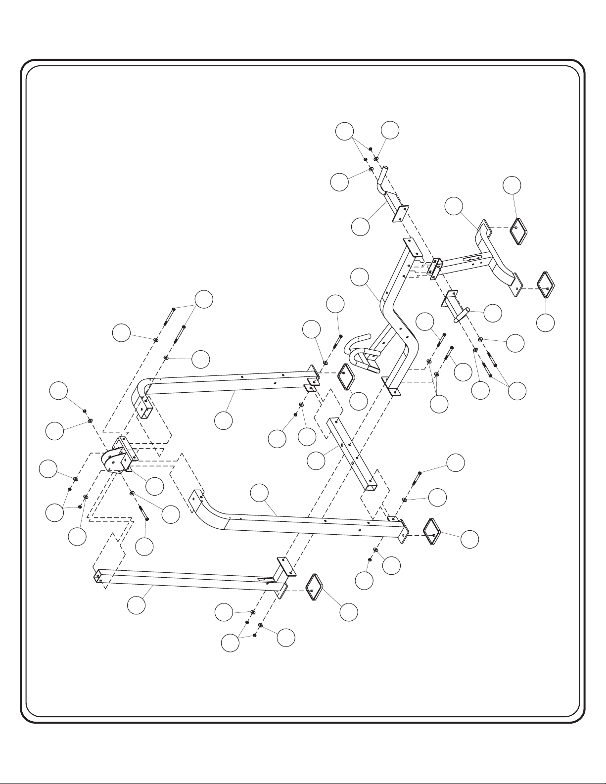
Step 2a
FRAME ASSEMBLY
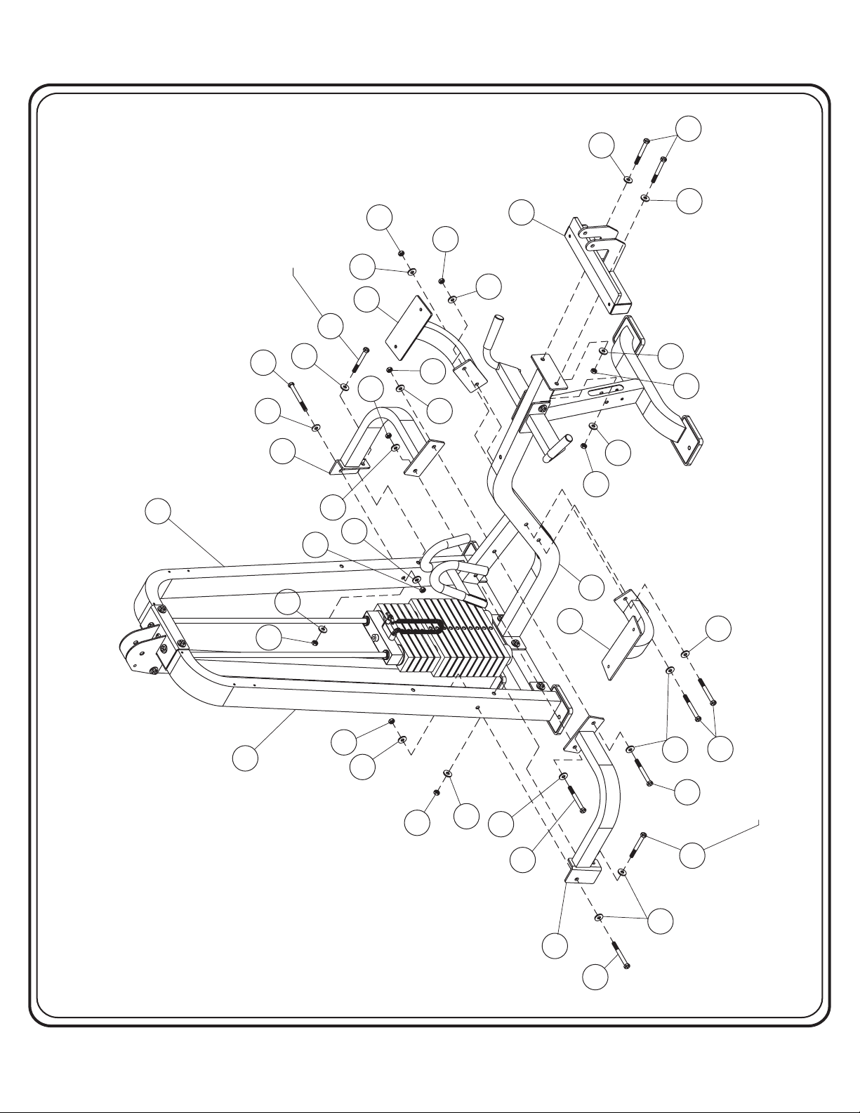
Start assembly by bolting both (1)’s, to (2). Then bolt (3) to the
bottom of both (1)’s. Attach the top of (5) to (2), and the bottom of (5)
and (4) to (3). Bolt (6), (7), and (8) to (4). bolts.Wrench Tighten
Part Descriptions
1 - Weight Frame Upright
2 - Weight Cage Top Mount
3 - Weight Stack Mount
4 - Main Support Frame
5 - Rear Upright
6 - Main Frame Support
7 - Right Side Handle
8 - Left Side Handle
Hardware Descriptions
A - 1/2”-13UNC x 4 3/4” Hex Bolt
B - 1/2”-13UNC x 3” Hex Bolt
E - 1/2”-13UNC x 3 1/4” Hex Bolt
AA - 1/2” Flat Washer
BA - 1/2” Nylok Nut
CA - Rubber Foot Pad
Page - 5
HD1400 Assembly
OWNERS
MANUAL
BA
AA
AA
A
AA
BA
AA
8
4
B
AA
CA
1
BA
AA
AA
CA
6
AA
7
CA
AA
E
B
B
AA
AA
BA
AA
3
2
AA
B
5
AA
BA
1
AA
BA
CA
AA
B
AA
CA
Page - 6HD1400 Assembly

OWNERS
MANUAL
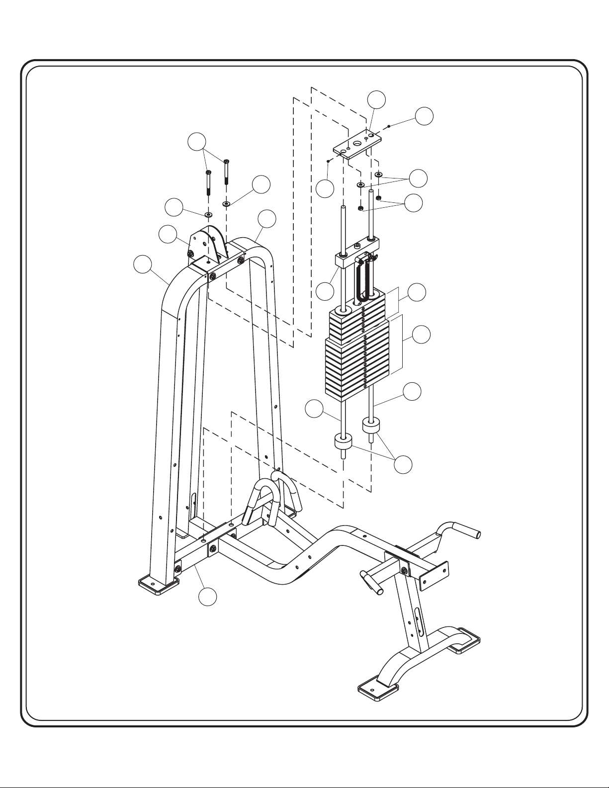
Step 2b
FRAME ASSEMBLY
Start by sliding (9) through (CB) and slide them both into (3). Tilt
both (9)’s forward enough to allow room to slide the weights on. Slide all
10 (10)’s, and all 5 (11)’s on to both (9)’s. Now slide (12) onto both (9)’s.
Slide (CG) on both (9)’s and angle both (9)’s vertical and secure (CG) to
both (1)’s and (2). Secure both (9)’s to (CG) using set screw (N). Wrench
Tighten all bolts.
Part Descriptions
1 - Weight Frame Upright
2 - Weight Cage Top Mount
3 - Weight Stack Mount
9 - Guide Rod
10 - 12 ½ LB Intermediate Plate
11-8¼LBIntermediate Plate
12-8¼LBTopPlate
Hardware Descriptions
E - 1/2”-13UNC x 3 1/4” Hex Bolt
N - 5/16”-UNC x 5/16” Socket Set Screw (WZ)
AA - 1/2” Flat Washer
BA - 1/2” Nylok Nut
CB - Weight Stack Bumper
CG - Guide Rod Top Mount
Page - 7
HD1400 Assembly
OWNERS
MANUAL
CG
N
E
AA
AA
1
2
1
N
12
9
AA
BA
11
10
9
CB
3
Page - 8HD1400 Assembly

OWNERS
MANUAL
Step 2c
FRAME ASSEMBLY
Start assembly by bolting (13) and (14) to (1) and (4). Then bolt (15)
and (16) to (4). Bolt (17) to (4). bolts. when
Wrench Tighten Note:
bolting (13) and (14) to both (1)’s, hand tighten bolts (A), they will be
secured in a later step.
Part Descriptions
1 - Weight Frame Upright
4 - Main Frame
13 - Left Side Support Mount
14 - Right Side Support Mount
15 - Left Side Elbow Pad Mount
16 - Right Side Elbow Pad Mount
17 - Leg Extension Mount
Hardware Descriptions
A - 1/2”-13UNC x 4 3/4” Hex Bolt
B - 1/2”-13UNC x 3” Hex Bolt
D - 1/2”-13UNC x 2 3/4” Hex Bolt
AA - 1/2” Flat Washer
BA - 1/2” Nylok Nut
Page - 9
HD1400 Assembly
OWNERS
MANUAL
bolt,
AA
step.
this
tightened
be
a later
tighten
will
in
in a later step.
they
they will be tightened
Hand tighten this bolt,
Hand
A
AA
D
AA
14
1
AA
BA
BA
BA
AA
16
BA
BA
AA
AA
17
AA
AA
BA
D
AA
AA
BA
4
AA
15
BA
1
BA
AA
BA
AA
AA
D
13
D
AA
AA
D
AA
bolt,
step.
this
tightened
B
a later
tighten
will be
in a later step.
in
they will be tightened
they
Hand tighten this bolt,
Hand
A
Page - 10HD1400 Assembly

OWNERS
MANUAL
Step 2d
FRAME ASSEMBLY
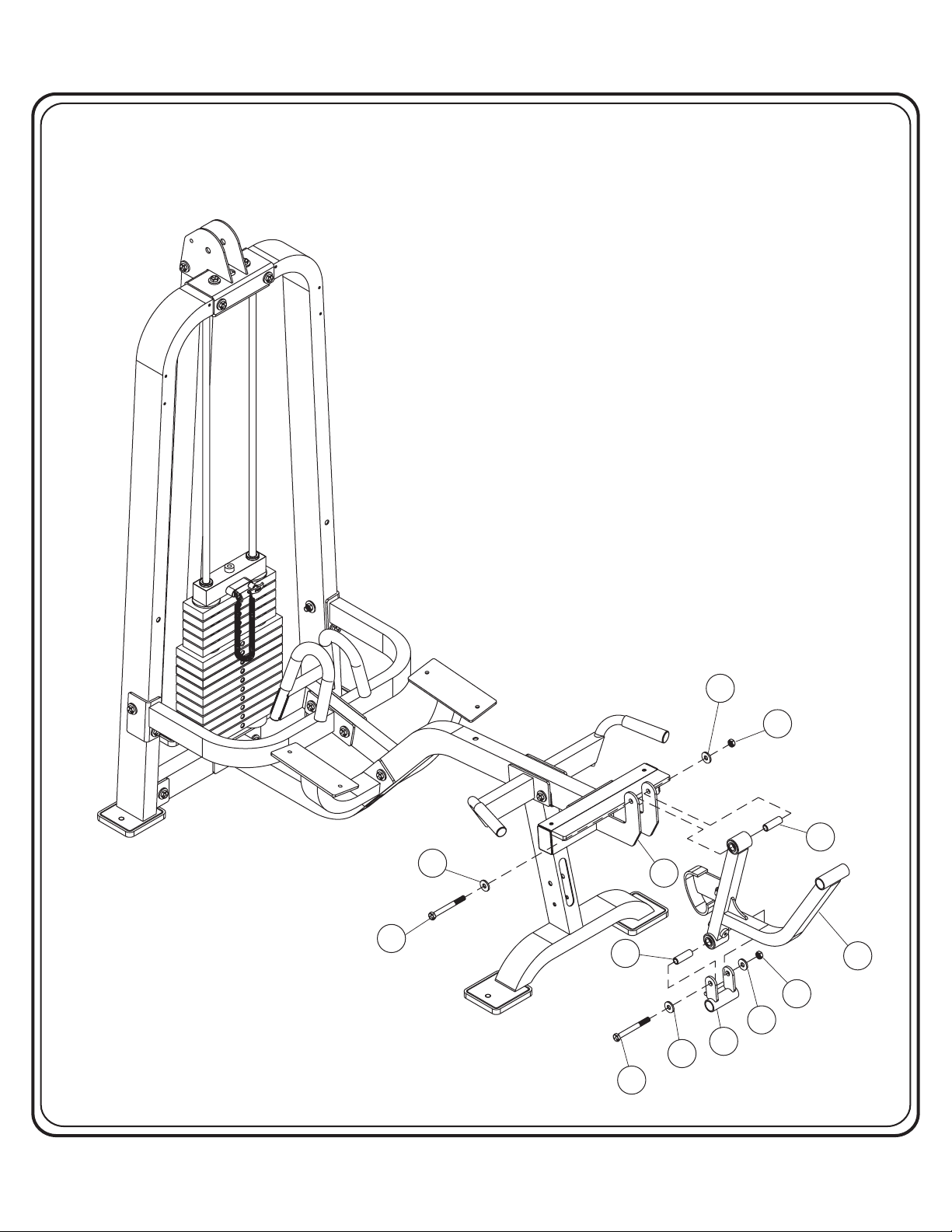
Start assembly by sliding (20) into the top of (18) and attach it to
(17). Then slide (20) into the bottom of (18) and attach (19) to (18).
Wrench Tighten
not, back off Nylock Nut (BA) slightly until both (18) and (19) swing
freely.
Part Descriptions
17 - Leg Extension Mount
18 - Leg Extension
19 - Lower Swivel Bracket
20 - Dia. .75 x 2.25 LG CRS
bolts. Check to see that these pivot areas swing freely. If
Hardware Descriptions
E - 1/2”-13UNC x 3 1/4” Hex Bolt
AA - 1/2” Flat Washer
BA - 1/2” Nylok Nut
Page - 11
HD1400 Assembly
OWNERS
MANUAL
AA
BA
20
AA
E
20
17
18
BA
AA
19
AA
E
Page - 12HD1400 Assembly
 Loading...