

Hoist Fitness CL-2601 User Manual
RR
O
FITNESS SYSTEMS
I
SH
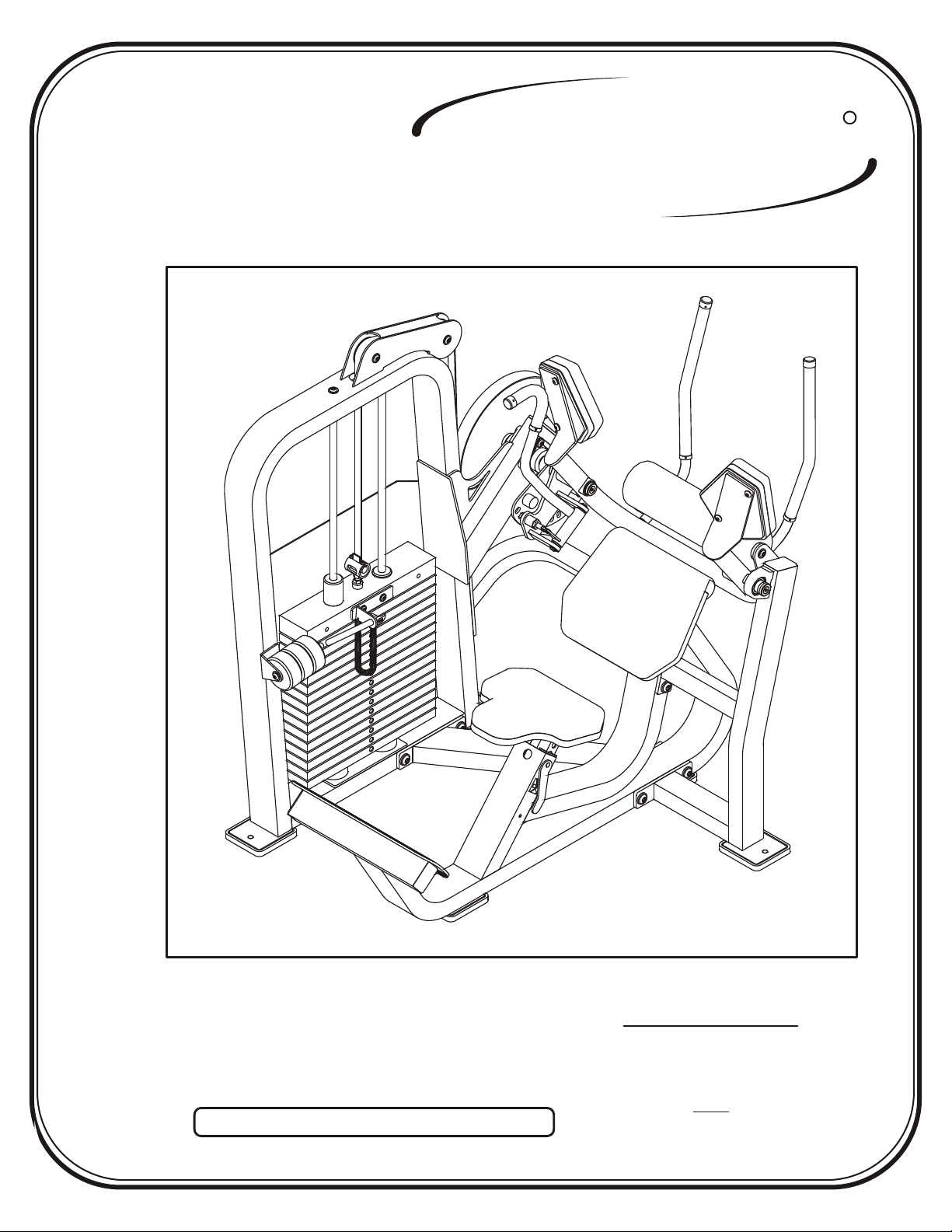
CL-2601
T
RECORD SERIAL NUMBER HERE
OWNERS MANUAL
June 2000
Note: Both Serial Number and Model Number are Required when Ordering Parts
Customer Service
(800) 548-5438
(619) 578-7676
Fax
(619) 578-9558

A S S E M B LY
I N S T R U C T I O N S
CONTENTS
INSTRUCTIONS (Step 1) .............................................................
FRAME ASSEMBLY (Step 2) ........................................................
PARTS LISTING ............................................................................
HARDWARE LISTING ..................................................................
BOLT SIZING CHART ..................................................................
WASHER SIZING CHART ............................................................
WEIGHT RATIOS .........................................................................
WEIGHT TRAINING TIPS ...........................................................
WEIGHT TRAINING EXERCISE LOG .......................................
2
4
27
28
29
30
32
33
35
Page 1
DECAL REFERENCE ...................................................................
GENERAL MAINTENANCE .........................................................
LIMITED WARRANTY ..................................................................
RR
O
H I
FITNESS SYSTEMS
S
T
2601 Assembly
37
39
42

A S S E M B LY
I N S T R U C T I O N S
Step 1
I N S T R U C T I O N S
Before beginning assembly please take the time to read the
instructions thoroughly. Please use the catalog in this manual to
make sure that all parts have been included in your shipment.
When ordering use the part number and description from the
catalog.
to do so will void your warranty and could result in personal
injury.
effective exercise motion possible. After assembly, you should
check all functions to ensure correct operation. If you
experience problems, first recheck the assembly instructions to
locate any possible errors made during assembly. If you are
unable to correct the problem, call your authorized Hoist dealer.
Be sure to have your serial number and this catalog when calling.
When all parts have been accounted for, continue on to Step 2.
Use only Hoist replacement parts when servicing. Failure
Hoist equipment is designed to provide the smoothest, most
TOOLS REQUIRED
Standard Allen Wrench Set
(2.5mm 3/32” - 5/16”)
Belt Tensioning Wrench
Crescent Wrench
Belt Tensioning Wrench
(Hoist Tool SM374)
Rubber Mallet
Tape Measure
RR
O
H I
FITNESS SYSTEMS
S
T
Page - 22601 Assembly

A S S E M B LY
I N S T R U C T I O N S
Page 3
O
H I
FITNESS SYSTEMS
S
T
RR
2601 Assembly
A S S E M B LY
I N S T R U C T I O N S
Step 2
F R A M E A S S E M B L Y
FACTORY INSTALLATION INSTRUCTION ONLY
1. ALL THREADED HOLES SHOULD BE TAPPED,
EXCEPT INSERTS.
2. ALL CALLED INSERTS MUST BE INSTALLED BEFORE ANY
ASSEMBLY.
H T
OIS
FITNESS SYSTEMS
RR
Page - 42601 Assembly

A S S E M B LY
I N S T R U C T I O N S
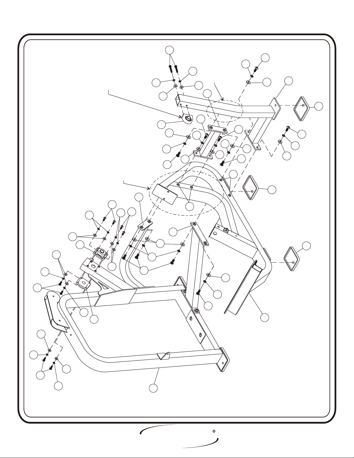
Step 2a
F R A M E A S S E M B L Y
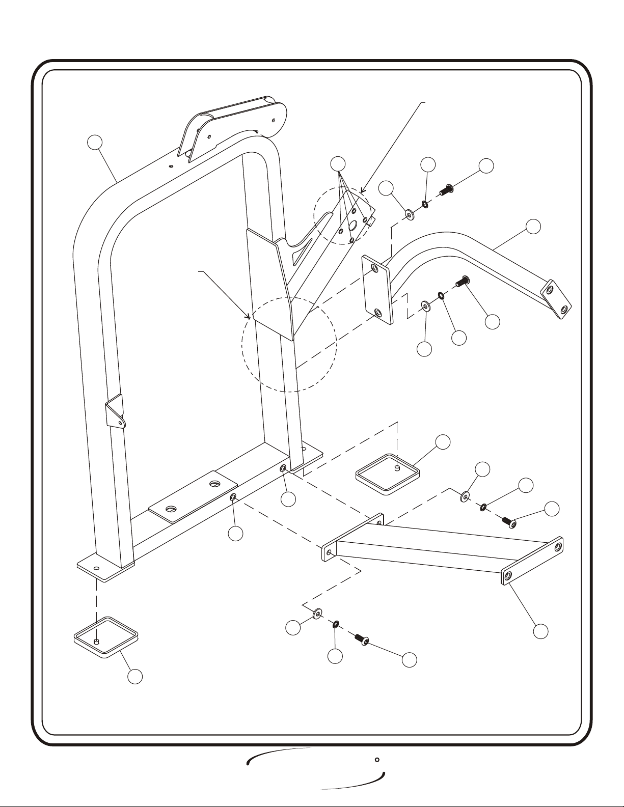
(Factory Installation) Insert (CA) and (CB) into (1). Attach (1) to
(2). Then (3) to (1). Hand tighten bolts only, they will be tightened later.
Lift machine to position (4).
Part Descriptions
1 - Weight Cage
2 - Mount Assembly
3 - Bottom Mount Assembly
4 - Rubber Foot Pad
Hardware Descriptions
A - 1/2”-13 x 1 1/2” Button Head Screw (White Zinc)
AA - 1/2” Lock Washer (White Zinc)
AB - 1/2” Flat Washer (White Zinc)
CA - Insert 1/2”
CB - Insert 3/8”
Page 5
O
H I
FITNESS SYSTEMS
S
T
RR
2601 Assembly
A S S E M B LY
I N S T R U C T I O N S
Factory install 4
Factory install 4
threaded inserts
threaded inserts
(CB) to weight cage.
(CB) to weight cage.
11
Factory install 2
Factory install 2
threaded inserts
threaded inserts
(CA) to weight cage.
(CA) to weight cage.
CBCB
ABAB
ABAB
AAAA
AA
2
2
AA
AAAA
44
ABAB
AAAA
CACA
CA CA
ABAB
AAAA
44
RR
H T
OIS
FITNESS SYSTEMS
AA
AA
33
Page - 62601 Assembly

A S S E M B LY
I N S T R U C T I O N S
Step 2c
F R A M E A S S E M B L Y
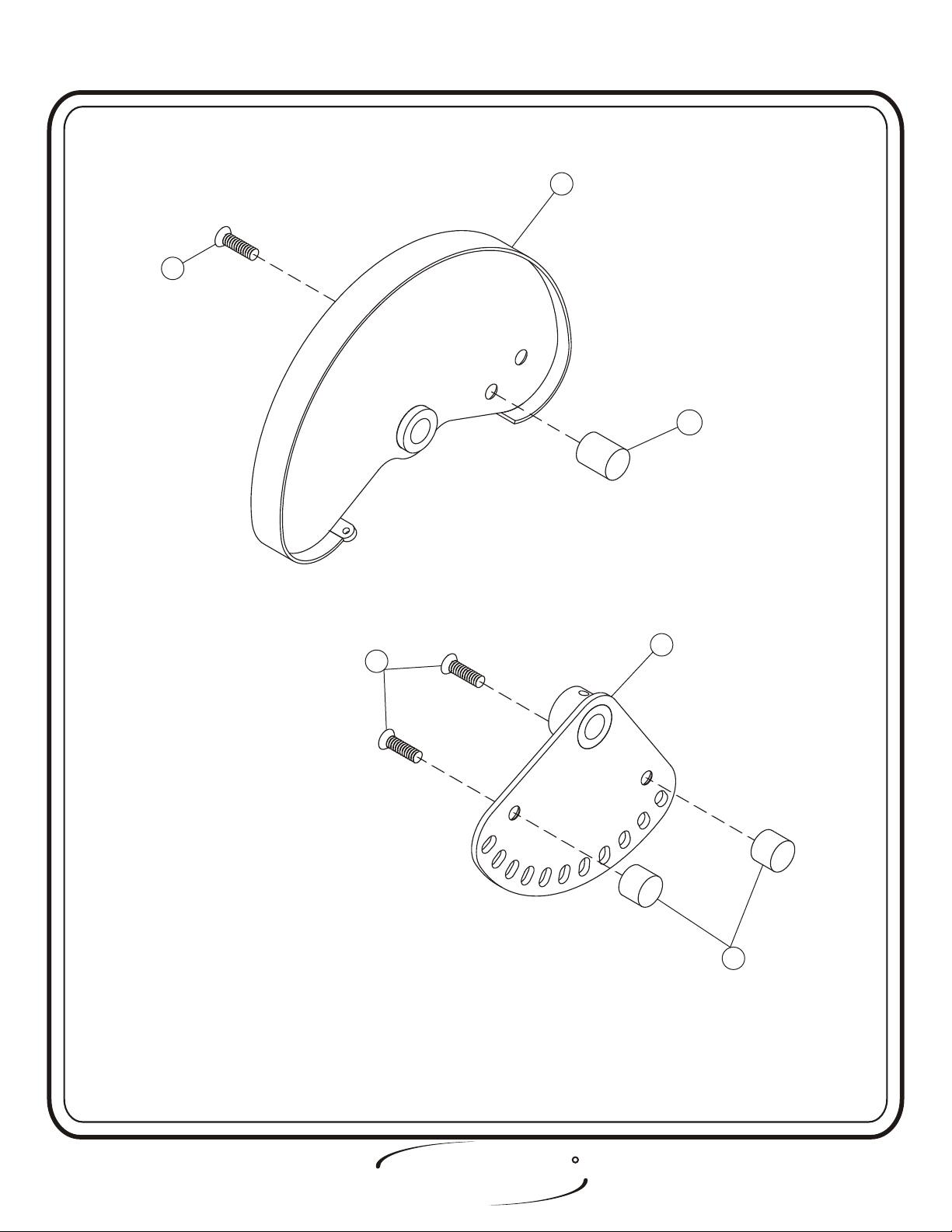
Attach one (DW) to (10), and two (DX)’s to (9) Wrench tighten
bolts.
Part Descriptions
9 - Range of Motion
10 - Cam Assembly Large
.
Hardware Descriptions
S - 1/2”-13 x 3/4” Flat Head Screw
T - 1/2”-13 x 1” Flat Head Screw
DW - Dia. 1 1/4” x 1 1/2” Delrin
DX - Dia. 1 1/4” x 1” Delrin
Page 7
O
H I
FITNESS SYSTEMS
S
T
RR
2601 Assembly
A S S E M B LY
I N S T R U C T I O N S
1010
T
T
DWDW
99
S
S
DXDX
H T
OIS
FITNESS SYSTEMS
RR
Page - 82601 Assembly

A S S E M B LY
I N S T R U C T I O N S
Step 2b
F R A M E A S S E M B L Y
(Factory Installation) Insert (CE) into (1), and (CA) into (5). Attach
(5) to (2) and (3). Next, attach (7) to (5), then (6) to (5) and (7). Now,
attach two (CE)’s to (1); then, (CD) to (6), insuring the set screws are
facing inwards toward (1) . Hand tighten bolts only, they will be
tightened later. Lift machine to position (4).
Part Descriptions
1 - Weight Cage
2 - Mount Assembly
3 - Bottom Mount Assembly
4 - Rubber Foot Pad
5 - Seat Frame Assembly
6 - Seat Support Mount
7 - Seat Mount Support
Hardware Descriptions
A - 1/2”-13 x 1 1/2” Button Head Screw (White Zinc)
B - 3/8”-16 x 1 1/4” Button Head Screw
C - 3/8”-16 x 3 1/2” Button Head Screw (White Zinc)
AA - 1/2” Lock Washer (White Zinc)
AB - 1/2” Flat Washer (White Zinc)
AE - 3/8” Flat Washer
AF - 3/8” Flat Washer (
CA - Insert 1/2”
CD - Pillow Block Bearing
CE - 4 Hole Flange Bearing
White Zinc)
Page 9
O
H I
FITNESS SYSTEMS
S
T
RR
2601 Assembly
A S S E M B LY
I N S T R U C T I O N S
CC
AFAF
TOWARDS (1).
TOWARDS (1).
FACING INWARD
FACING INWARD
FOR SET SCREWS ARE
FOR SET SCREWS ARE
INSURE TAPPED HOLES
INSURE TAPPED HOLES
Factory install 4
Factory install 4
threaded inserts
threaded inserts
(CA) to Seat Frame
(CA) to Seat Frame
AFAF
AEAE
CDCD
ABAB
AAAA
AA
Assembly (5).
Assembly (5).
AEAE
77
AA
AAAA
ABAB
AA
AAAA
Mount (6).
Mount (6).
Factory install 4
Factory install 4
threaded inserts
threaded inserts
(CA) to Seat Support
(CA) to Seat Support
AA
AAAA
ABAB
ABAB
AA
CACA
ABAB
66
44
AA
AAAA
ABAB
44
22
BB
BB
ALAL
AKAK
CECE
AKAK
ALAL
BB
ALAL
CECE
AKAK
ALAL
ALAL
ABAB
AAAA
AKAK
AA
CACA
33
44
ABAB
AAAA
AA
55
BB
AKAK
ALAL
11
H T
OIS
FITNESS SYSTEMS
RR
Page - 102601 Assembly

A S S E M B LY
I N S T R U C T I O N S
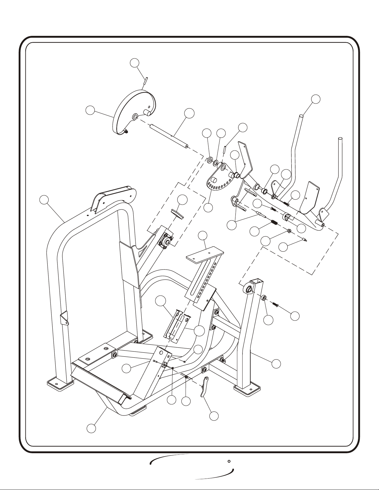
Step 2c
F R A M E A S S E M B L Y
ress two (CJ)’s into (8).
P Attach (10) to (CH), then slide (CH)
through (1) and attach to (9). Next, slide one side of (8) onto (CH), then
slide the other side of (8) through (6)
and secure. Attach (13) to (8) and
secure. Attach two (CM)’s to (5), and slide (11) into (5). Attach (12) to
(5). Secure (CN) to (8) and attach (CP) to (CN).
Hand tighten bolts only,
they will be tightened later.
Part Descriptions
1 - Weight Cage
5 - Seat Frame Assembly
6 - Seat Support Mount
8 - Arm Support Assembly
9 - Range of Motion
10 - Cam Assembly Large
11 - Seat Adjuster
12 - Latch Assembly
13 - Aluminum Cap (Red Anodized)
Hardware Descriptions
D - 3/8”-16 x 1 1/4” Flat Head
R - Set Screw
CF - 3/8” x 2” Open Roll Pin
CG - Aluminum Cap
CH - 1.00 Dia. 13.609 Shaft
CJ - 1” OD Oilite Bushing
CK - Adjustment Spring
CL - 1/4” OD Pivot Shaft
CM - EZ-Glide Sleeve
CN - 1/2” Short Pull Pin
CP - Pull-Pin to Chain Link Connector
CQ - 2 x 4 End Cap
CR - 1/4” C-Clip
DR
- 3/8” Flat Head Cap (Red Anodized)
Page 11
O
H I
FITNESS SYSTEMS
S
T
RR
2601 Assembly
A S S E M B LY
I N S T R U C T I O N S
CFCF
88
1010
11
CQCQ
CHCH
1111
DSDS
CNCN
CJCJ
CFCF
FBFB
CJCJ
DRDR
DD
DD
1313
CNCN
CPCP
DTDT
99
CMCM
CGCG
CMCM
RR
CLCL
CRCR
CKCK
1212
55
RR
H T
OIS
FITNESS SYSTEMS
DD
6
6
Page - 122601 Assembly

A S S E M B LY
I N S T R U C T I O N S
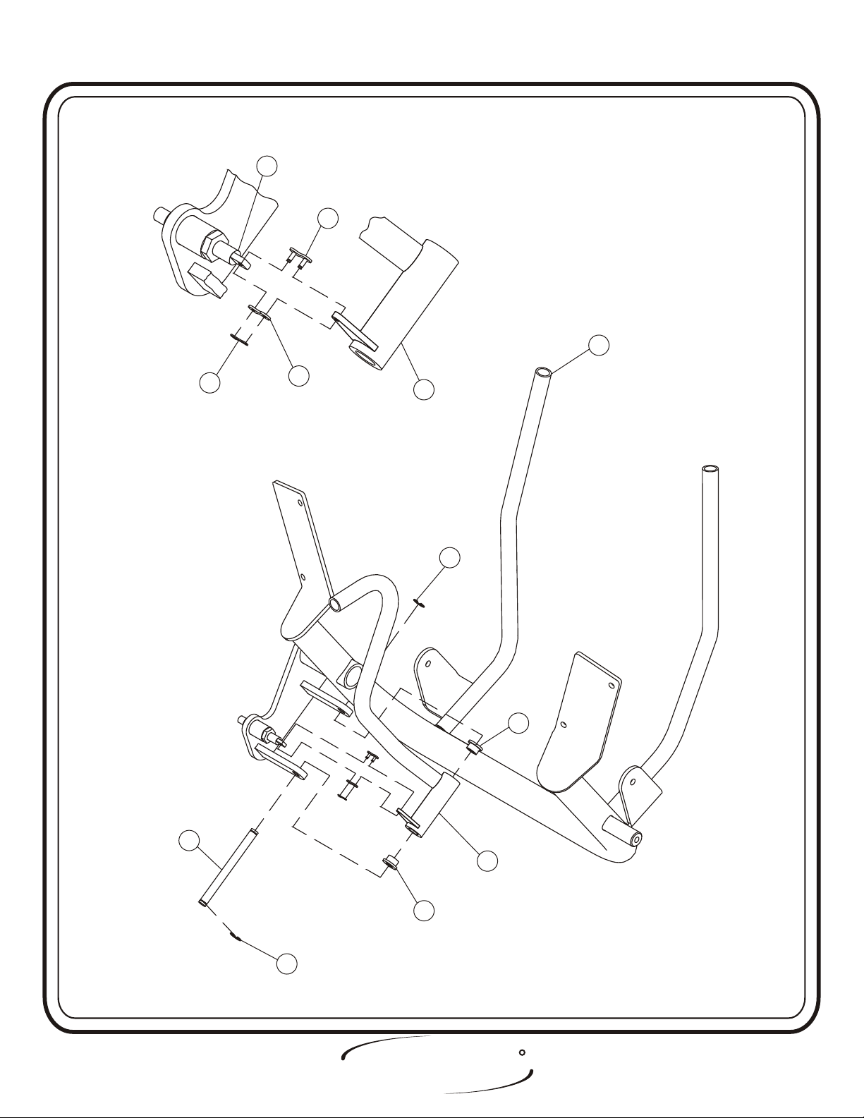
Step 2d
F R A M E A S S E M B L Y
ress two (CX)’s into (23).
P Attach (23) to (8), then (DA) to both (CP)
and (23). Hand tighten bolts only, they will be tightened later.
Part Descriptions
8 - Arm Support Assembly
23 - Handle Assembly
24 - .5 Dia Shaft
Hardware Descriptions
CP - Pull-Pin to Chain Link Connecter
CX - 1/2” Oilite Bearing
CZ - 1/2” C-Clip
DA - Master Chain Link
Page 13
O
H I
FITNESS SYSTEMS
S
T
RR
2601 Assembly
A S S E M B LY
I N S T R U C T I O N S
CPCP
DADA
88
DADA
DADA
2323
CZCZ
CXCX
2424
CZCZ
2323
CXCX
H T
OIS
FITNESS SYSTEMS
RR
Page - 142601 Assembly

A S S E M B LY
I N S T R U C T I O N S
Step 2e
F R A M E A S S E M B L Y
In this step start by pressing
(17) in (1), then place (18) over (17)
and insure holes are lined up. Next slide in two (16)’s in (1). Slide fifteen
(19)’s and one (20) onto both (16)’s. Make sure the weight stack and its
guide rods are sitting level and bolt the tops of (16) to (1). Attach (14) to
(21) and secure (21) to (20),then press two (31)’s in each of the three
(22)’s and slide on three (22)’s on to (21). Next attach (14) to (1). Attach
the bigger end of (CT) to (21) and the other end to (15).
Wrench tighten
bolts including all previously hand tightened bolts.
Part Descriptions
1 - Weight Cage
14 - Add on Rods
15 - Weight Selector Pin
16 - Guide Rod
Hardware Descriptions
E - 5/16”-18 x 1” Button Head
F - 3/8”-16 x 1” Button Head
G - 3/8”-16 x 1” Button Head (White Zinc)
H - 3/8”-16 x 2 3/4” Button Head (White Zinc)
17 - Guide Rod Bushing
18 - Weight Bumpers
19 - 20 LB Intermediate Weight
20 - 15 LB Aluminum Top Plate
21 - Center LH BRK (Add on)
22 - 5 LB Add on Weight
31 - Bushing for Cast Add on Weight
AA - 1/2” Lock Washer
AE - 3/8” Flat Washer
AF - 3/8” Lock Washer
AG - 5/16” Flat Washer
AH - 5/16” Lock Washer
AJ - 3/8” Lock Washer
AK - 3/8” Flat Washer
CT - Selector Pin Lanyard
CV - Guide Bearing (Tall)
CW - Guide Bearing (Short)
Page 15
O
H I
FITNESS SYSTEMS
S
T
RR
2601 Assembly
 Loading...