

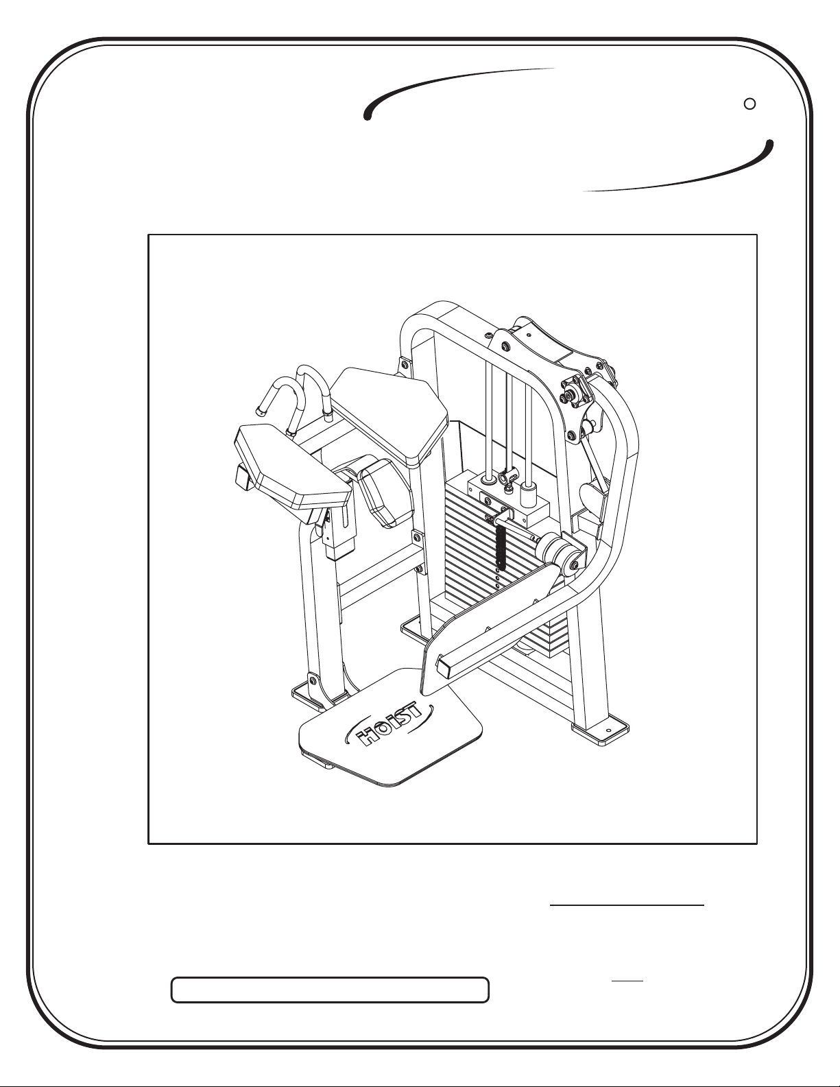
Hoist Fitness CL-2412 User Manual
HOIST
FITNESS SYSTEMS
CL-2412
R
Note: Both Serial Number and Model Number are Required when Ordering Parts
RECORD SERIAL NUMBER HERE
OWNERS MANUAL
July 2000
Customer Service
(800) 548-5438
(619) 578-7676
Fa x
(619) 578-9558

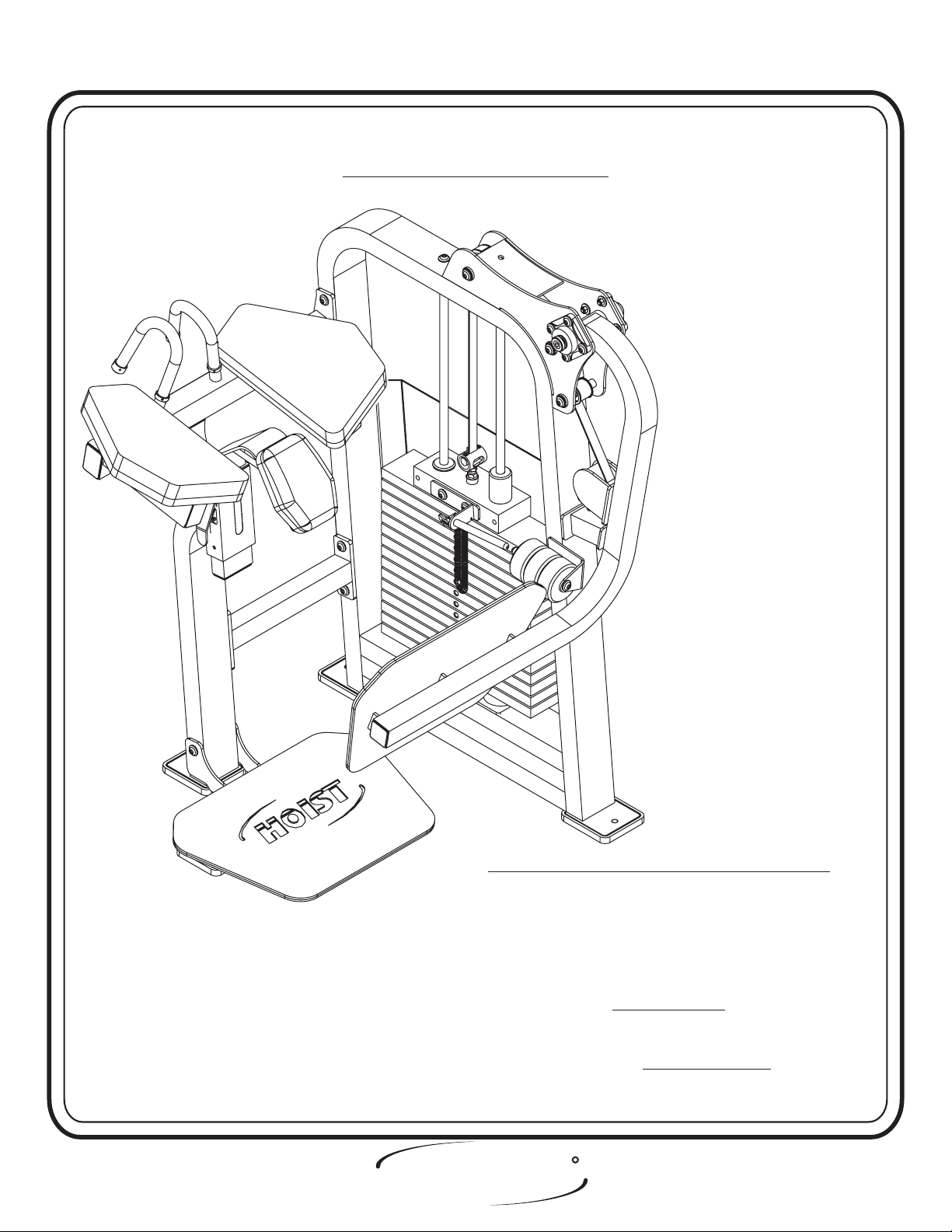
ASSEMBLY
INSTRUCTIONS
CONTENTS
INSTRUCTIONS (Step 1) .............................................................
FRAME ASSEMBLY (Step 2) ........................................................
PARTS LISTING ............................................................................
HARDWARE LISTING ..................................................................
BOLT SIZING CHART ..................................................................
WASHER SIZING CHART ............................................................
WEIGHT RATIOS .........................................................................
WEIGHT TRAINING TIPS ...........................................................
WEIGHT TRAINING EXERCISE LOG ......................................
2
4
23
24
26
27
28
30
32
Page 1
DECAL PLACEMENTS ..................................................................
GENERAL MAINTENANCE INFORMATION..............................
LIMITED WARRANTY ..................................................................
R
HOIST
FITNESS SYSTEMS
2412 Assembly
34
39
42

ASSEMBLY
INSTRUCTIONS
Step 1
INSTRUCTIONS
Before beginning assembly please take the time to read the
instructions thoroughly. Please use the catalog in this manual to
make sure that all parts have been included in your shipment.
When ordering use the part number and description from the
catalog.
Use only Hoist replacement parts when servicing. Failure
to do so will void your warranty and could result in personal
injury.
Hoist equipment is designed to provide the smoothest, most
effective exercise motion possible. After assembly, you should
check all functions to ensure correct operation. If you
experience problems, first recheck the assembly instructions to
locate any possible errors made during assembly. If you are
unable to correct the problem, call your authorized Hoist dealer.
Be sure to have your serial number and this catalog when calling.
When all parts have been accounted for, continue on to Step 2.
TOOLS REQUIRED
Standard Allen Wrench Set
(2.5mm, 3/32” - 5/16”)
Crescent Wrench
Belt Tensioning Wrench
(Hoist Tool SM374)
Rubber Mallet
Tape Measure
R
HOIST
FITNESS SYSTEMS
Page - 22412 Assembly

ASSEMBLY
INSTRUCTIONS
R
R
HOIST
HOIST
FITNESS SYSTEMS
Page - 3 2412 Assembly
FITNESS SYSTEMS
ASSEMBLY
INSTRUCTIONS
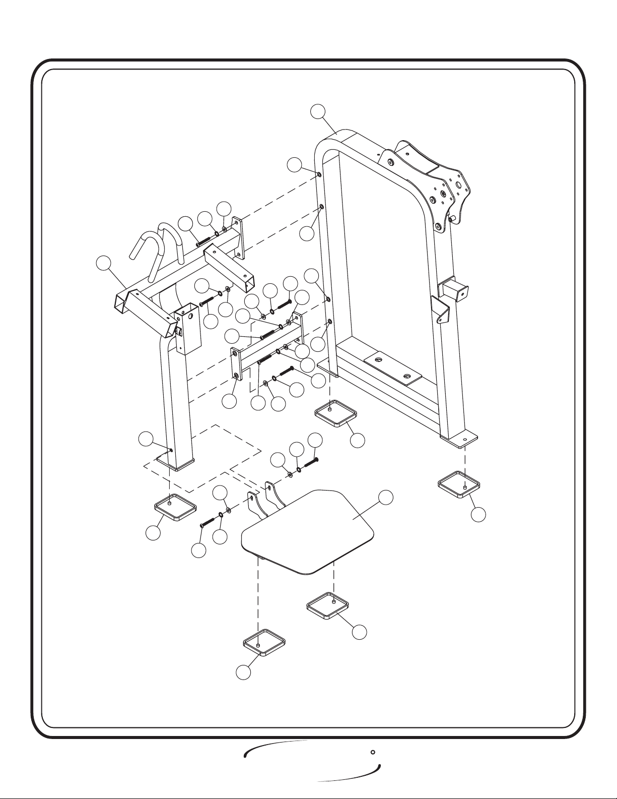
Step 2
FRAME ASSEMBLY
FACTORY INSTALLATION INSTRUCTION ONLY
1. ALL THREADED HOLES SHOULD BE TAPPED,
EXCEPT INSERTS.
2. ALL CALLED OUT INSERTS MUST BE INSTALLED BEFORE
ANY ASSEMBLY.
3. PUT A DROP OF ON BOLTS IF
NECESSARY.
4. IF NECESSARY APPLY TO ALL
BEARINGS.
HOIST
FITNESS SYSTEMS
BLUE LOCTITE 242
GREEN LOCTITE 680
R
Page - 42412 Assembly

ASSEMBLY
INSTRUCTIONS
Step 2a
FRAME ASSEMBLY
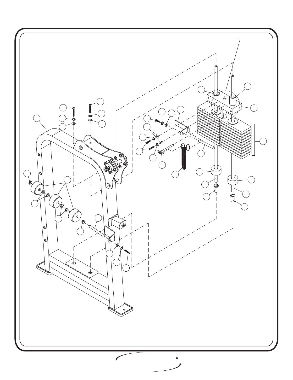
In this step start by attaching (7) to (5), then attach (6) to (7). Next,
attach (8) to (6). bolts only, they will be tightened later.
Hand Tighten
Lift machine to position (14).
Part Descriptions
5 - Weight Cage Assy.
6 - Arm Rest Assy.
7 - Cross Connector Assy.
8 - Foot Plate Assy.
14 - Rubber Foot Plate
Hardware Descriptions
A - 1/2-13 x 1 1/2” Button Head Screw
AA - 1/2” Internal Lock Washer
AG - 1/2” Flat Washer
CB - 1/2” Insert
Page 5
HOIST
FITNESS SYSTEMS
R
2412 Assembly
ASSEMBLY
INSTRUCTIONS
5
CB
AG
AA
AAA
6
AA
AG
A
A
7
AA
AG
AA
A
AG
AA
CB
AG
AG
AA
CB
CB
A
CB
14
A
AA
AG
AG
AA
A
14
14
8
14
14
HOIST
FITNESS SYSTEMS
R
Page - 62412 Assembly

ASSEMBLY
INSTRUCTIONS
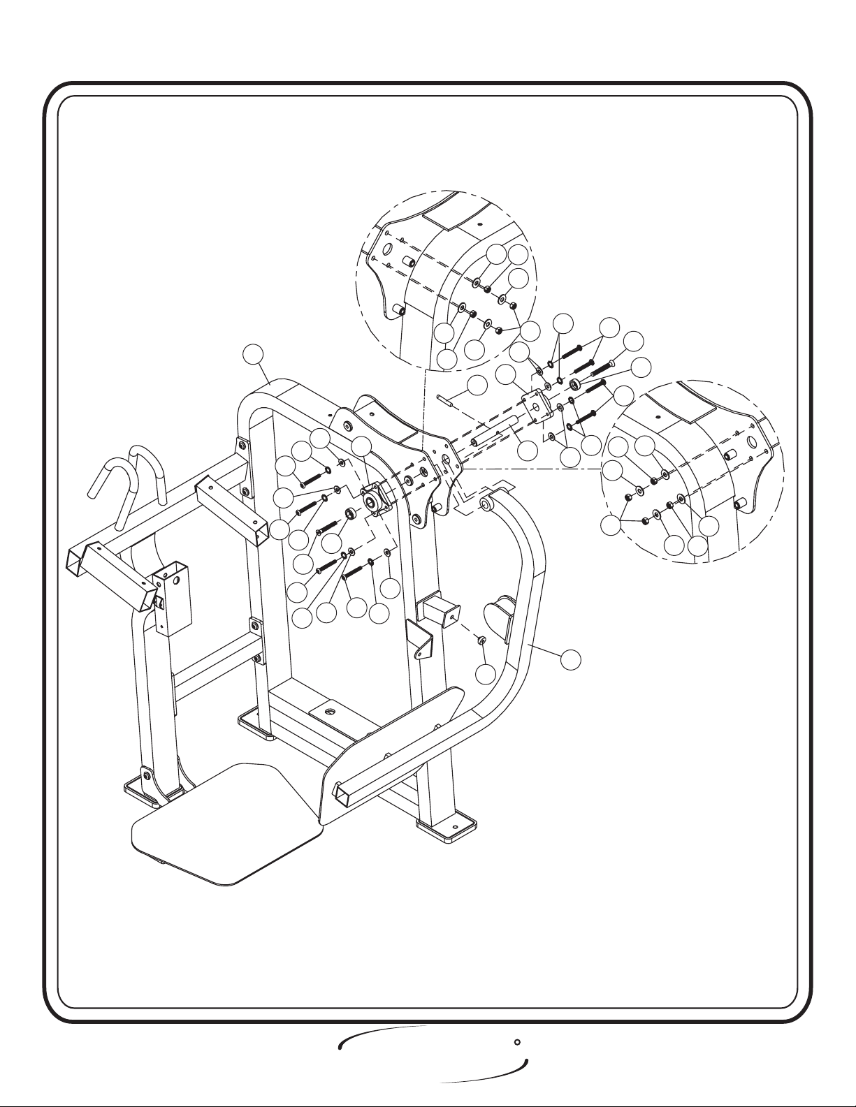
Step 2b
FRAME ASSEMBLY
In this step start by attaching (CM) to (5) and make sure to put zerk
fitting facing down, then attach (9) to (5). Next, slide (16) through one
(CM) then through (9) and through another (CM). Then secure (16) and
(9) with (CN). After (9) is secure to (5) attach (K) to both ends of (16).
bolts only, they will be tightened later.Hand Tighten
Part Descriptions
5 - Weight Cage Assy.
9 - Pivoting Foot Plate Assy.
15 - Aluminum Cap
16 - Shaft
Hardware Descriptions
B - 3/8-16 x 1 1/4” Button Head Screw
K - 3/8-16 x 1” Flat Head Cap Screw
AC - 3/8” Internal Lock Washer
AH - 3/8” Flat Washer
AJ - 3/8” Flat Washer
BA - 3/8” Lock Nut
CC - Plug Bumper
CM - Flange Bearing
CN - 3/8” x 2” Spiral Roll Pin
Page 7
HOIST
FITNESS SYSTEMS
R
2412 Assembly
ASSEMBLY
INSTRUCTIONS
AJ
BA
AJ
AC
CM
AH
BA
16
AH
AJ
5
AH
AH
15
CM
B
AH
AC
AH
B
AC
B
AC
K
B
AC
BA
AJ
CN
CC
B
K
15
B
AC
9
AJ
BA
BA
AJ
AJ
AJ
BA
HOIST
FITNESS SYSTEMS
R
Page - 82412 Assembly

ASSEMBLY
INSTRUCTIONS
Step 2c
FRAME ASSEMBLY
In this step start by pressing two of the (21) into (5). Take two of the
(20) and place them over the two holes in the bottom of (5). Now slide
two of the (17) into the holes. Make sure to lube (17) with Spindle Oil.
Next slide 15 of the (19)and one (18) onto (19). Make sure (19) and (17)
are sitting level. Next, secure (2) to(18) then attach two of the (23) to (2)
and (5). Slide on three of the (24) on either (2) or (5). Then
tighten
Part Descriptions
2 - Center RH BRK (Add-On)
5 - Weight Cage Assy.
17 - Guide Rod
18 - 8.6 lbs. Top Plate
19 - 20 lbs. Intermediate Weight
20 - Weight Bumper
21 - Guide Rod Bushing
22 - Weight Selector Pin
23 - Add On Weight
24 - 5 lbs. Add On Weight
39 - Add On Weight Bushing
bolts including all previously hand tightened bolts.
Hardware Descriptions
C - 3/8-16 x 2 3/4” Button Head Screw
D - 5/16-18 x 1” Button Head Screw
E - 3/8-16 x 1” Button Head Screw
F - 3/8-16 x 1” Button Head Screw
AB - 3/8” Split Washer
AC - 3/8” Internal Lock Washer
AD - 3/8” Internal Lock Washer
AE - 5/16” Internal Lock Washer
AH - 3/8” Flat Washer
AJ - 3/8” Flat Washer
AK - 5/16” Flat Washer
Wrench
Page 9
CA - Selector Pin Lanyard
CE - Guide Bearing
CF - Guide Bearing
HOIST
FITNESS SYSTEMS
R
2412 Assembly
ASSEMBLY
INSTRUCTIONS
SEE PAGE 12 FOR TOP WEIGHT & STEM
ASSEMBLY
39
39
CF
C
C
233923
AB
AJ
AK
AE
D
5
AB
AJ
24
AC
E
AE
22
AH
CA
2
23
20
17
21
CE
18
19
20
17
21
39
AJ
AD
F
HOIST
FITNESS SYSTEMS
R
Page - 102412 Assembly

ASSEMBLY
INSTRUCTIONS
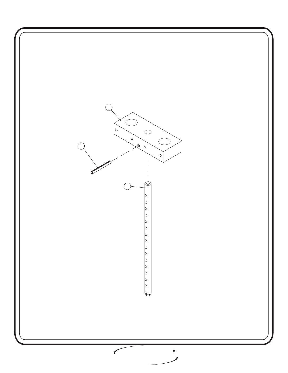
Step 2d
FRAME ASSEMBLY
Slide (25) up into (18) and secure with (CD). bolts.Wrench tighten
Part Descriptions
18 - 8.6 lbs. Top Plate
25 - Stem (16) Holes
Hardware Descriptions
CD - 7/16” x 3” Open Roll Pin
Page 11
HOIST
FITNESS SYSTEMS
R
2412 Assembly
CD
ASSEMBLY
INSTRUCTIONS
18
25
HOIST
FITNESS SYSTEMS
R
Page - 122412 Assembly
 Loading...