

Hoist Fitness CL-2408 User Manual
HOIST
FITNESS SYSTEMS
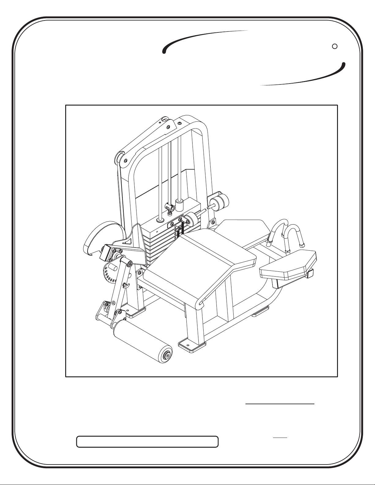
CL-2408
R
Note: Both Serial Number and Model Number are Required when Ordering Parts
RECORD SERIAL NUMBER HERE
OWNERS MANUAL
August 2000
Customer Service
(800) 548-5438
(619) 578-7676
Fa x
(619) 578-9558

ASSEMBLY
INSTRUCTIONS
CONTENTS
INSTRUCTIONS (Step 1) .............................................................
FRAME ASSEMBLY (Step 2) ........................................................
PARTS LISTING ............................................................................
HARDWARE LISTING ..................................................................
BOLT SIZING CHART ..................................................................
WASHER SIZING CHART ............................................................
WEIGHT RATIOS .........................................................................
WEIGHT TRAINING TIPS ...........................................................
WEIGHT TRAINING EXERCISE LOG ......................................
2
4
21
22
24
25
26
28
30
DECAL PLACEMENTS .................................................................
GENERAL MAINTENANCE INFORMATION............................
LIMITED WARRANTY ..................................................................
R
HOIST
Page - 1 2408 Assembly
FITNESS SYSTEMS
32
37
40

ASSEMBLY
INSTRUCTIONS
Step 1
INSTRUCTIONS
Before beginning assembly please take the time to read the
instructions thoroughly. Please use the catalog in this manual to
make sure that all parts have been included in your shipment.
When ordering use the part number and description from the
catalog.
Use only Hoist replacement parts when servicing. Failure
to do so will void your warranty and could result in personal
injury.
Hoist equipment is designed to provide the smoothest, most
effective exercise motion possible. After assembly, you should
check all functions to ensure correct operation. If you
experience problems, first recheck the assembly instructions to
locate any possible errors made during assembly. If you are
unable to correct the problem, call your authorized Hoist dealer.
Be sure to have your serial number and this catalog when calling.
When all parts have been accounted for, continue on to Step 2.
TOOLS REQUIRED
Standard Allen Wrench Set
(2.5mm, 3/32” - 5/16”)
Crescent Wrench
Belt Tensioning Wrench
(Hoist Tool SM374)
Rubber Mallet
Tape Measure
R
HOIST
FITNESS SYSTEMS
Page - 22408 Assembly

ASSEMBLY
INSTRUCTIONS
R
HOIST
Page - 3 2408 Assembly
FITNESS SYSTEMS
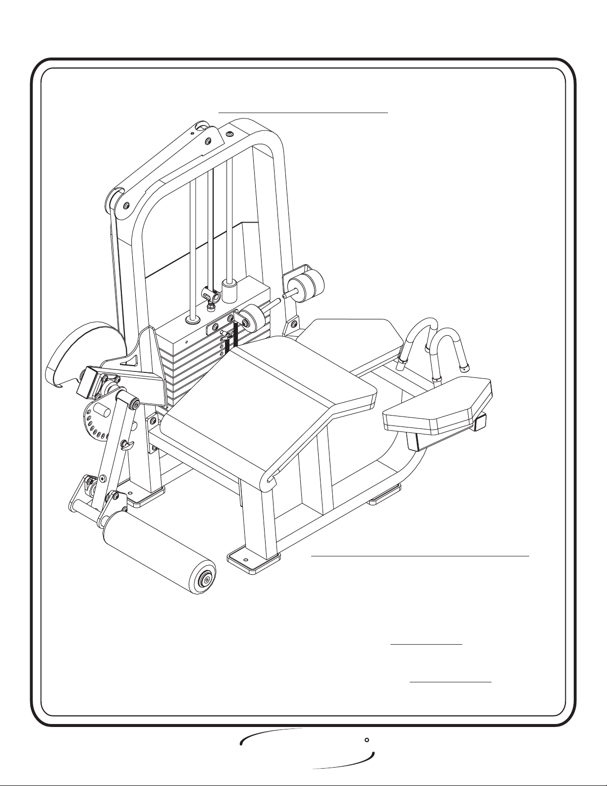
ASSEMBLY
INSTRUCTIONS
Step 2
FRAME ASSEMBLY
FACTORY INSTALLATION INSTRUCTION ONLY
1. ALL THREADED HOLES SHOULD BE TAPPED,
EXCEPT INSERTS.
2. ALL CALLED OUT INSERTS MUST BE INSTALLED BEFORE
ANY ASSEMBLY.
3. PUT A DROP OF ON BOLTS IF
NECESSARY.
4. IF NECESSARY APPLY TO ALL
BEARINGS.
HOIST
FITNESS SYSTEMS
BLUE LOCTITE 242
GREEN LOCTITE 680
R
Page - 42408 Assembly

ASSEMBLY
INSTRUCTIONS
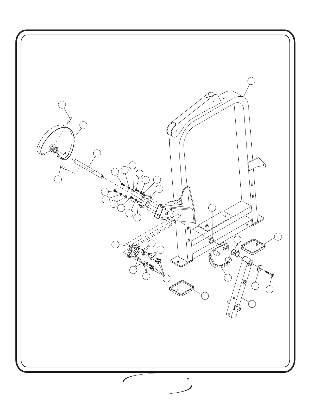
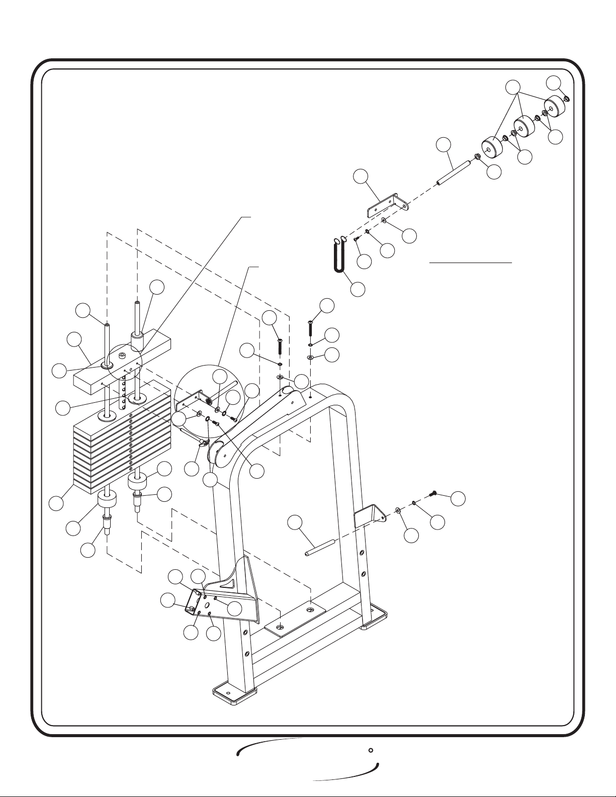
Step 2a
FRAME ASSEMBLY
In this step attach two Flange Bearings to the Weight Cage. Make sure to
put zerk fitting facing down on Flange Bearings. Next attach the 1” Dia.
CRS to the Cam Assembly (Large). Slide the other side of the 1” Dia. CRS
through the Flange Bearings and the Weight Cage. Attach the Range of
Motion, Extension Tube Assembly, and a Red Iodized Aluminum Cap to
the 1” Dia. CRS. bolts only, they will be tightened later.
Hand Tighten
Lift Machine to position Rubber Feet.
Part Descriptions
2 - Range of Motion
4 - Extension Tube Assembly
6 - Cam Assembly (Large)
7 - Weight Cage
12 - 1” Dia. CRS
23 - Rubber Feet
34 - Red Iodized Aluminum Cap
36 - Black Plastic Ring
Hardware Descriptions
D - 3/8” x 1 1/4” Flat Head Screw
E - 3/8” x 1 1/4” Button Head Screw
T - 3/8” Lock Washer (black)
W - 3/8” x 2 Open Roll Pin
X - 1” Dia. X .8mm Shims
AH - Flange Bearing
BE - 3/8” Flat Washer
R
HOIST
Page - 5 2408 Assembly
FITNESS SYSTEMS
ASSEMBLY
INSTRUCTIONS
7
W
6
12
BE
T
E
W
E
BE
T
E
T
BE
E
T
BE
AH
BE
AH
36
BE
T
T
E
23
X
2
34
4
23
D
SEE PRE-ASSEMBLED PARTS ON PAGE 20
BEFORE ASSEMBLED MACHINE.
HOIST
FITNESS SYSTEMS
R
Page - 62408 Assembly

ASSEMBLY
INSTRUCTIONS
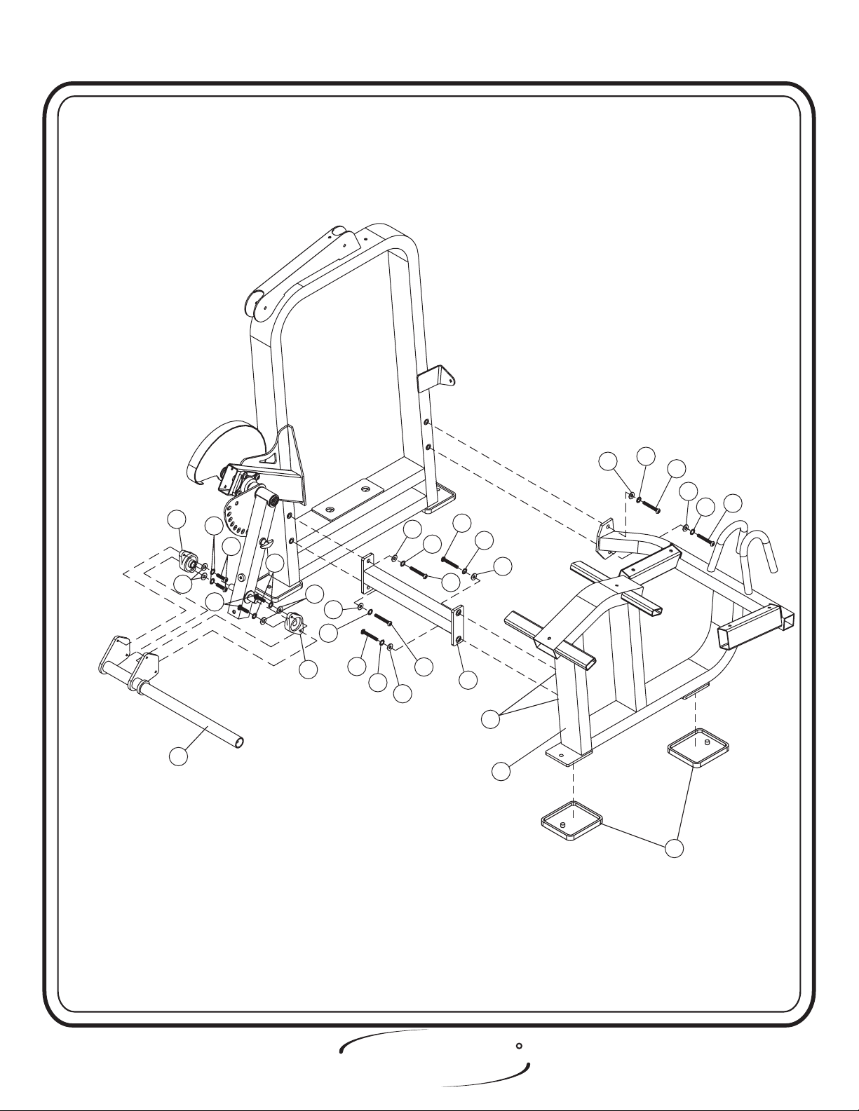
Step 2b
FRAME ASSEMBLY
In this step, start by attaching the Cross Tube Assembly to the Weight Cage,
then attach the Seated frame to the Cross Tube Assembly and the Weight Cage.
Next insert the Bearings (BF) in the Extension Tube Assembly then align the Shin
bar Assembly to the Bearings and secure. Make sure to put zerk fitting facing
down. bolts only, they will be tightened later.Hand Tighten
position Rubber Feet.
Part Descriptions
5 - Shin Bar Assembly
8 - Seated Frame Assembly
9 - Cross Tube Assembly
13 - Shaft
23 - Rubber Foot Pad
Lift Machine to
Hardware Descriptions
A - 1/2” x 1 1/2” Button Head Screw
H - 3/8-16” x 1” Button Head Screw
N - 1/2” Lock Washer
P - 1/2” Flat Washer
T - 3/8” Internal Lock Washer
AJ - 1/2” Insert
AR - Flange Bearing (014-0008004)
BE - 3/8” Flat Washer
R
HOIST
Page - 7 2408 Assembly
FITNESS SYSTEMS
AR
BE
AR
ASSEMBLY
INSTRUCTIONS
N
P
T
H
T
BE
P
N
P
A
N
N
P
A
A
P
A
N
AR
5
A
N
HOIST
FITNESS SYSTEMS
A
9
P
AJ
1/2” INSERTS ARE BEHIND
8
23
R
Page - 82408 Assembly

ASSEMBLY
INSTRUCTIONS
Step 2c
FRAME ASSEMBLY
In this step start by pressing two Guide Rod Bushings into the
Weight Cage. Take the two 3” x 1” I.D. Bumpers and place them over the
two holes in the bottom of the Now slide the Guide Rods into
Weight Cage.
the holes. Make sure to lube the Guide Rods with Spindle Oil. Next slide
on ten(10) 20 LBS Intermediate Weight Plates and one(1) 15 LBS
Aluminum Top Plate onto the Guide Rods, and bolt into place. Make sure
the Weight Stack and its Guide Rods are sitting level. Next, attach the
5/8” Dia. x 6 13/32” Rod to the Center RH BRK ( Add-On). Secure the
Center RH BRK (Add-On) to the . Slide on
15 LBS Aluminum Top Plate
three 5 LBS. Add-On Weights and attach the 5/8” Dia. x 6 13/32” Rod to
the . Attach bigger end of the Selector Pin Lanyard to the
Weight Cage
Center RH BRK ( Add-On)
, and the other end to the Weight Selector Pin.
Then bolts including all previously hand tightened boltsWrench tighten .
Hardware Descriptions
H - 3/8” x 1 Button Head Screw
Part Descriptions
3 - Center RH BRK (Add-On)
10 - Guide Rod
15 - 5/8” Dia. x 6 13/32” (Add-On)
Rod
19 - 15 lbs Aluminum Top Plate
32 - 11 Plate Selector Stem
33 - 20 lbs Intermediate Weight
37 - Add On Weight Bushing
G - 5/16” x 1” Button Head Cap Screw
J - 3/8” x 2 3/4” Button Head Cap Screw
Q - 3/8” Flat Washer
R - 3/8” Lock Washer
V - 5/16” Flat Washer
T - 3/8” Internal Lock Washer
AK - Guide Rod Bushing
AL - 3” x 1” I.D. x 1 1/2” THK Bumper
AM - Guide Bearing
AN - Guide Bearing
AP - Selector Pin Lanyard
AT - Weight Selector Pin
AU - 5 lbs Add-On Weight
AW - Insert
BB - 3/8” x 1” Button Head Screw (white zinc)
BC - 3/8” Split Washer
BE - 3/8” Flat Washer
BJ - 5/16” Internal Lock Washer
R
HOIST
Page - 9 2408 Assembly
FITNESS SYSTEMS
ASSEMBLY
INSTRUCTIONS
AN
32
19
10
AM
AU
15
3
FOR ASSEMBLY INSTRUCTION
FOR ASSEMBLY INSTRUCTION
PAGE 18
SEE PAGE 18
SEE
BE
T
FOR CLARITY SEE A-1FOR CLARITY SEE A-1
J
J
BC
BC
V
G
BJ
V
Q
Q
H
AP
A-1
37
37
37
37
AL
AT
BJ
33
AL
AK
AK
AW
AW
AW
AW
AW
2408 Assembly Page - 10
G
AW
HOIST
FITNESS SYSTEMS
15
BB
R
Q
R

ASSEMBLY
INSTRUCTIONS
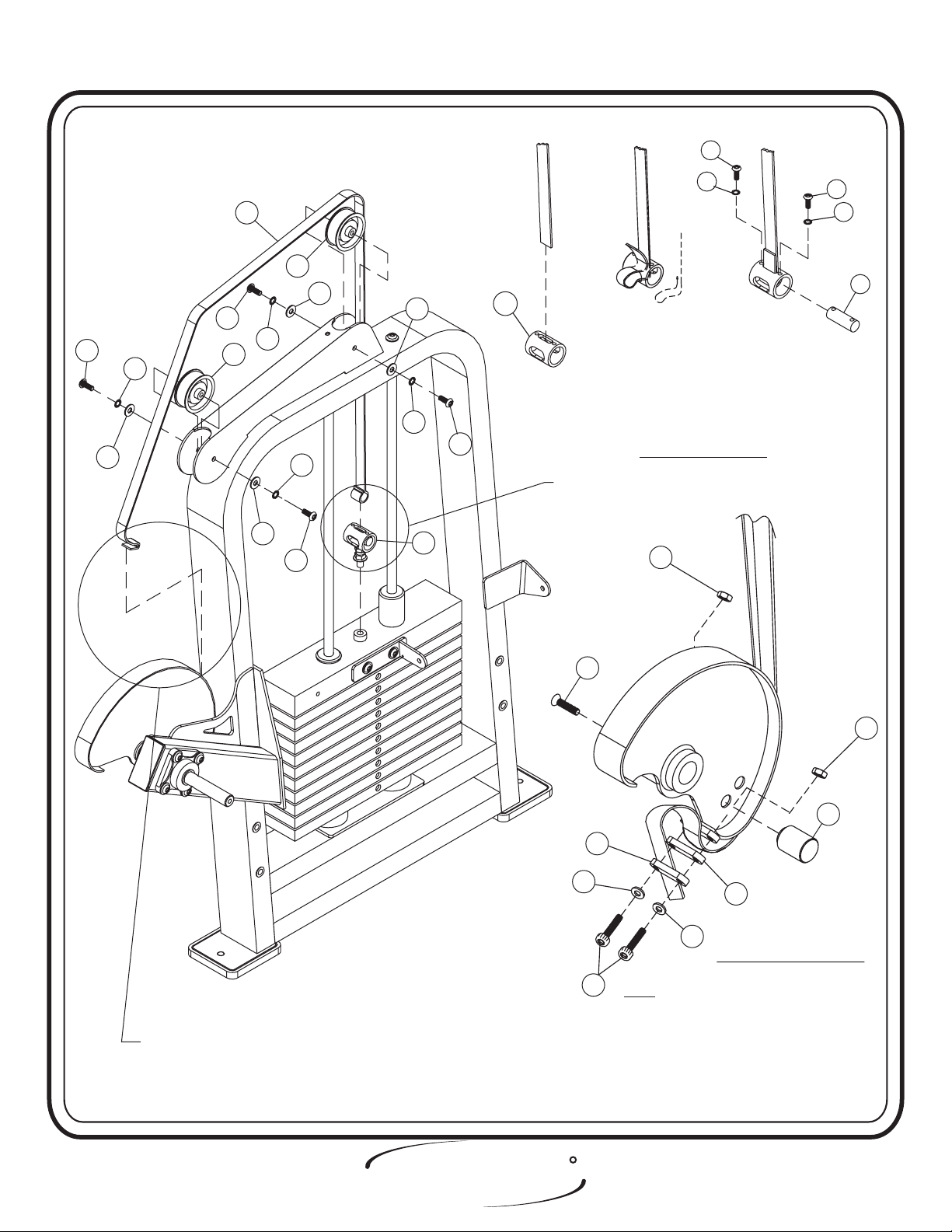
Step 2d
FRAME ASSEMBLY
In this step start by attaching the Belt Assembly to the Weight
Assembly(prior to attaching the Cam Belt). Next slide the Cam Belt
through the Roller Bracket on the top of the Weight Cage. Then use a
Seat Clamp On tool to secure the two 3 1/4” Pulleys to the
under the Cam Belt.
Slide the Cam Belt into the top slot of 1 5/8” Dia. x 2
Weight Cage
1/16” Lg. Dom. (Fig. 1) Loop the end of the Cam Belt and feed it back up
through the slot, keeping the loop open. (Fig 2) Next, slide the 3/4” x 2
1/16 CRS through the Cam belt and line up the holes, then secure to the 1
5/8” Dia. X 2 1/16” Lg. Dom.(Fig. 3). ttaching the Cam Stopper to the
A
Cam Assembly. Next, attach the belt by bringing it around the Cam and in
between the Belt Clamps. Then wrap the cam belt down and around the
Belt Clamps and above another Belt clamp and secure all the Clamps
together.
Part Descriptions
1 - Belt Assembly
14 - 3/4” x 2 1/16” CRS
16 - Clamp
20 - Cam Belt 74” x 15/16” x 1/8”
22 - 1 1/2” Dia. Delrin Stop
35 - 1 5/8” x 2 1/16” lg DOM
bolts.Wrench tighten
Hardware Descriptions
C - 1/2” x 1” Flat Head Cap Screw
F - 1/4” x 1” Button Head Screw
M - 3/8” x 3/4” Button Head Screw
Q - 3/8” Flat Washer
R - 3/8” Lock Washer
S - 1/4” Lock Washer
Z - 1/4-20 x 1 1/2” Socket Head Screw
AS - 3 1/4” Pulley
AY - 1/4” Lock Nut
R
HOIST
Page - 11 2408 Assembly
FITNESS SYSTEMS
ASSEMBLY
INSTRUCTIONS
FIGURE 1FIGURE 1 FIGURE 3FIGURE 3FIGURE 2FIGURE 2
F
S
20
AS
Q
M
M
R
Q
R
AS
R
Q
M
Q
R
1
35
M
FOR BELT ASSEMBLY SEE SX145 B-1FOR BELT ASSEMBLY SEE SX145 B-1
B-1
AY
F
S
14
FOR BELT ASSEMBLY SEE B-2FOR BELT ASSEMBLY SEE B-2
C
16
S
Z
NOTE: 1. BELT SMOOTH SIDE DOWN, ALWAYS
FOR TWO TOP PULLEYS AND CAM.
SMOOTH SIDE TO WRAP AROUND
BELT RETAINER SHAFT
2. WHEN TIGHTENING THE CLAMPS
(44) TO THE BELT DO NOT EXCEED
60 IN. LBS.
3. INSURE DELRIN STOP IS SECURED IN
HOLE CLOSEST TO BELT CLAMP
16
S
B-2
AY
22
R
HOIST
2408 Assembly Page - 12
FITNESS SYSTEMS
 Loading...