

Hoist Fitness CL-2407 User Manual
HOIST
FITNESS SYSTEMS
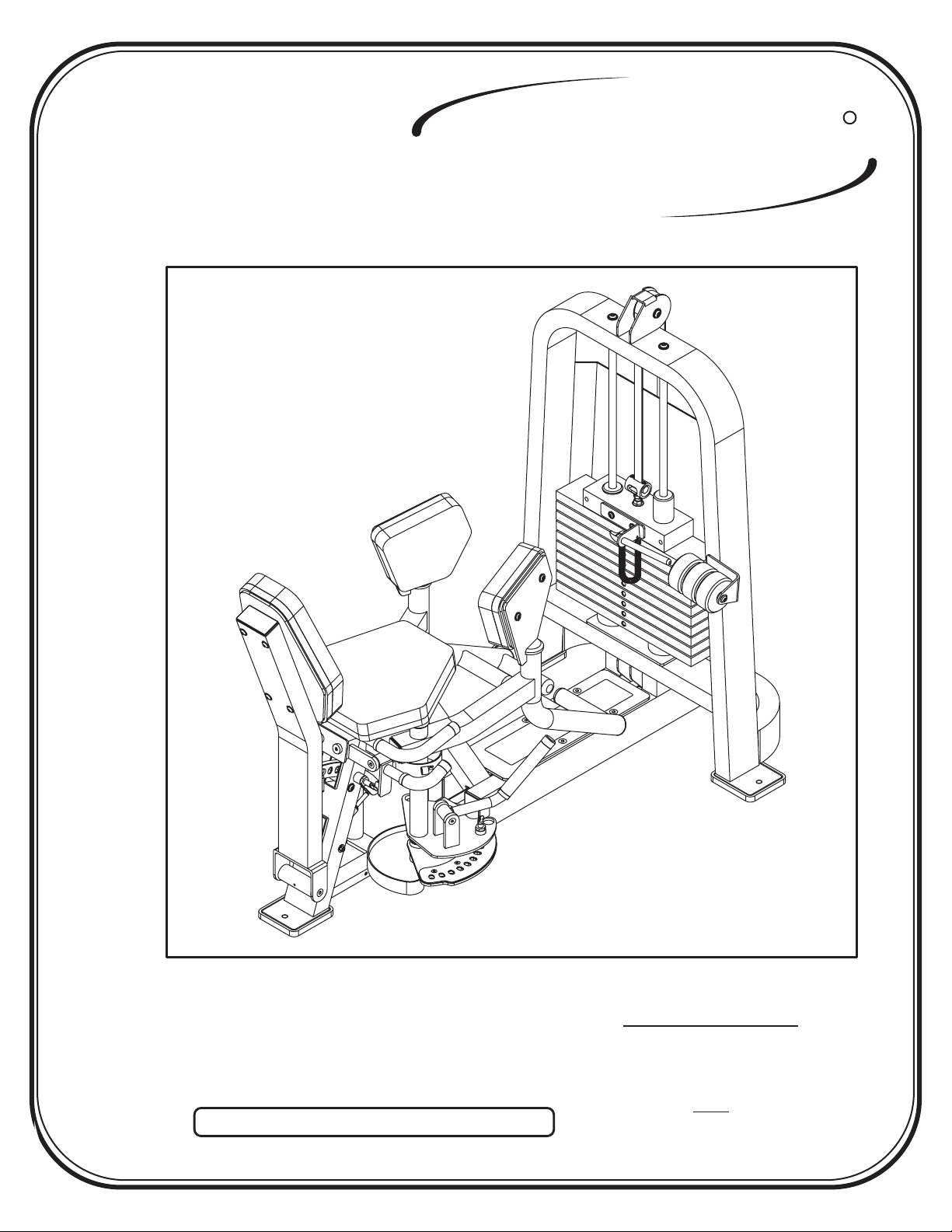
CL-2407
R
Note: Both Serial Number and Model Number are Required when Ordering Parts
RECORD SERIAL NUMBER HERE
OWNERS MANUAL
June 2000
Customer Service
(800) 548-5438
(619) 578-7676
Fa x
(619) 578-9558

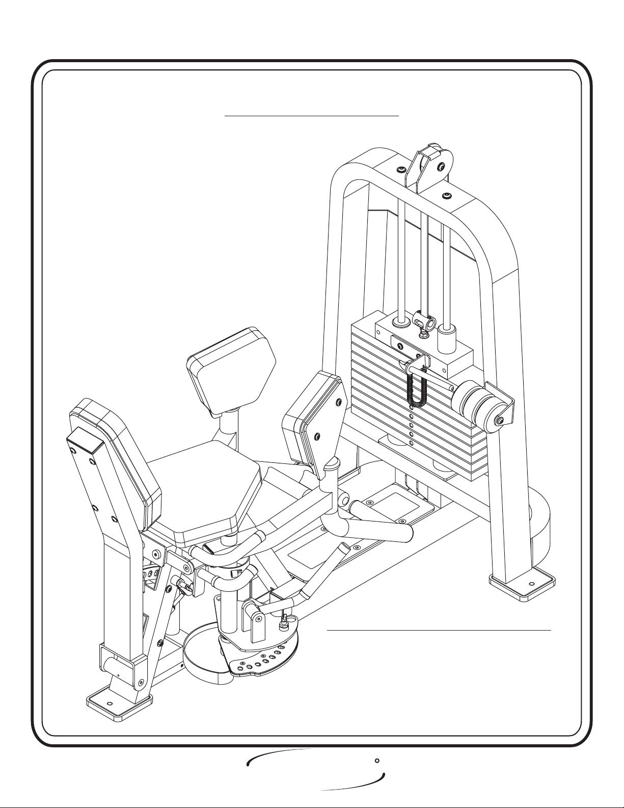
ASSEMBLY
INSTRUCTIONS
CONTENTS
INSTRUCTIONS (Step 1) .............................................................
FRAME ASSEMBLY (Step 2) ........................................................
PARTS LISTING ............................................................................
HARDWARE LISTING ..................................................................
BOLT SIZING CHART ..................................................................
WASHER SIZING CHART ............................................................
WEIGHT RATIOS .........................................................................
WEIGHT TRAINING TIPS ...........................................................
WEIGHT TRAINING EXERCISE LOG .......................................
2
4
23
24
25
26
27
29
31
Page 1
DECAL REFERENCE ...................................................................
GENERAL MAINTENANCE .........................................................
LIMITED WARRANTY ..................................................................
R
HOIST
FITNESS SYSTEMS
2407 Assembly
33
39
42

ASSEMBLY
INSTRUCTIONS
Step 1
INSTRUCTIONS
Before beginning assembly please take the time to read the
instructions thoroughly. Please use the catalog in this manual to
make sure that all parts have been included in your shipment.
When ordering use the part number and description from the
catalog.
Use only Hoist replacement parts when servicing. Failure
to do so will void your warranty and could result in personal
injury.
Hoist equipment is designed to provide the smoothest, most
effective exercise motion possible. After assembly you should
check all functions to ensure correct operation. If you
experience problems, first recheck the assembly instructions to
locate any possible errors made during assembly. If you are
unable to correct the problem, call your authorized Hoist dealer.
Be sure to have your serial number and this catalog when calling.
When all parts have been accounted for continue on to Step 2.
TOOLS REQUIRED
Standard Allen Wrench Set
(2.5mm, 3/32” - 5/16”)
Crescent Wrench
Belt Tensioning Wrench
(Hoist Tool SM374)
Rubber Mallet
Tape Measure
R
HOIST
FITNESS SYSTEMS
Page - 22407 Assembly

ASSEMBLY
INSTRUCTIONS
Page 3
HOIST
FITNESS SYSTEMS
R
2407 Assembly
ASSEMBLY
INSTRUCTIONS
Step 2
FRAME ASSEMBLY
FACTORY INSTALLATION INSTRUCTION ONLY
1. ALL THREADED HOLES SHOULD BE TAPPED,
2. ALL CALLED INSERTS MUST BE INSTALLED BEFORE ANY
HOIST
FITNESS SYSTEMS
EXCEPT INSERTS.
ASSEMBLY.
R
Page - 42407 Assembly
ASSEMBLY
INSTRUCTIONS
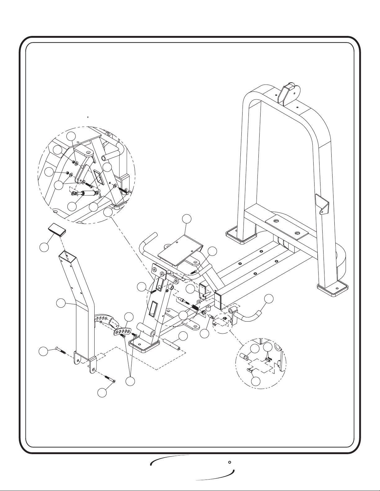
Step 2a
FRAME ASSEMBLY
( ) Insert (CG) and (CP) into (1) and (2). Attach
Factory Installation
(1) to (2). Then insert (6) into (1). Next attach (CA) and (4) to the rear
of (1). bolts only, they will be tightened later. Lift machine
Hand tighten
to position (3).
Part Descriptions
1 - Seated Assembly
2 - Weight Cage
3 - Rubber Foot Pad
4 - 2”x 4” End Caps
6 - Shaft
(1/2”Dia. x 1.240 LG.)
(VH)
Hardware Descriptions
A - 1/2”-13 x 1 1/2” Button Head Screw
B - 5/16”-18 x 2” Button Head Screw
AA - 1/2” Lock Washer
AB - 1/2” Flat Washer
AM - 5/16” Flat Washer
CA - Plug Bumper
(White Zinc)
(White Zinc)
(White Zinc)
(White Zinc)
(White Zinc)
Page 5
CG - Insert 1/2”
CP - Insert 3/8”
CT - 3/4” Olite
HOIST
FITNESS SYSTEMS
R
2407 Assembly

ASSEMBLY
INSTRUCTIONS
FACTORY INSTALL 4 THREADED
INSERTS (CG) TO WEIGHT CAGE.
2
3
AB
AA
A
CP
3
AB
AA
AB
A
AB
AA
AA
A
A
3
4
B
1
CA
4
6
AM
B
AM
CT
HOIST
FITNESS SYSTEMS
CT
3
R
Page - 62407 Assembly
ASSEMBLY
INSTRUCTIONS
Step 2b
FRAME ASSEMBLY
In this step, you will attach (30) and (7) to (8). Mount (CB) to (1) and (8)
before attaching (9) and (8) to the bottom of (1). Next attach (5), (11), (44),
(CH), and (10) to (1). bolts only, they will be tightened later.Hand Tighten
Part Descriptions
1 - Seat Assembly
5 - Shaft
7 - 2”x 4” End Cap
8 - Back Adjuster Assembly
9 - Shaft
10 - Back Adjuster Assembly
11 - Pull Pin
30 - Adjustable Plate
44 - Pull Pin to Chain Link Connector
(1/2 Dia. x 1.240 LG.)
(HH)
(3/4”Dia. x 4 27/32 LG.)
(Long)
Hardware Descriptions
D - 3/8”-16 x 1/2” Flat Head Cap Screw
E - 3/8”-16 x 3/4” Flat Head Cap Screw
S - 5/16”-18 x 1 1/4” Button Head Screw
U - 5/16”-18 x 4 1/2” Hex Head Screw
AE - 3/8” Flat Washer
AM - 5/16” Flat Washer
BD - 5/16” Lock Nut
CB - Gas Spring
CH - Master Chain Link
(White Zinc)
(White Zinc)
(White Zinc)
(White Zinc)
(White Zinc)
(White Zinc)
(White Zinc)
Page 7
HOIST
FITNESS SYSTEMS
R
2407 Assembly
*DETAIL OF SHOCK INSTALLATION
*DETAIL OF SHOCK INSTALLATION
ROTATED 180 FOR CLARITY
ROTATED
BD
180 FOR CLARITY
AM
ASSEMBLY
INSTRUCTIONS
AM
S
U
1
E
E
30
11
9
5
10
44
BD
AM
CB
7
8
CH
E
(GRIND TO FLUSH)(GRIND TO FLUSH)
D
E
R
HOIST
FITNESS SYSTEMS
44
CH
Page - 82407 Assembly
ASSEMBLY
INSTRUCTIONS
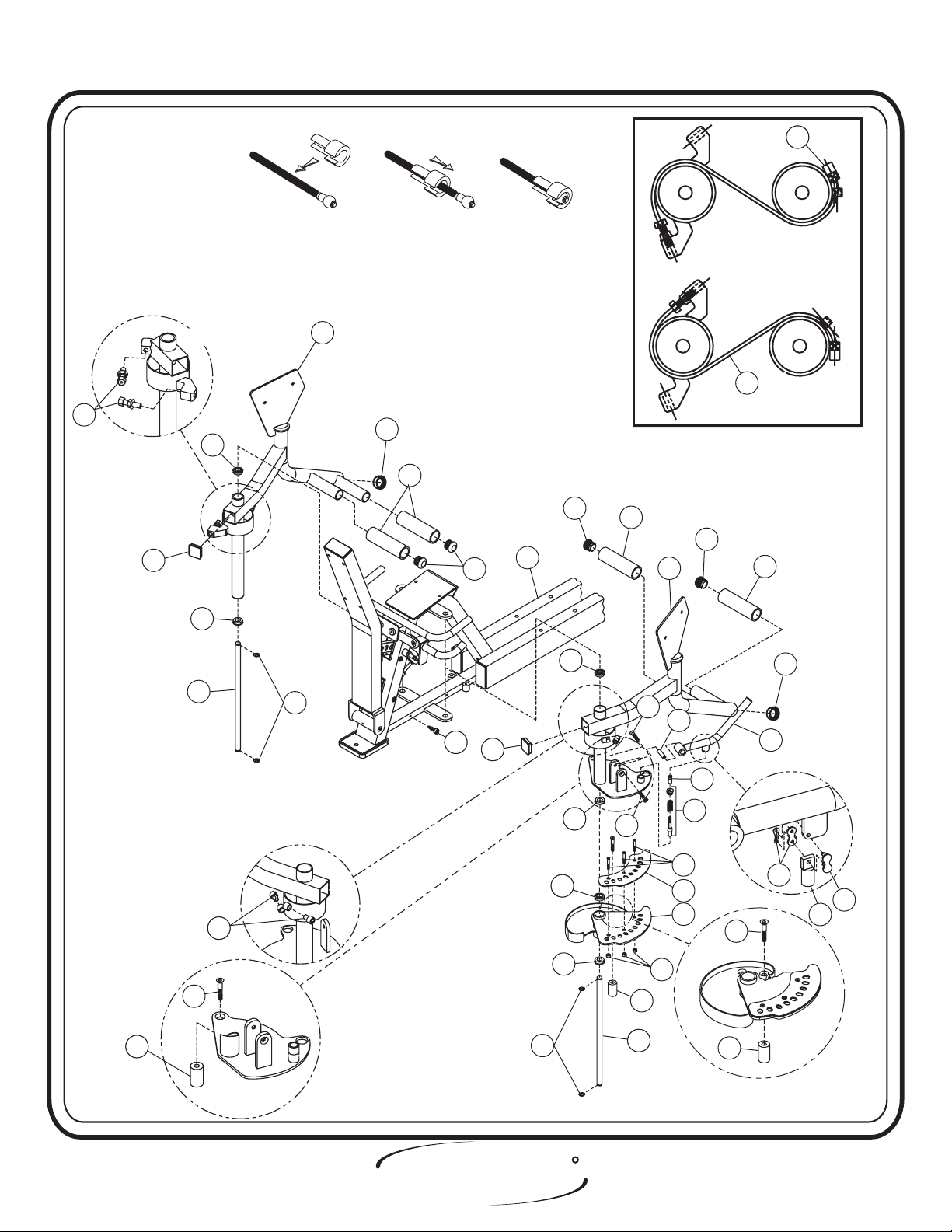
Step 2c
FRAME ASSEMBLY
In this step, you will need to install (14) and (13) to both (15) and (16).
Next insert (CC) into (15), (16) and (21). Now align (15) with (1), securing it
with (17) and (CJ). Next attach the (45) to (21). Next align (16) and (21) to (1),
securing them with (17) and (CJ). Attach (5), (20), (18), (44), and (CH) to (16).
Next attach (41) and (40) to both (15) and (16). Finish off the assembly by
attaching (19) to (21) and (CK) to (1). all bolts.Wrench tighten
Part Descriptions
1 - Seat Assembly
5 - Shaft
13 - 2”x 2” End Cap
14 - End Cap Plug
15 - Left Inner Thigh Assembly
16 - Right Inner Thigh Assembly
17 - Arm Axle
18 - Pull Pin
19 - Cam Stopper
20 - Adjuster Handle Assembly
21 - ROM/CAM Assembly
40 - Quick Release Cable Locks
41 - Arm Cable
44 - Pull Pin to Chain Link Connector
45 - Adjustable Plate
(1/2”Dia. X 1.938” LG.)
(3/4”Dia. X 19.16” LG.)
(Short)
Hardware Descriptions
E - 3/8”-16 x 3/4” Flat Head Cap Screw
G - 1/2”-13 x 1” Flat Head Cap Screw
Q - 1/4”-20 x 1” Flat Head Cap Screw
BA - 1/4” Lock Nut (
CC - Bearing
CH - Master Chain Link
CJ - 3/4” Retaining Ring
CK - Adjustable Stop
CQ - 2” Dia. End Cap
CR - Delrin Stop (Long)
CS - 4 3/4” LG Knurled Sleeves
White Zinc)
(White Zinc)
(White Zinc)
(White Zinc)
R
HOIST
Page - 9 2407 Assembly
FITNESS SYSTEMS
ASSEMBLY
INSTRUCTIONS
Step 1 Step 2 Step 3
Quick Release Cable Lock Assembly
15
41
40
40
41
13
13
CC
CC
17
17
CC
4040
CJ
CQ
CS
CK
CK
14
13
13
DETAIL OF CABLE SET-UPDETAIL OF CABLE SET-UP
14
1
CC
CC
CCCC
CC
CC
CS
E
14
16
E
5
44
18
Q
45
21
CS
CQ
20
CH
CH
44
G
4040
CC
G
CJ
R
HOIST
FITNESS SYSTEMS
19
17
17
BA
19
Page - 102407 Assembly
ASSEMBLY
INSTRUCTIONS
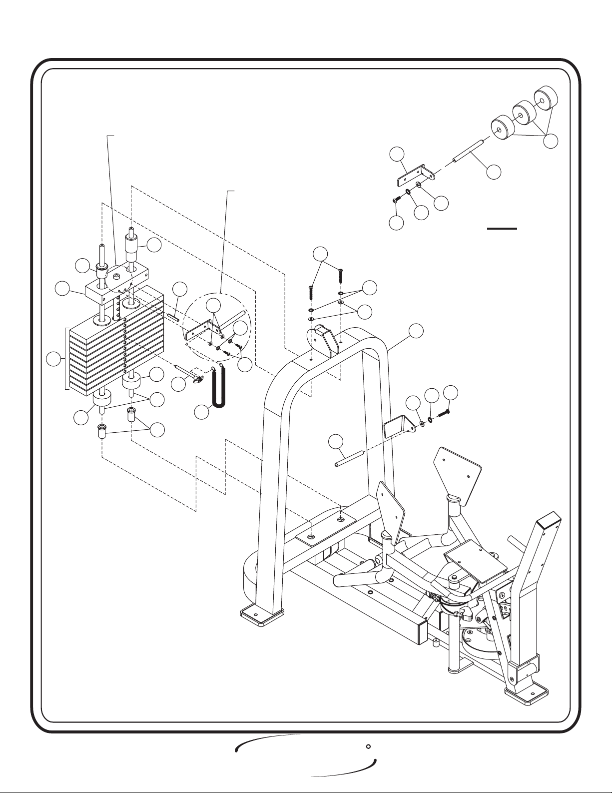
Step 2d
FRAME ASSEMBLY
In this step, start by pressing (29) into (2). Place a (28) over the two
holes in the bottom of (2). Now slide (31) into the holes. Slide (27) and
the (26) onto (31). Make sure (26) and (27) and (31) are sitting level, then
fasten the top of each (31) to (2). Next attach (23) to (22). Secure (22) to
(26), slide on (24) and attach another (23) to the (2). Attach bigger end of
the (CL) to (22), and the other end to (25). Then bolts.Wrench tighten
Part Descriptions
2 - Weight Cage
22 - Center RH (BRK) Assembly
23 - Add On Rods
24 - 5lbs. Add On Weight
25 - Weight Selector Pin
26 - 20lbs. Steel Weight Plate
27 - 20lbs. Intermediate Weight Plates
28 - Weight Bumper
29 - Guide Rod Bushing
31 - Guide Rods
Hardware Descriptions
F - 3/8”-16 x 1” Button Head Screw
H - 3/8”-16 x 1” Button Head Screw
J - 3/8”-16 x 2 3/4” Button Head Screw
K - 5/16”-18 x 1” Button Head Screw
AE - 3/8” Flat Washer
AF - 3/8” Lock Washer
AG - 5/16” Flat Washer
AH - 5/16” Lock Washer
AJ - 3/8” Split Washer
AK - 3/8” Lock Washer
AL - 3/8” Flat Washer
CD - Top Weight Roll Pin
CE - Guide Bearing
CF - Guide Bearing
CL - Selector Pin Lanyard
(White Zinc)
(White Zinc)
(Black Zinc)
(Black Zinc)
(White Zinc)
(Black Zinc)
(Black Zinc)
(Tall)
(Short)
(White Zinc)
(Black Zinc)
(White Zinc)
(Black Zinc)
Page 11
HOIST
FITNESS SYSTEMS
R
2407 Assembly
ASSEMBLY
INSTRUCTIONS
27
26
CF
28
FOR ASSEMBLY INSTRUCTION
SEE PAGE 22
FOR ASSEMBLY SEE A-1
CE
CD
AG
AH
K
28
25
31
CL
29
24
22
23
AK
AL
H
J
AJ
AE
2
F
AF
AE
23
A-1
R
HOIST
2407 Assembly Page - 12
FITNESS SYSTEMS
 Loading...