

Hoist Fitness CL-2403 User Manual
HOIST
FITNESS SYSTEMS
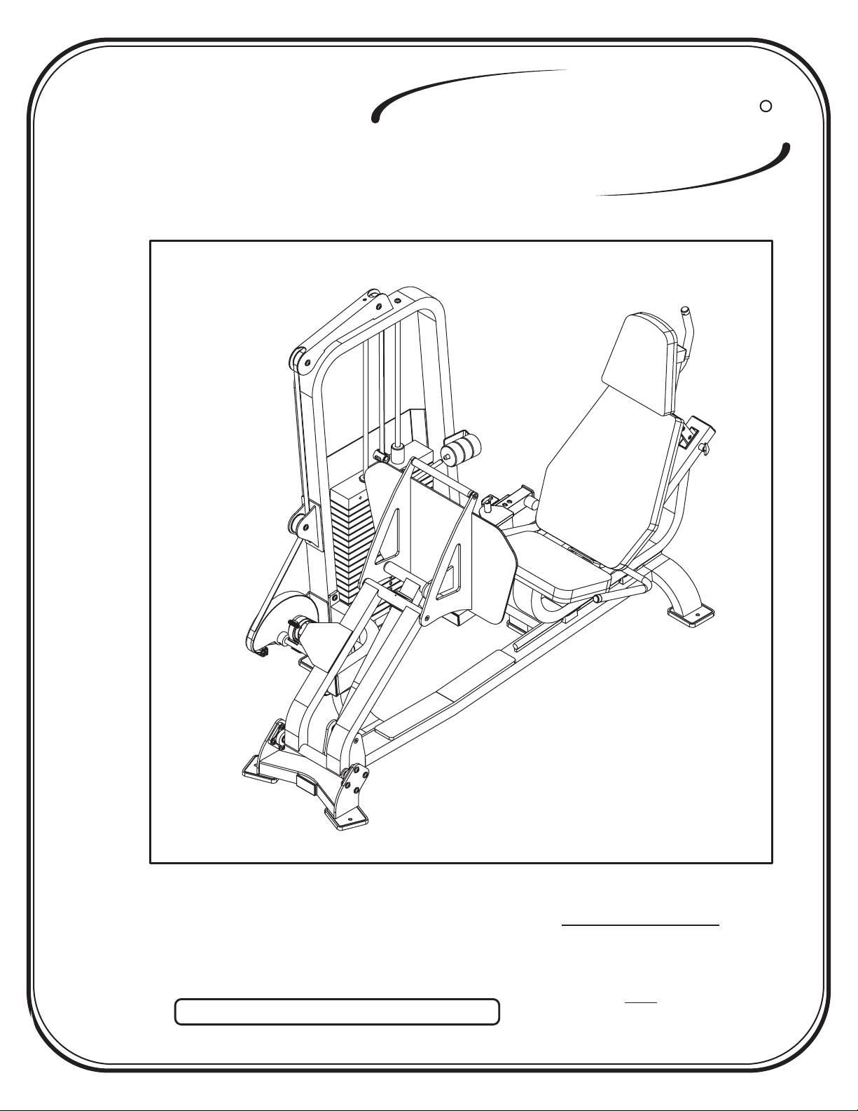
CL-2403
R
Note: Both Serial Number and Model Number are Required when Ordering Parts
RECORD SERIAL NUMBER HERE
OWNERS MANUAL
August 2000
Customer Service
(800) 548-5438
(619) 578-7676
Fa x
(619) 578-9558

ASSEMBLY
INSTRUCTIONS
CONTENTS
INSTRUCTIONS (Step 1) .............................................................
FRAME ASSEMBLY (Step 2) ........................................................
PARTS LISTING ............................................................................
HARDWARE LISTING ..................................................................
BOLT SIZING CHART ..................................................................
WASHER SIZING CHART ............................................................
WEIGHT RATIOS .........................................................................
WEIGHT TRAINING TIPS ...........................................................
WEIGHT TRAINING EXERCISE LOG ........................................
2
4
31
32
34
35
36
38
40
Page 1
DECAL PLACEMENTS ..................................................................
GENERAL MAINTENANCE INFORMATION..............................
LIMITED WARRANTY ..................................................................
R
HOIST
FITNESS SYSTEMS
2403 Assembly
42
47
50

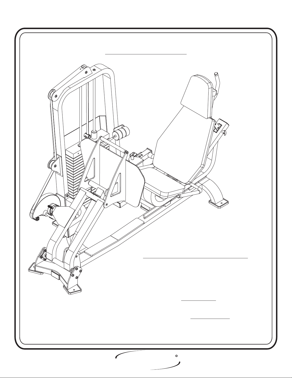
ASSEMBLY
INSTRUCTIONS
Step 1
INSTRUCTIONS
Before beginning assembly please take the time to read the
instructions thoroughly. Please use the catalog in this manual to
make sure that all parts have been included in your shipment.
When ordering use the part number and description from the
catalog.
Use only Hoist replacement parts when servicing. Failure
to do so will void your warranty and could result in personal
injury.
Hoist equipment is designed to provide the smoothest, most
effective exercise motion possible. After assembly, you should
check all functions to ensure correct operation. If you
experience problems, first recheck the assembly instructions to
locate any possible errors made during assembly. If you are
unable to correct the problem, call your authorized Hoist dealer.
Be sure to have your serial number and this catalog when calling.
When all parts have been accounted for, continue on to Step 2.
TOOLS REQUIRED
Standard Allen Wrench Set
(2.5mm, 3/32” - 5/16”)
Crescent Wrench
Belt Tensioning Wrench
(Hoist Tool SM374)
Rubber Mallet
Tape Measure
R
HOIST
FITNESS SYSTEMS
Page - 22403 Assembly

ASSEMBLY
INSTRUCTIONS
Page 3
HOIST
FITNESS SYSTEMS
R
2403 Assembly
ASSEMBLY
INSTRUCTIONS
Step 2
FRAME ASSEMBLY
FACTORY INSTALLATION INSTRUCTION ONLY
1. ALL THREADED HOLES SHOULD BE TAPPED,
EXCEPT INSERTS.
2. ALL CALLED OUT INSERTS MUST BE INSTALLED BEFORE
ANY ASSEMBLY.
3. PUT A DROP OF ON BOLTS IF
NECESSARY.
4. IF NECESSARY APPLY TO ALL
BEARINGS.
HOIST
FITNESS SYSTEMS
BLUE LOCTITE 242
GREEN LOCTITE 680
R
Page - 42403 Assembly

ASSEMBLY
INSTRUCTIONS
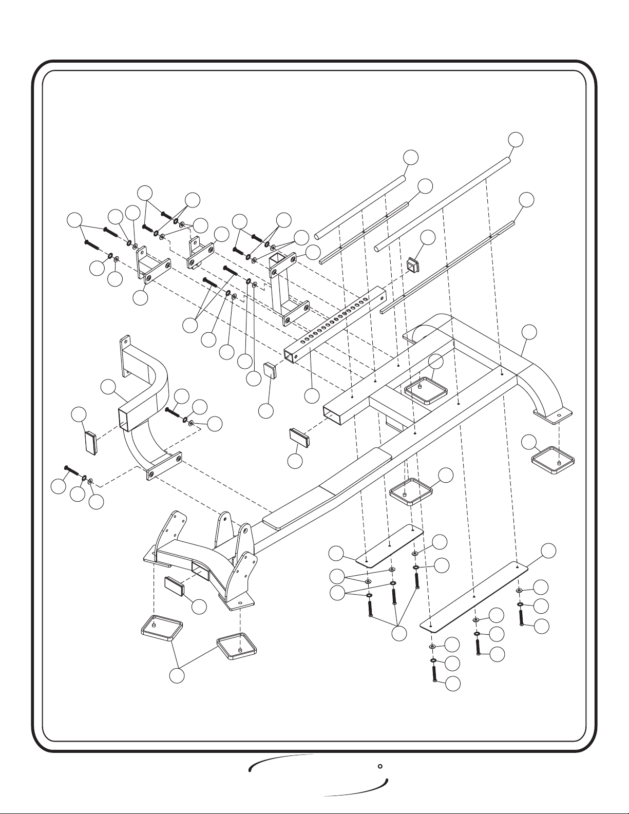
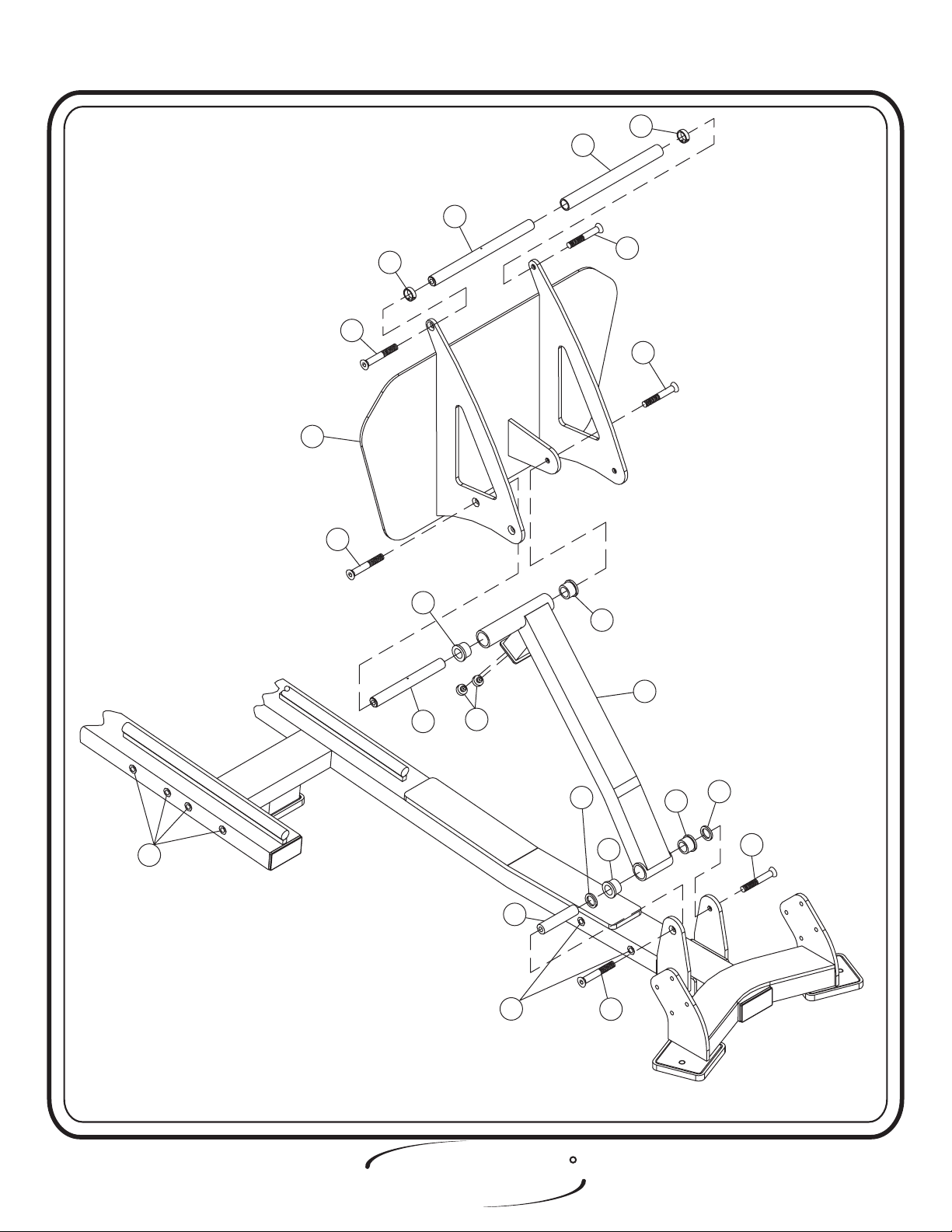
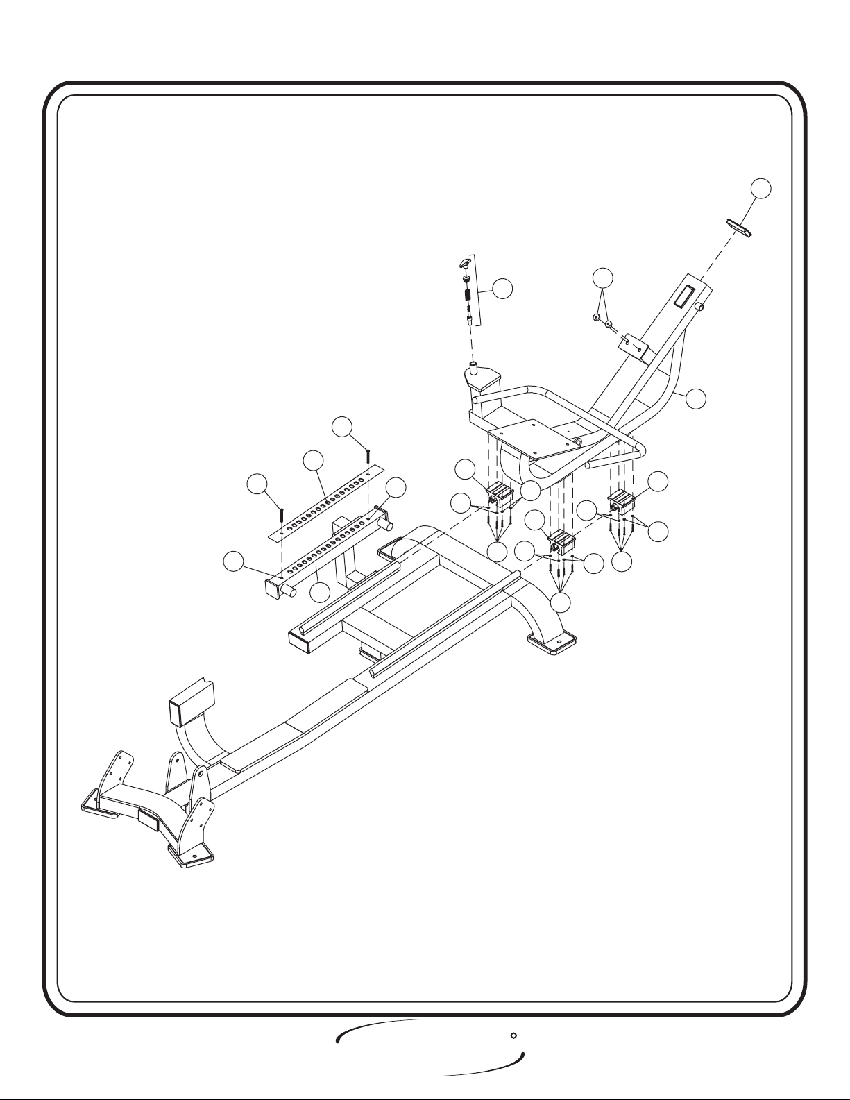
Step 2a
FRAME ASSEMBLY
Start assembling your CL-2403 by attaching the Seat Adjustment, Front
Mount Lower and the Seat Adjustment Rear Mount, to the Running Base
Assembly. Next attach the Seat Slide Adjuster to the Seat Adjustment,
Rear Mount. Now attach the Seat Adjuster, Front Mount Top to the Seat
Slide Adjuster. Attach the Front Attachment Assembly to the Running
Base Assembly. Now attach the Short Plate, Long Plate, Short Shaft,
Long Shaft, Short Stand-Off Rail, and the Long Stand-Off Rail to the
Front Attachment Assembly. bolts only, they will be
Hand Tighten
tightened later. Lift Machine to position Rubber Feet and insert all end
caps.
Part Descriptions
2 - Running Base Assembly
3 - Front Attachment Assembly
4 - Seat Slide Adjuster
5 - Seat Adjustment, Rear Mount
6 - Seat Adjuster, Front Mount
7 - Seat Adjustment, Front Mount Lower
8 - 2” x 4” End Cap
9 - 2” x 4” End Cap
10 - Rubber Foot Pad
(VH)
(HH)
Hardware Descriptions
A - 1/2”-13 x 1 1/2” Button Head Screw
C - 5/16”-18 x 3 1/4” Hex Head Screw
AA - 1/2” Flat Washer
AB - 1/2” Lock Washer
AC - 5/16” Flat Washer
AQ - 5/16” Lock Washer
(White Zinc)
(White Zinc)
(White Zinc)
(White Zinc)
(White Zinc)
(White Zinc)
12 - Shaft
13 - Shaft
15 - Long Stand-Off Rail
16 - Short Stand-Off Rail
61 - Plate
62 - Plate
66 - 2” x 2” End Cap
(Long)
(Short)
(Short)
(Long)
Page 5
HOIST
FITNESS SYSTEMS
R
2403 Assembly
ASSEMBLY
INSTRUCTIONS
13
12
A
AA
A
8
A
AB
AB
AB
AA
7
3
AA
AB
AA
A
AB
A
AB
A
6
AA
AB
AA
AB
AA
5
AA
4
66
9
16
15
66
2
10
10
10
10
AC
61
AQ
AC
AQ
9
C
AC
AQ
C
R
HOIST
FITNESS SYSTEMS
AC
AQ
C
62
AC
AQ
C
Page - 62403 Assembly

ASSEMBLY
INSTRUCTIONS
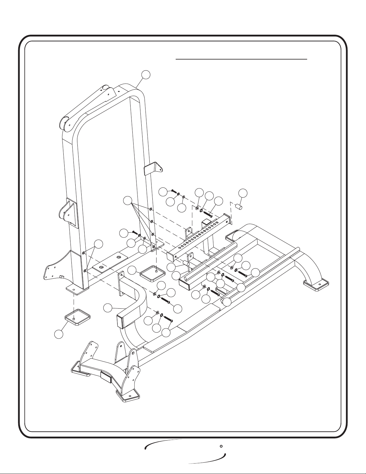
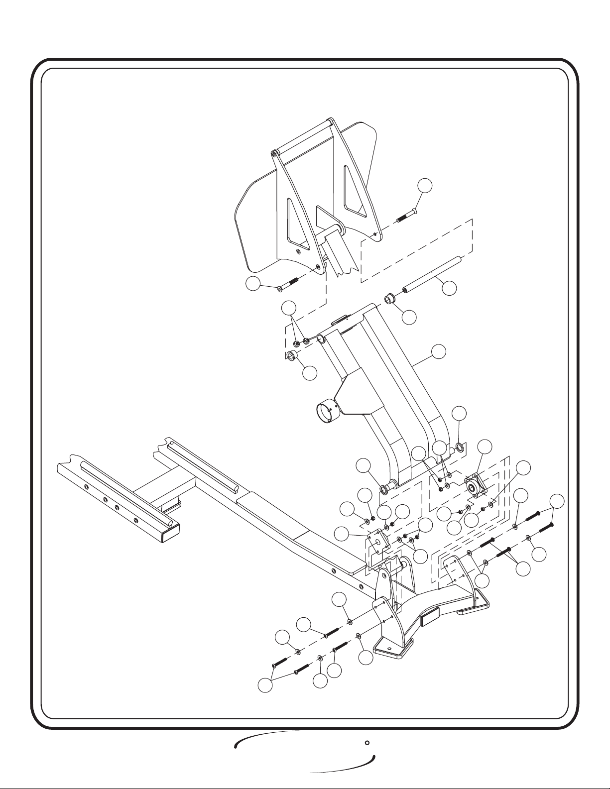
Step 2b
FRAME ASSEMBLY
In this step, start by attaching the Weight Cage to the Front Attachment
Assembly and the Seat Adjustment, Front Mount Lower Assembly. Next lift
machine to position Rubber Foot Pads. Attach the two 2” Delrin Stoppers to
the Seat Slide Adjuster. bolts only, they will be tightened later.Hand Tighten
Part Descriptions
1 - Weight Cage
3 - Front Attachment Assembly
7 - Seat Adjustment, Front Mount Lower
10 - Rubber Foot Pads
55 - Delrin Stopper
(2” LG)
Hardware Descriptions
A - 1/2”-13 x 1 1/2” Button Head Screw
B - 1/2”-13 x 3” Button Head Screw
AA - 1/2” Flat Washer
AB - 1/2” Lock Washer
CB - 1/2” Insert
(White Zinc)
(White Zinc)
(White Zinc)
(White Zinc)
Page 7
HOIST
FITNESS SYSTEMS
R
2403 Assembly
ASSEMBLY
INSTRUCTIONS
FACTORY INSTALLATION INSTRUCTION ONLY
FACTORY INSTALL 6 THREADED INSERTS
1
(CB) TO THE WEIGHT CAGE (1).
10
CB
B
CB
B
AB
AA
10
3
AA
AB
AB
55
7
AA
AB
A
A
AA
AA
AA
AB
AB
AA
A
AB
55
AA
AB
A
A
A
HOIST
FITNESS SYSTEMS
R
Page - 82403 Assembly

ASSEMBLY
INSTRUCTIONS
Step 2c
FRAME ASSEMBLY
In this step start by pressing four 1” O.D. x 3/4” I.D. Flanged Oilites
into the Foot Rest Leg Assembly. Next insert the 1” Dia. x 4 7/16” Shaft
into the lower part of the Foot Rest Leg Assembly. Make sure the 1/8”
hole on the Shaft is in line with the 3/16” hole on the Foot Rest Assembly.
Then insert any small metal pin to hold the shaft with 1/8” hole to align
for bolting. Then remove the small metal pin when finished. Place
Rubber Grip (cut to fit) on both ends of the 1”Dia x 4 7/16”. Next attach
the Foot Rest Leg Assembly to the Running Base Assembly as shown.
Insert the 8 29/32” Long Shaft onto the upper part of the Foot Rest Leg
Assembly. Make sure the 1/8” hole on the Shaft is in line with the 3/16”
hole. Then insert any small metal pin into the shaft for alignment.
Remove the small metal pin when finish bolting. Attach the Foot Rest
Assembly to the Foot Rest Leg Assembly as shown. For the final step,
slide the Rubber grip onto the 12 31/32” Long Shaft and slide two
Aluminum Rings onto both side of the shaft. Attach the 12 31/32” Long
Shaft to the Foot Rest Assembly. Then bolts including all
previously hand tightened bolts
Part Descriptions
21 - Shaft
22 - Rubber Grip
23 - Aluminum Ring
24 - Foot Rest Assembly
25 - Foot Rest Leg Assembly
26 - Shaft
27 - Rubber Grip (36” LG.)
56 - Shaft
(12 31/32” LG.)
(12 9/32 LG.)
(8 29/32” LG.)
(4 7/16” LG.)
.
Hardware Descriptions
G - 1/2”-13 x 1” Flat Head Cap Screw
CB - Insert
CC - Bumper Stopper
CF - 1” I.D. Flanged Oilite
Wrench tighten
(White Zinc)
Page 9
HOIST
FITNESS SYSTEMS
R
2403 Assembly
ASSEMBLY
INSTRUCTIONS
22
21
23
24
23
G
G
G
G
CF
CF
25
26
CB
HOIST
2403 Assembly Page - 10
FITNESS SYSTEMS
CC
(CUT TO FIT)
(CUT TO FIT)
56
CB
.550”
.550”
R
27
CF
CF
G
G
.550”
.550”
(CUT TO FIT)
(CUT TO FIT)
27

ASSEMBLY
INSTRUCTIONS
Step 2d
FRAME ASSEMBLY
In this step start by pressing two 1 3/8” O.D. x 1” I.D. Flanged
Oilites on both sides of the Foot Rest Mount Assembly. Next s
lide the
Rubber Grip (cut to fit), and both Flange Bearings on both sides of the
Foot Rest Mount Assembly. Now slide the 12 31/32” Long Shaft onto the
Foot Rest Mount Assembly. Make sure the 1/8” hole on the shaft is in line
with the 3/16” hole. Place a small metal pin between the holes to secure
for assembly
. Then remove metal pin when finished.
Wrench tighten
bolts.
Part Descriptions
21 - Shaft
27 - Rubber Grip (36” LG.)
28 - Foot Rest Mount Assembly
(12 31/32” LG.)
Hardware Descriptions
G - 1/2”-13 x 1” Flat Head Cap Screw
J - 3/8”-16 x 1 1/2” Button Head Screw
AH - 3/8” Flat Washer
AK - 3/8” Lock Washer
(White Zinc)
(Black Zinc)
(White Zinc)
(White Zinc)
Page 11
BB - 3/8” Lock Nut
CF - 1 3/8” O.D. X 1” I.D. Flange Oilite
CH - Flange Bearing
HOIST
FITNESS SYSTEMS
(Black Zinc)
R
2403 Assembly
ASSEMBLY
INSTRUCTIONS
G
G
CC
CF
(CUT TO FIT)
(CUT TO FIT)
.800”
.800”
CH
27
BB
AK
AK
CF
BB
BB
AK
BB
28
AK
21
BB
(CUT TO FIT)
(CUT TO FIT)
27
BB
AK
CH
AH
.400”
.400”
AK
AH
J
AH
J
AH
J
AH
AH
J
J
HOIST
2403 Assembly Page - 12
FITNESS SYSTEMS
AH
R

ASSEMBLY
INSTRUCTIONS
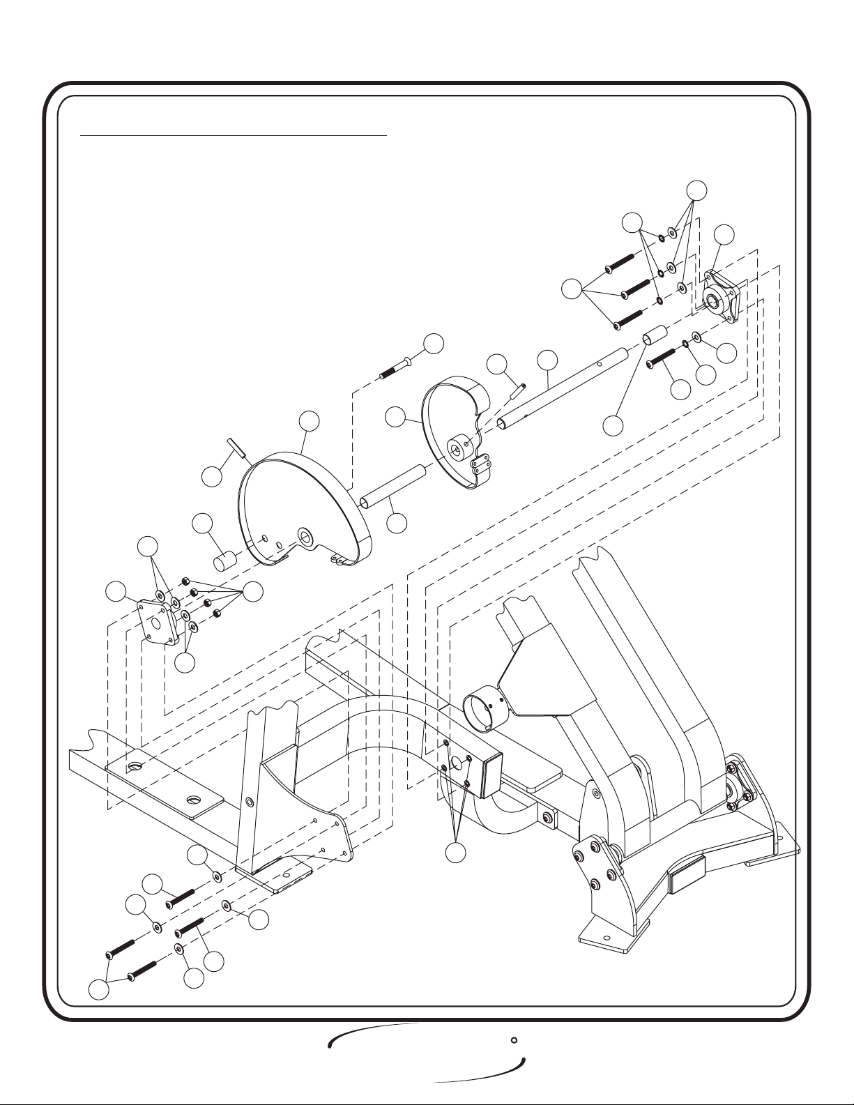
Step 2e
FRAME ASSEMBLY
Start by sliding the 14 25/32” Long Shaft onto the Small Cam Assembly
and secure it on the second hole with the 3/8” x 2” Spiral Roll Pin. Then,
slide on 1.175” O.D. x .9375 I.D. x 36” Rubber Grip (cut to fit) until it is
flush with the Small Cam Assembly. Next slide the Large Cam Assembly on
the same size shaft (14 25/32”) and secure it with another 3/8” x 2” Spiral
Roll Pin. Attach the Cam Stopper to the Large Cam Assembly on the back
hole. Next slide on 1.175 ” O.D. x .9375 I.D. x 36” Rubber Grip (cut to fit)
as shown. Now slide both Flange Bearings on each side of the 14 25/32”
Long Shaft. Then attach to the Weight Cage as shown. Make sure to put
zerk fitting facing down on Flange Bearings boltsWrench tighten .
Part Descriptions
27 - Rubber Grip
29 - Large Cam Assembly
30 - Small Cam Assembly
31 - Shaft
57 - Cam Stopper
(14 25/32” LG.)
(36” LG.)
Hardware Descriptions
J - 3/8”-16 x 1 1/2” Button Head Screw
G - 1/2”-13 x 1” Flat Head Cap Screw
V - 3/8”-16 x 1 1/4” Button Head Screw
AH - 3/8” Flat Washer
AK - 3/8” Flat Washer
BB - 3/8” Lock Nut
CH - Flange Bearing
CJ - 3/8” x 2 “ Spiral Roll Pin
CQ - Insert
( White Zinc)
(Black Zinc)
(Black Zinc)
(White Zinc)
(White Zinc)
(Black Zinc)
Page 13
HOIST
FITNESS SYSTEMS
R
2403 Assembly
ASSEMBLY
INSTRUCTIONS
FACTORY INSTALLATION INSTRUCTION ONLY
#1)
CHECK TO SEE IF FLANGE IS SQUARE. ADJUST
IF NECESSARY.
#2)
MEASURE FLANGE & FRONT ATTACHMENT
ASSEMBLY TO SEE IF BOTH ARE PARALLEL.
#3)
INSTALL CAM ASSEMBLY & ALIGN CAM TO
FRAME PULLEYS.
#4)
ALIGN PIVOT ASSEMBLY TO CAM ASSEMBLY.
AK
AJ
CH
V
CH
AK
AK
57
CJ
BB
29
30
(CUT TO FIT)
27
G
CJ
31
(CUT TO FIT)
V
27
AK
AJ
AH
J
AH
AH
J
J
2403 Assembly Page - 14
AH
HOIST
FITNESS SYSTEMS
CQ
R

ASSEMBLY
INSTRUCTIONS
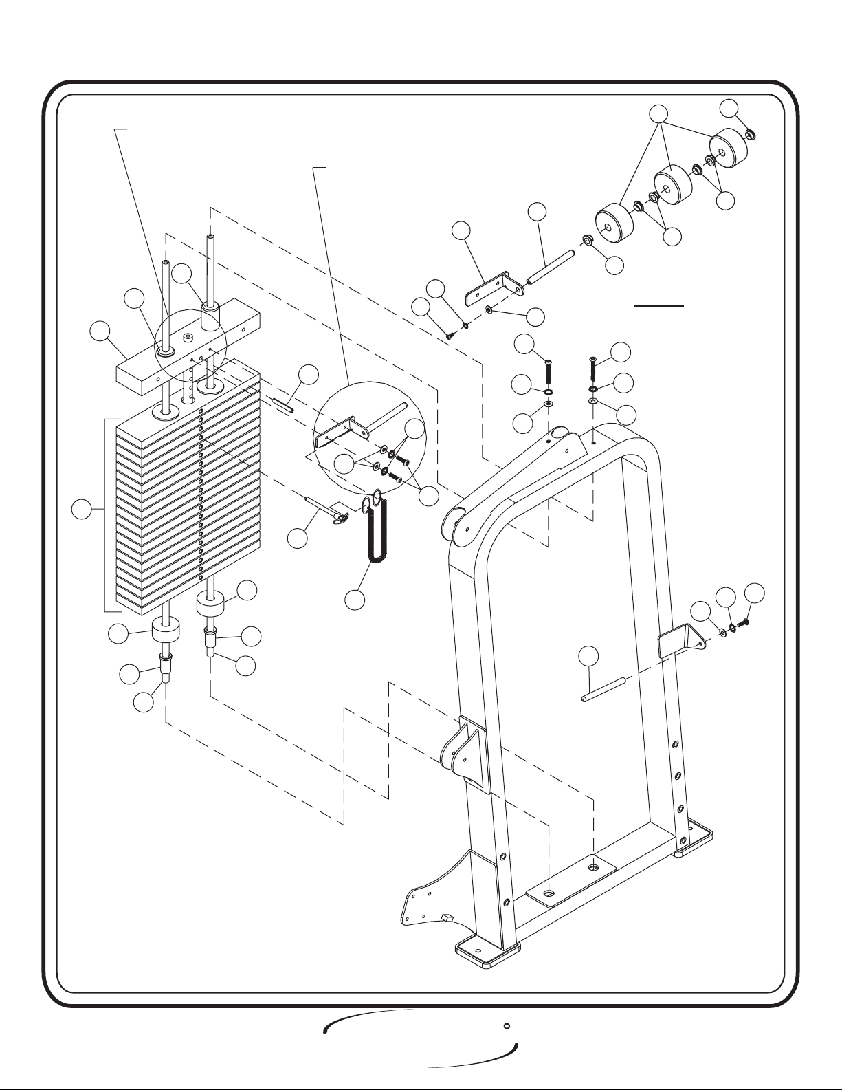
Step 2f
FRAME ASSEMBLY
In this step start by pressing the two Guide Rod Bushings into the
Weight Cage. Take the two Weight Bumpers and place them over the two
holes in the bottom of the Weight Cage. Now slide the Guide Rods into
the holes. Make sure the Guide Rods are lube with Spindle Oil. Now,
slide (20) 20 LBS. Intermediate Weight Plates and the (1) 41 LBS. Steel
Top Plate onto the Guide Rods. Make sure the Weight Stack and its
Guide Rods are sitting level. Next attach the Add On Rod to the Center
RH (BRK) Assembly. Secure the Center RH (BRK) Assembly to the 41
LBS. SteelTop Plate, slide on the three Add On Weights and attach
another Add On Rod to the Weight Cage. Attach bigger end of the
Selector Pin Lanyard to the Center RH (BRK) Assembly, and the other
end to the Weight Selector Pin. Then bolts.Wrench tighten
Part Descriptions
33 - Center RH (BRK) Assembly
34 - Add On Rods
35 - Add On Weights
36 - Weight Selector Pin
37 - Guide Rods
38 - Weight Bumpers
39 - Guide Rod Bushings
40 - 41 lbs. Steel Top Weight
41 - 20 lbs. Intermediate Weight
64 - Add On Weight Bushing
Hardware Descriptions
K - 3/8”-16 x 1” Button Head Screw
L - 5/16”-18 x 1” Button Head Screw
M - 3/8”-16 x 1” Button Head Screw
N - 3/8”-16 x 2 3/4” Flat Head Cap Screw
AG - 3/8” Lock Washer
AH - 3/8” Flat Washer
AJ - 3/8” Lock Washer
AK - 3/8” Flat Washer
AL - 5/16” Lock Washer
AM - 5/16 Flat Washer
AN - 3/8” Split Washer
CK - Selector Pin Lanyard
CM - Top Weight Roll Pin
(White Zinc)
(White Zinc)
(Black Zinc)
(Black Zinc)
(Black Zinc)
(Black Zinc)
(White Zinc)
(Black Zinc)
(Black Zinc)
(White Zinc)
(White Zinc)
Page 15
CN - Guide Bearing
CP - Guide Bearing
HOIST
FITNESS SYSTEMS
(Tall)
(Short)
R
2403 Assembly
ASSEMBLY
INSTRUCTIONS
41
FOR ASSEMBLY INSTRUCTION
SEE PAGE 30
CN
CP
40
FOR ASSEMBLY SEE A-1
CM
AM
AL
35
34
33
64
AJ
K
L
AN
AH
AK
N
N
AN
AH
64
A-1
64
64
38
39
37
38
37
39
36
CK
34
AH
AG
M
R
HOIST
2403 Assembly Page - 16
FITNESS SYSTEMS

ASSEMBLY
INSTRUCTIONS
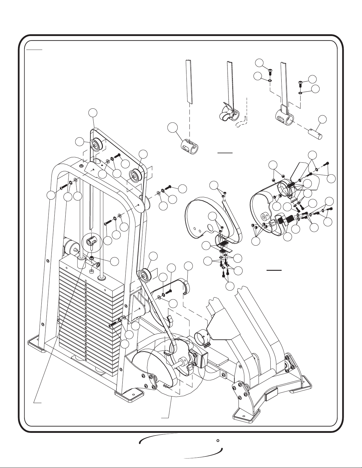
Step 2g
FRAME ASSEMBLY
In this step start by attaching the Belt Assembly to the Weight
Assembly (prior to attaching the Cam Belt). Place smooth side of Cam
Belt on the Pulley and Cam. Next slide the Cam Belt through the Pulley
Bracket on the top of the Weight Cage. Then use a Seat Clamp On tool to
secure the two 3 1/4” Pulleys to the Weight Cage under the Cam Belt.
Slide the Cam Belt into the top slot of the 1 5/8”x 2 1/16” LG. Tube (Fig.
1). Loop the end of the Cam Belt and feed it back up through the slot,
keeping the loop open (Fig. 2). Next slide the Belt Retainer Shaft through
the Cam Belt and line up the holes, then secure to the 1 5/8” x 2 1/16”
LG. Tube (Fig. 3). Next attach the Cam Belt by bringing it down and
through the pulley bracket behind the 3 1/4” Pulley. Now bring the Cam
Belt around the Large Cam Assembly and in between the Serrated
Clamps. Then wrap the Cam Belt down and around the Serrated Clamp
and above another Serrated Clamp and secure all of the Serrated Clamps
together. Next wrap the short cam belt on the Small Cam Assembly as
shown. bolts.Wrench tighten
Part Descriptions
42 - Cam Belt
44 - Cam Belt
45 - Serrated Clamps
46 - Belt Retainer Shaft
47 - Tube
(110” LG.)
(42” LG.)
(1 5/8” x 2 1/16” LG.)
Hardware Descriptions
P - 3/8”-16 x 3/4” Button Head Screw
Q - 1/4”-20 x 1 1/4” Socket Head Screw
R - 1/4”-20 x 3/4” Button Head Screw
AG - 3/8” Lock Washer
AH - 3/8 Flat Washer
AP - 1/4” Lock Washer
BC - 3/8” Lock Nut
BD - 1/4” Lock Nut
(White Zinc)
(White Zinc)
(Black Zinc)
(Black Zinc)
(White Zinc)
(White Zinc)
(Black Zinc)
(Black Zinc)
Page 17
CL - 3 1/4” Pulley
HOIST
FITNESS SYSTEMS
R
2403 Assembly
ASSEMBLY
INSTRUCTIONS
NOTE: 1. BELT SMOOTH SIDE DOWN, ALWAYS
FOR TWO TOP PULLEYS AND CAM.
SMOOTH SIDE TO WRAP AROUND
BELT RETAINER SHAFT
2. WHEN TIGHTENING THE CLAMPS
(45) TO THE BELT DO NOT EXCEED
70 IN. LBS.
42
CL
CL
P
AG
AH
P
AG
AH
AH
AG
P
AH
FIGURE 1FIGURE 1 FIGURE 3FIGURE 3FIGURE 2FIGURE 2
46
P
AG
BD
BD
45
B-1
BD
AP
R
R
AP
47
AP
BD
Q
AP
Q
Q
BD
Q
45
45
AP
Q
AP
FOR ASSEMBLY SEE B-1
FOR ASSEMBLY SEE B-2
BC
P
AG
AH
CL
AG
P
AH
44
Q
AP
AP
Q
B-2
R
HOIST
2403 Assembly Page - 18
FITNESS SYSTEMS

ASSEMBLY
INSTRUCTIONS
Step 2h
FRAME ASSEMBLY
In this step, attach the Linear Pillow Block Bearings to the Seated
Assembly. Before Sliding the Seated Assembly onto the Long Stand-Off Rail
and the Short Stand-Off Rail, make sure the rails are apply with grease. Now
attach (65) to (4). bolts including all previously hand tightened
Wrench tighten
bolts.
Part Descriptions
9 - 2” x 4” End Cap
11 - Seated Assembly
14 - Pull Pin
65 - 1/4” Stainless Steel Plate
(HH)
Hardware Descriptions
D - 10-24 x 3/4” Button Head Screw
X - 3/8”-16 x 1” Flat Head Screw
AE - 10mm Flat Washer
CC - Bumper Stopper
CD - Linear Pillow Block Bearing
CQ - 3/8” Inserts
(White Zinc)
(White Zinc)
R
HOIST
Page - 19 2403 Assembly
FITNESS SYSTEMS
ASSEMBLY
INSTRUCTIONS
9
CQ
14
X
65
X
4
CQ
CD
AE
AE
CD
AE
D
CC
11
CD
AE
AE
D
AE
D
HOIST
FITNESS SYSTEMS
R
Page - 202403 Assembly
 Loading...