

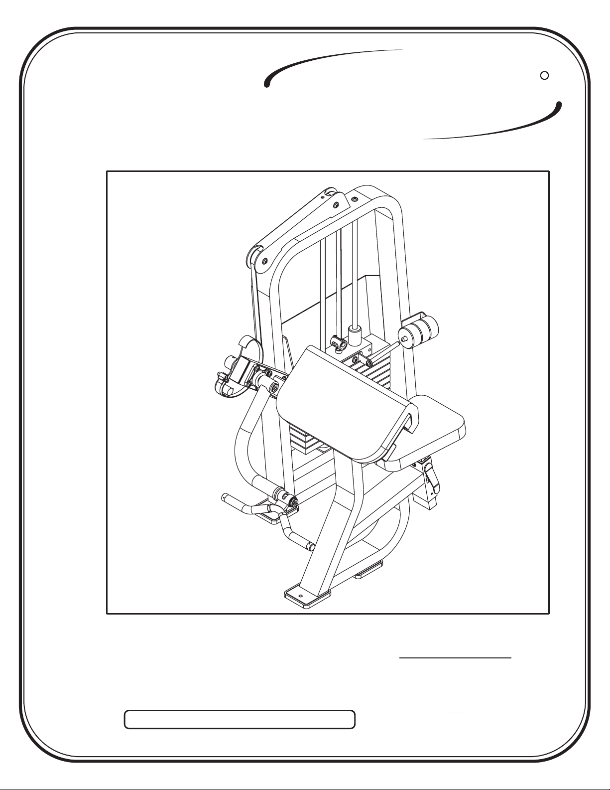
Hoist Fitness CL-2103 User Manual
HOIST
FITNESS SYSTEMS
CL-2103
R
Note: Both Serial Number and Model Number are Required when Ordering Parts
RECORD SERIAL NUMBER HERE
OWNERS MANUAL
August 2000
Customer Service
(800) 548-5438
(619) 578-7676
Fa x
(619) 578-9558

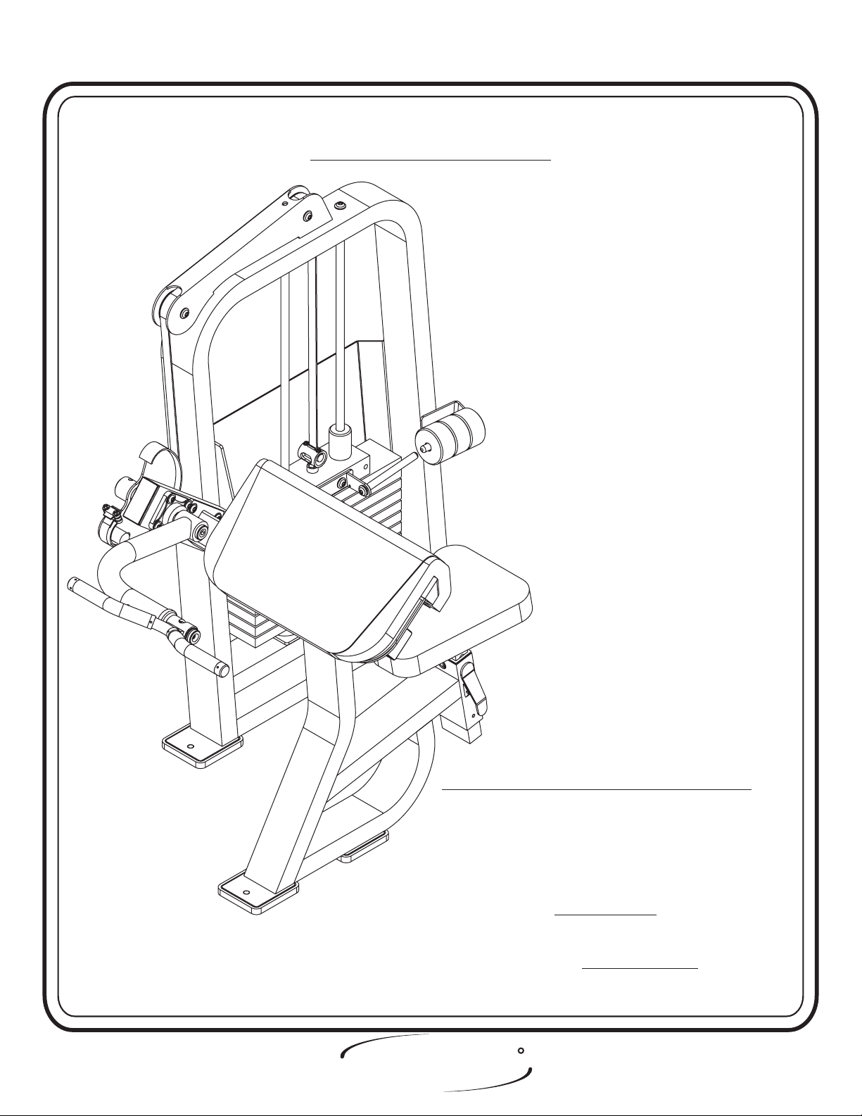
ASSEMBLY
INSTRUCTIONS
CONTENTS
INSTRUCTIONS (Step 1) .............................................................
FRAME ASSEMBLY (Step 2) ........................................................
PARTS LISTING ............................................................................
HARDWARE LISTING ..................................................................
BOLT SIZING CHART ..................................................................
WASHER SIZING CHART ............................................................
WEIGHT RATIOS .........................................................................
WEIGHT TRAINING TIPS ...........................................................
WEIGHT TRAINING EXERCISE LOG ......................................
2
4
23
24
26
27
28
30
32
DECAL PLACEMENTS ....................................................................
GENERAL MAINTENANCE..........................................................
LIMITED WARRANTY ..................................................................
R
HOIST
Page - 1 2103 Assembly
FITNESS SYSTEMS
34
39
42

ASSEMBLY
INSTRUCTIONS
Step 1
INSTRUCTIONS
Before beginning assembly please take the time to read the
instructions thoroughly. Please use the catalog in this manual to
make sure that all parts have been included in your shipment.
When ordering use the part number and description from the
catalog.
Use only Hoist replacement parts when servicing. Failure
to do so will void your warranty and could result in personal
injury.
Hoist equipment is designed to provide the smoothest, most
effective exercise motion possible. After assembly, you should
check all functions to ensure correct operation. If you
experience problems, first recheck the assembly instructions to
locate any possible errors made during assembly. If you are
unable to correct the problem, call your authorized Hoist dealer.
Be sure to have your serial number and this catalog when calling.
When all parts have been accounted for, continue on to Step 2.
TOOLS REQUIRED
Standard Allen Wrench Set
(2.5mm, 3/32” - 5/16”)
Crescent Wrench
Belt Tensioning Wrench
(Hoist Tool SM374)
Rubber Mallet
Tape Measure
R
HOIST
FITNESS SYSTEMS
Page - 22103 Assembly

ASSEMBLY
INSTRUCTIONS
R
HOIST
Page - 3 2103 Assembly
FITNESS SYSTEMS
ASSEMBLY
INSTRUCTIONS
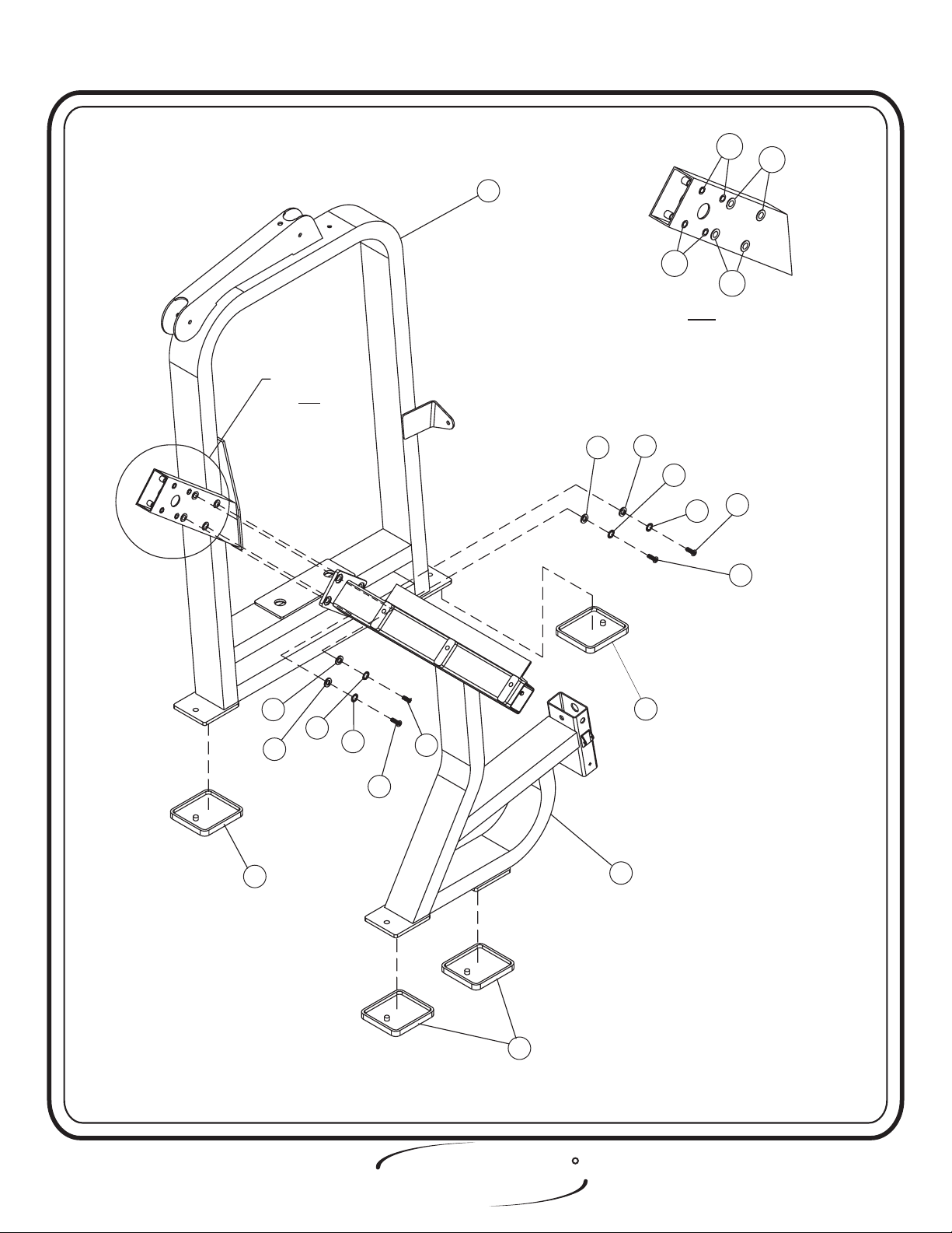
Step 2
FRAME ASSEMBLY
FACTORY INSTALLATION INSTRUCTION ONLY
1. ALL THREADED HOLES SHOULD BE TAPPED,
EXCEPT INSERTS.
2. ALL CALLED OUT INSERTS MUST BE INSTALLED BEFORE
ANY ASSEMBLY.
3. PUT A DROP OF ON BOLTS IF
NECESSARY.
4. IF NECESSARY APPLY TO ALL
BEARINGS.
HOIST
FITNESS SYSTEMS
BLUE LOCTITE 242
GREEN LOCTITE 680
R
Page - 42103 Assembly

ASSEMBLY
INSTRUCTIONS
Step 2a
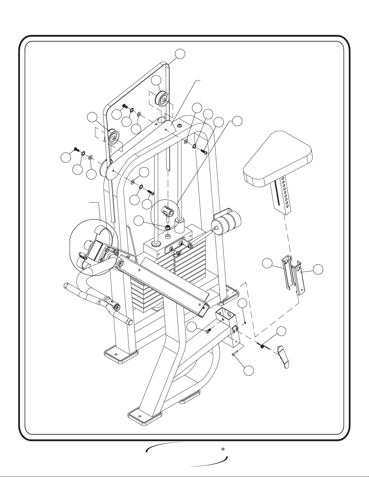
FRAME ASSEMBLY
In this step attach the Weight Cage to the Seated Frame.
Hand Tighten
bolts only, they will be tightened later. Lift Machine to position Rubber
Feet.
Part Descriptions
1 - Weight Cage
2 - Seated Frame
Hardware Descriptions
A - 1/2-13 x 1 1/2” Button Head Screw
B - 1/2” Flat Washer
T - 1/2” Lock Washer
AM - 3/8”-16 Insert
AL - 1/2”-13 Insert
AQ - 4.74” x 5.24” x .625 Rubber Foot Pad
R
HOIST
Page - 5 2103 Assembly
FITNESS SYSTEMS
For clarity
For clarity
see A-1
see A-1
ASSEMBLY
INSTRUCTIONS
1
All inserts are factory installed, non-removable
All inserts are factory installed, non-removable
AM have 4 on both sides of mount)
(Inserts AM have 4 on both sides of mount)
(Inserts
AM
A-1
A-1
AM
AL
AL
AQ
B
B
T
B
T
A
A
B
T
A
T
A
AQ
2
AQ
HOIST
FITNESS SYSTEMS
R
Page - 62103 Assembly

ASSEMBLY
INSTRUCTIONS
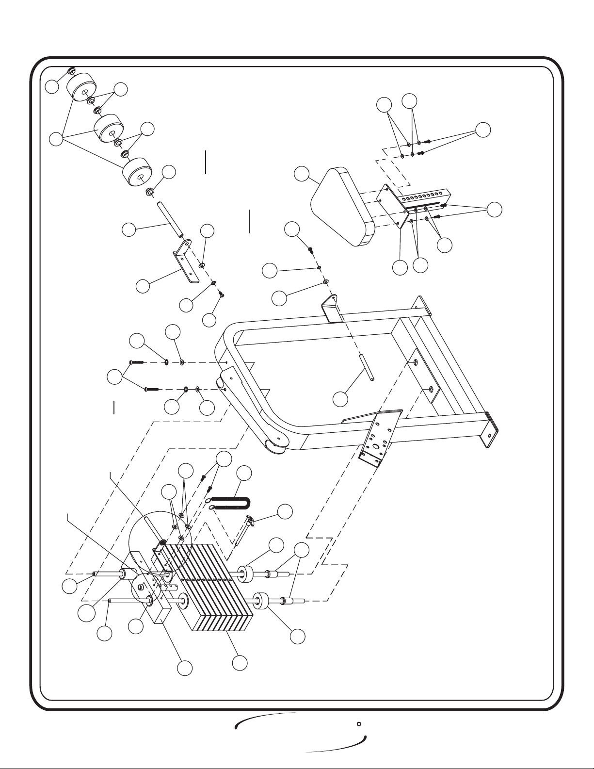
Step 2b
FRAME ASSEMBLY
In this step, start by sliding one 1 ¼” dia. x 3/8” Aluminum Ring on each side of
the Handle Assembly. Then, slide on one 1.25” O.D. x 1.030” I.D. x 8.25” Comfort grip
on each side. Placea1¼Dia. x 3/4” Aluminum Cap on the end of the Handle Assembly.
Once all three pieces(per side) are in place, secure the End Caps, slide the Comfort
Grip flush with the End Caps, and slide the Aluminum Rings flush with the Comfort
Grip and secure. Next, secure a 1 3/8” Dia. Flat Head Cap to the elbow of the Arm
Assembly. Then attach the two Flange Bearings to the Weight Cage. Make sure to put
zerk fitting facing down on Flange Bearings. Then, press both 1” Oilite Bushings on
the ends of the Handle Assembly. Now attach the Pivot Assembly to the Arm Assembly.
Slide one Metal Shim Washer on to the shaft of the Pivot Assembly. Attach the
Handle
Assembly to the Pivot Assembly and slide on another Shim Washer, place a 1 3/8”
diameter Flat Head Cap and secure, then check for side to side play. If there is play,
remove the Handle Assembly and add another Shim Washer to each side of the Handle
Assembly. Repeat if necessary until there is no noticeable
play and the Hand Bar still
moves freely. Slide the entire Arm Assembly through the Flange Bearings and the
Weight Cage, insert the end into the Cam Assembly and secure with the 3/8” x 2” Open
Roll Pin. bolts only, they will be tightened later.Hand Tighten
Part Descriptions
3 - Arm Assembly
4 - Pivot Assembly
5 - Handle Assembly
6 - Cam Assembly
28 - Black Plastic Ring
Hardware Descriptions
C - 3/8” x 1” Flat Head Cap Screw
D - 3/8” x 1 1/4” Button Head Screw
E - 3/8” Flat Washer
H - 3/8” x 3/4” Socket Head Cap Screw
M - 3/8” x 3/4” Button Head Screw
P - 3/8” Lock Washer
V - 3/8” x 2” Open Roll Pin
W - 3/8” Lock Washer
X - 1” I. D. x .8mm Thick Metal Shim Washer
Y
- #10-32 Set Screw
AA - 1 3/8” Dia. Flat Head Cap, 3/8”I. D. x 5/16” Thick
AB - 1” I.D. Oilite Bushing
AC - Flange Bearing
AN - 1.25” O.D. x 1.03 I.D. x 8.25 Comfort Grip
AU - 1 1/4” dia. x 3/4” Aluminum Cap
AV-11/4”d
BD - 1 5/8” Dia. Aluminum Flat Head Cap, Red
ia. x 3/8” Aluminum Ring
R
HOIST
Page - 7 2103 Assembly
FITNESS SYSTEMS

longest
the
5
Make Sure the longest
Make Sure
down.
facing
is
side
slot
slot side is facing down.
AV
AN
ASSEMBLY
INSTRUCTIONS
Y
AU
AU
AN
Y
AV
Y
tolerance
to
depend
will
due
A-1
Y
D
W
E
V
28
gap
Quantity will depend
Quantity
on gap due to tolerance
on
BD
M
C
P
AB
X
W
X
AB
5
4
H
3
P
M
D
C
AA
detail A-1
see
clarity
For clarity see detail A-1For
17-18
page
see
Assembly
For Assembly
For
instructions see page 17-18
instructions
E
E
D
6
W
W
D
HOIST
FITNESS SYSTEMS
AC
E
R
Page - 82103 Assembly

ASSEMBLY
INSTRUCTIONS
Step 2c
FRAME ASSEMBLY
In this step start by pressing two Guide Rod Bushings into the Weight Cage.
Take the two 3” x 1” I.D. Bumpers and place them over the two holes in the bottom
of the Weight Cage and slide the Guide Rods into the holes. Make sure the Guide
Rods are lube with Spindle Oil. Now slide the 20 LBS. Intermediate Weight Plates
and 15 LBS. Aluminum Top Plate onto the Guide Rods and secure. Make sure the
Weight Stack and its Guide Rods are sitting level. Next, attach the 5/8” Dia. x 6
13/32” Rod to the Center RH BRK (Add-On). Secure the Center RH BRK (Add-On)
to the 15 LBS. Aluminum Top Plate. Slide on three 5 LBS. Add-On Weights and
attach the 5/8” Dia. x 6 13/32” Rod to the Weight Assembly. Attach the 12” x 14 1/2”
Upholstery Seat to the Seat Adjuster. Attach one end of the Selector Pin Lanyard to
the 15 LBS. Aluminum Top Plate, and the other end to the Weight Selector Pin.
Then bolts including all previously hand tightened boltsWrench tighten .
Part Descriptions
7 - 41 13/16 x 3/4” Dia. Guide Rod
8 - 20 LBS. Intermediate Weight
9 - 15 LBS. Aluminum Top Plate
10 - 3” x 1” I.D. x 1 1/2” THK Bumper
11 - Guide Rod Bushing (PLAS 134)
12 - Center RH BRK (Add-on)
13 - 12” x 14 1/2” Upholstery Seat
14 - Seat Adjuster
22 - 5/8” Dia. x 6 13/32” Rod
27 - Add On Weight Bushing
Hardware Descriptions
J - 5/16” x 1 1/4” Button Head Cap Screw
K - 3/8” x 2 3/4” Button Head Cap Screw
L - 5/16” Flat Washer
P - 3/8” Lock Washer
S - 3/8” x 1” Button Head Cap Screw
U - 5/16” Lock Washer
Z - 3/8” Split Washer
AR - 5 LBS. Add on Weight
AS - Weight Selector Pin
AT - Selector Pin Lanyard
AX - Guide Bearing
AY - Guide Bearing
BC - 5/16” x 1” Button Head Screw
BF - 5/16” Lock Washer (black)
BG - 3/8” Flat Washer (white zinc)
BH - 3/8” Lock Washer (black)
BJ - 5/16” Flat Washer (white zinc)
R
HOIST
Page - 9 2103 Assembly
FITNESS SYSTEMS
ASSEMBLY
INSTRUCTIONS
27
AR
27
22
U
BJ
27
BG
BH
A-1
13
E
BE
A-1
S
U
P
BG
14
BJ
27
12
Z
J
J
21-22
page
see
assembly
For assembly
For
instructions see page 21-22
instructions
7
AY
K
see A-1
clarity
For clarity see A-1For
7
AX
Z
L
BF
BG
BC
AT
10
AS
11
10
22
9
8
HOIST
FITNESS SYSTEMS
R
Page - 102103 Assembly

ASSEMBLY
INSTRUCTIONS
Step 2d
FRAME ASSEMBLY
In this step start by
Assembly(prior to attaching the Cam Belt). Next,
attaching the Belt Assembly to the Weight
slide the Cam Belt
through the Roller Bracket on the top of the Weight Cage. Then, secure
the two 3 1/4” Pulleys to the Weight Cage under the Cam Belt. Next,
attach the Latch Assembly to the Seated Assembly by sliding the 1.55 x
.25 Dia. Shaft through the mounts and through the Adjustment Spring
and secure with the C-Clip; also, insure that the Adjustment Spring ends
are pointing down to ensure that the Latch Assembly locks the Seat
Adjuster in place. Next slide the two EZ Glide Sleeves into the Seated
Assembly from the top down until the locating boss snaps into the
location hole. Next slide the Seat Adjuster in the Seated Assembly.
tighten
bolts.
Wrench
Part Descriptions
14 - Seat Adjuster
15 - Belt Assembly
17 - Latch Assembly
20 - Cam Belt
Hardware Descriptions
M - 3/8” x 3/4” Button Head Cap Screw
P - 3/8” Internal Lock Washer
R - C-Clip
AD - 3 1/4” Pulley
AE - EZ Glide Sleeve
AF - Adjustment Spring
AG - 1.55 x .25 Dia. Shaft
AP - 3/8” x 3/4” Square Head Set Screw
BB - 1/4” Locking Nut
BG - 3/8” Flat Washer (white zinc)
BL - Serrated Hex Nut
R
HOIST
Page - 11 2103 Assembly
FITNESS SYSTEMS
ASSEMBLY
INSTRUCTIONS
20
M
P
For Assembly
For Assembly
instructions see page 17-18
instructions
see page 17-18
AD
BG
M
AD
Roller BracketRoller Bracket
BG
P
P
M
For assembly
For assembly
15
instructions see page 19-20
instructions
see page 19-20
BG
BG
P
M
BB
AP
AE
AE
R
AF
AG
HOIST
FITNESS SYSTEMS
R
Page - 122103 Assembly
 Loading...