

Hoist Fitness CL2061 User Manual
HOIST
FITNESS SYSTEMS
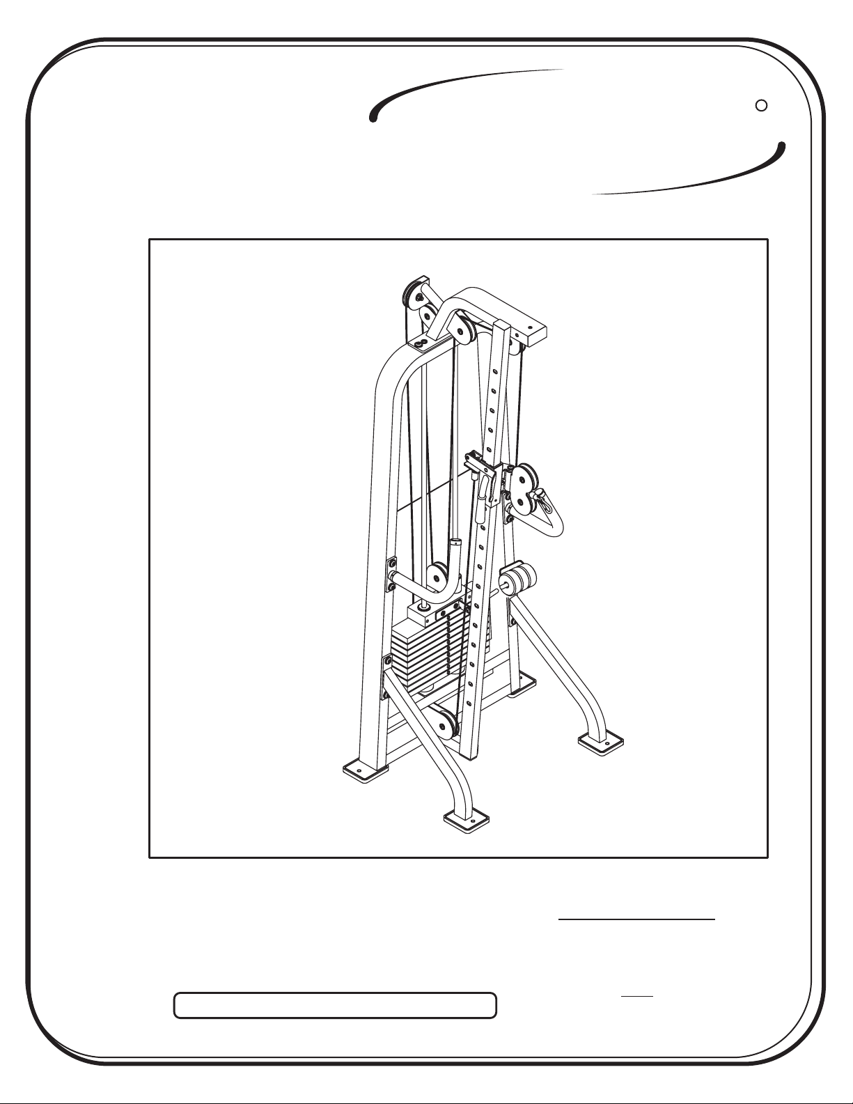
CL2061
R
Note: Both Serial Number and Model Number are Required when Ordering Parts
RECORD SERIAL NUMBER HERE
OWNERS MANUAL
March 2000
Customer Service
(800) 548-5438
(619) 578-7676
Fa x
(619) 578-9558
ASSEMBLY
INSTRUCTIONS
CONTENTS
INSTRUCTIONS (Step 1)
FRAME ASSEMBLY (Step 2)
PRE-ASSEMBLED PARTS (Step 3)
PARTS LISTING
HARDWARE LISTING
BOLT SIZING CHART
WASHER SIZING CHART
WEIGHT RATIOS
WEIGHT TRAINING TIPS
2
4
21
23
24
25
26
27
29
Page - 1
WEIGHT TRAINING EXERCISE LOG
DECAL REFERENCE
GENERAL MAINTENANCE
LIMITED WARRANTY
HOIST
FITNESS SYSTEMS
31
33
35
37
R
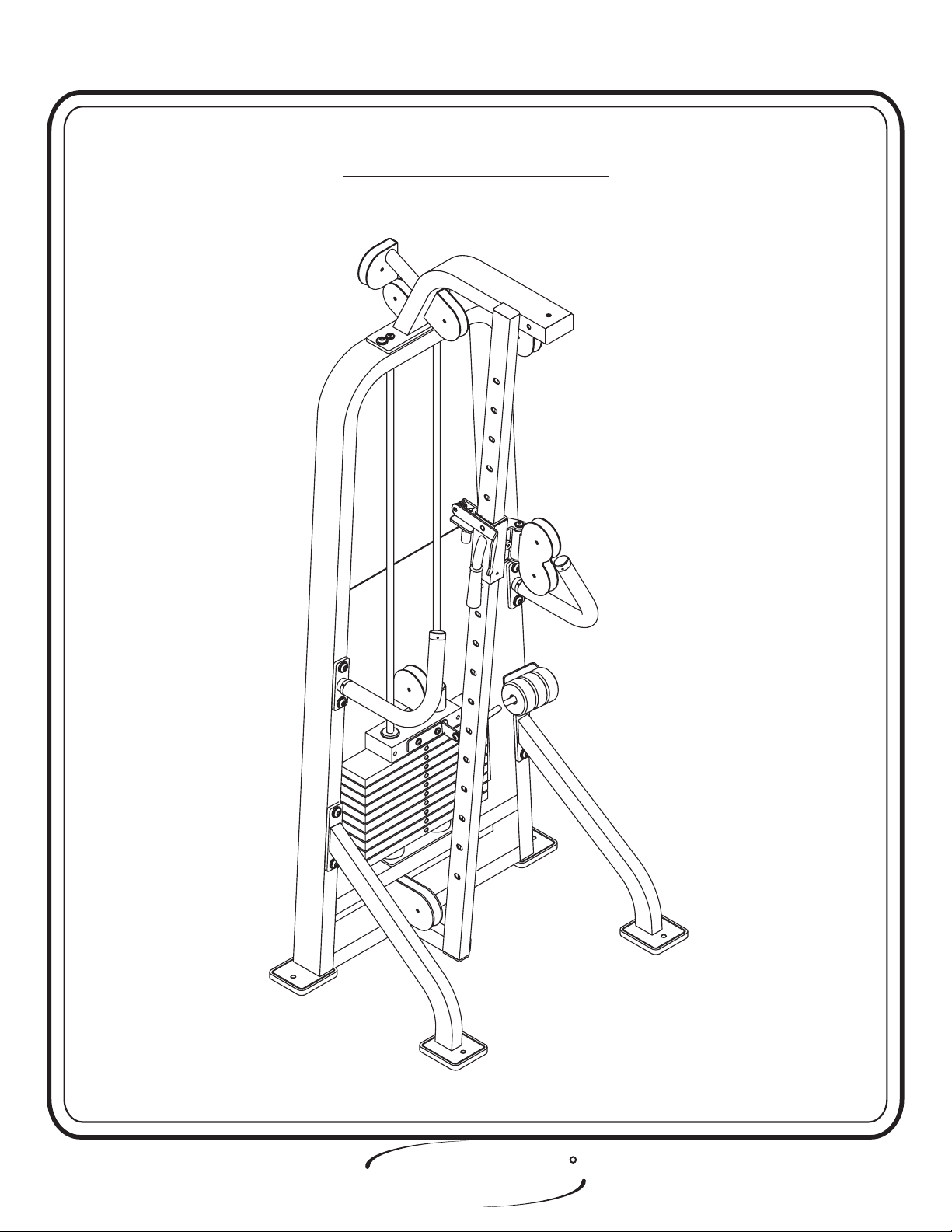
2061 Assembly
ASSEMBLY
INSTRUCTIONS
Step 1
INSTRUCTIONS
Before beginning assembly please take the time to read the
instructions thoroughly. Please use the catalog in this manual to
make sure that all parts have been included in your shipment.
When ordering use the part number and description from the
catalog.
Use only Hoist replacement parts when servicing. Failure
to do so will void your warranty and could result in personal
injury.
Hoist equipment is designed to provide the smoothest, most
effective exercise motion possible. After assembly, you should
check all functions to ensure correct operation. If you
experience problems, first recheck the assembly instructions to
locate any possible errors made during assembly. If you are
unable to correct the problem, call your authorized Hoist dealer.
Be sure to have your serial number and this catalog when calling.
When all parts have been accounted for, continue on to Step 2.
TOOLS REQUIRED
Standard Allen Wrench Set
(3/32” - 5/16”)
Crescent Wrench
Rubber Mallet
Tape Measure
R
HOIST
FITNESS SYSTEMS
Page - 22061 Assembly

Page - 3
HOIST
FITNESS SYSTEMS
R
2061Assembly
ASSEMBLY
INSTRUCTIONS
Step 2
FRAME ASSEMBLY
HOIST
FITNESS SYSTEMS
R
Page - 42061Assembly
In this step attach (2), (3), and (4) to (1). Wrench tighten bolts. Lift
machine to position (5).
ASSEMBLY
INSTRUCTIONS
Step 2a
FRAME ASSEMBLY
Part Descriptions
1 - Frame Assembly
2 - Front Support Left
3 - Front Support Right
4 - Rear Support Assembly
5 - Rubber Foot Pad
Hardware Descriptions
A - 1/2”-13 x 1 1/2” Button Head Screw
AA - 1/2” Lock Washer
AB - 1/2” Flat Washer
(White Zinc)
(White Zinc)
(White Zinc)
Page 5
HOIST
FITNESS SYSTEMS
R
2061Assembly

ASSEMBLY
INSTRUCTIONS
1
AA
A
AB
5
AA
AB
4
AB
AA
A
5
AB
AA
A
AB
AA
5
A
3
5
HOIST
FITNESS SYSTEMS
2
5
R
Page - 62061Assembly
ASSEMBLY
INSTRUCTIONS
Step 2b
FRAME ASSEMBLY
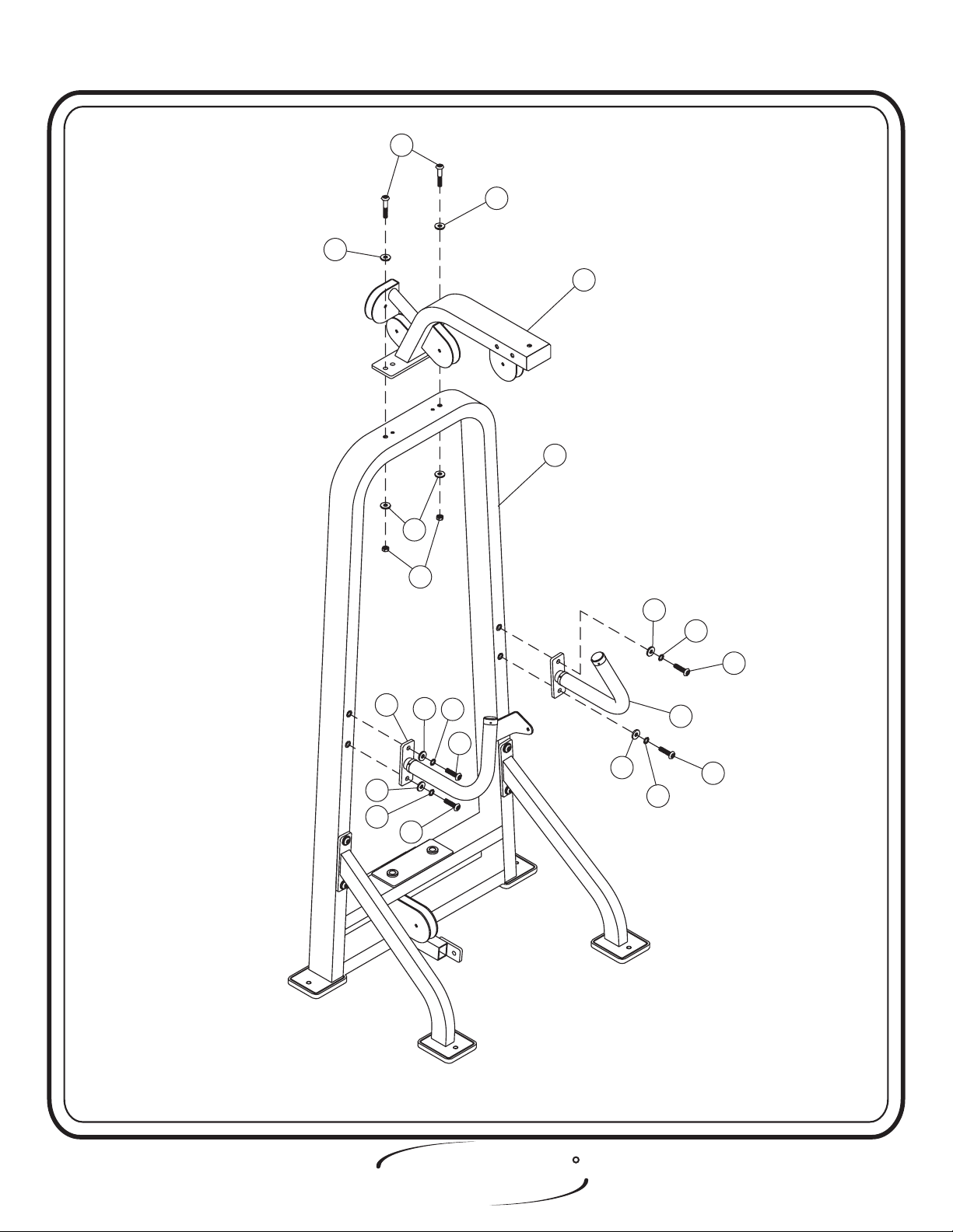
Attach (6), (7), and (8) to (1). Wrench tighten bolts.
Part Descriptions
1 - Frame Assembly
6 - Handle Assembly Right
7 - Handle Assembly Left
8 - Top Pulley Mount Assembly
Hardware Descriptions
A - 1/2”-13 x 1 1/2” Button Head Screw
B - 1/2”-13 x 3” Button Head Screw
AA - 1/2” Lock Washer
AB - 1/2” Flat Washer
BA - 1/2” Lock Nut
(White Zinc)
(White Zinc)
(White Zinc)
Page 7
HOIST
FITNESS SYSTEMS
R
2061Assembly
ASSEMBLY
INSTRUCTIONS
B
AB
AB
8
1
AB
AA
AB
BA
AB
AA
A
7
AB
AA
A
AB
A
6
A
AA
HOIST
FITNESS SYSTEMS
R
Page - 82061Assembly
ASSEMBLY
INSTRUCTIONS
Step 2c
FRAME ASSEMBLY
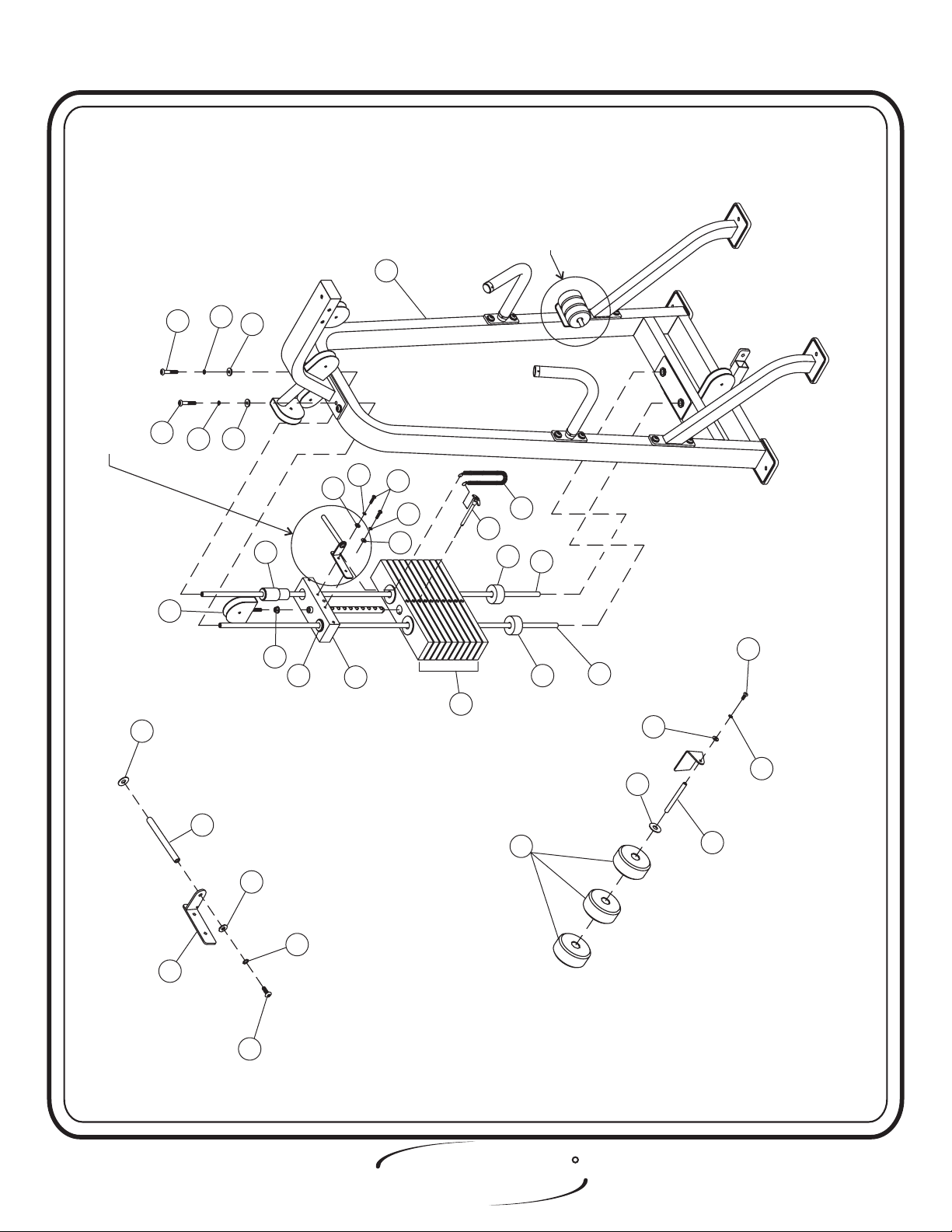
In this step, start by pressing (CB) and (CA) into (12), insuring (CB)
is pressed in the same side as (14) is mounted to (13). Place (9) over the
two holes in the bottom of (1). Now slide (9) into the holes. Slide (11)
and (12) onto (9). Make sure (12), (11), and (9) are sitting level, then
fasten the top of each (9) to (1). Next attach (14) to (13). Secure (13) to
(12), slide on (16) and attach another (14) to (1). Attach bigger end of the
(CC) to (13), and the other end to (17). Then bolts.Wrench tighten
Part Descriptions
1 - Frame Assembly
9 - Guide Rod
10 - Weight Bumper
11 - 20 LB. Intermediate Weight
12 - 8.6 LB Aluminum Weight
13 - Center RH (BRK) Assembly
14 - Add on Rod
15 - Cable Pulley Weight Mount Assembly
16-5LBCast Add on Weight
17 - Weight Selector Pin
Hardware Descriptions
C - 3/8”-16 x 3 1/2” Button Head Screw
D - 5/16”-18 x 1” Button Head Screw
E - 3/8”-16 x 1” Button Head Screw
F - 3/8”-16 x 1” Button Head Screw
AC - 3/8” Split Washer
AD - 3/8” Flat Washer
AE - 5/16” Lock Washer
AF - 5/16” Flat Washer
AG - 3/8” Flat Washer
AH - 3/8” Lock Washer
AJ - 3/8” Lock Washer
AK - 5/8” Nylon Washer
BB - Serrated Hex Nut
CA - Guide Bearing (Short)
CB - Guide Bearing (Tall)
Page 9
CC - Selector Pin Lanyard
HOIST
FITNESS SYSTEMS
R
2061Assembly
for
A
instructions
ASSEMBLY
INSTRUCTIONS
for
B
instructions
detail
See detail B for
See
assembly instructions
assembly
1
C
AC
AD
detail
See detail A for
See
assembly instructions
assembly
AK
C
15
AC
14
AD
CB
BB
CA
AF
AE
12
D
AF
AE
11
17
10
CC
16
9
10
F
9
AD
AJ
AK
14
13
AG
E
AH
Detail ADetail A
HOIST
FITNESS SYSTEMS
Detail BDetail B
R
Page - 102061Assembly
ASSEMBLY
INSTRUCTIONS
Step 2d
FRAME ASSEMBLY
FRAME ASSEMBLY
Continue assembling the CL2061 by sliding (19) into (18) and
attaching (18) to (20). Next attach (21) to (20) and slide (20) on (23).
Secure (23 to (8) and (1). .Wrench tighten bolts
Part Descriptions
18 - Sliding Pulley Mount
19 - Shaft
20 - Pulley Mount
21 - Pulley Mount Adjustment Lever
22 - Plastic Block
23 - Pulley Mount Adjuster Bar
24 - Latch Pin
Hardware Descriptions
A-1/2”-13x1½Button Head Screw
F - 3/8”-16 x 1 Button Head Screw
G-1/2”-13x5HexHead Bolt
H - 1/2”-13 x 1 Flat Head Allen Screw
AA - 1/2” Lock Washer
AB - 1/2” Flat Washer
AD - 3/8” Flat Washer
AJ - 3/8” Lock Washer
CD - C-Clip
CE - Century Spring 3894
Page - 11
HOIST
FITNESS SYSTEMS
R
2061 Assembly
 Loading...