

Hohner UNIVERSAL 43/6 S Operating Instructions Manual
Hohner Maschinenbau GmbH
Gänsäcker 19, 78532 Tuttlingen, Telefon 07462/9468-0, Telefax 07462/9468-20
1 :egaP snoitcurtsnI-gnitarepO
Spare parts list E1
UNIVERSAL
43/6 S
Narrow Stitching Head
Edition 01/2008
CPB 9134121

HK 43/6 S Hohner Maschinenbau GmbH
2

Hohner Maschinenbau GmbH HK 43/6 S
3
Customer Entries
Stitching head no: ...........................
Machine manufacturer: ...........................
Type of manufacturer: ...........................
Manufacturer' s Address
Company name: Hohner Maschinenbau GmbH
Street: Gänsäcker 19
Town: D-78532 Tuttlingen
Telephone: +49 7462 / 9468-0
Fax: +49 7462 / 9468-20
Email: info@hohner-gmbh.de
Internet: http://www.hohnerstitching.com
Spare Parts / Customer Service
Service telephone no: +49 7462 / 9468-23

List of Contents
HK 43/6 S Hohner Maschinenbau GmbH
4
List of Contents
1 SAFETY INFORMATION 6
1.1 Purpose of this document ...............................................................................................6
1.2 The operator....................................................................................................................6
1.3 Safety symbols and the displays that have been used...................................................6
1.4 Obligation and liability .....................................................................................................7
1.5 Correct use......................................................................................................................7
1.6 Organisational measures ................................................................................................7
1.7 Safety and protective devices .........................................................................................7
1.8 Non-formal safety measures...........................................................................................7
1.9 Staff training....................................................................................................................7
1.10 Parts of the equipment which are particularly dangerous...............................................8
1.11 Maintenance and repair work, elimination of faults.........................................................8
1.12 Structural modifications to the stitching head .................................................................8
1.13 Cleaning the machine and the disposal of waste products.............................................8
2 DESCRIPTION OF THE STITCHING HEAD 10
2.1 General overview ..........................................................................................................11
2.2 Conformity.....................................................................................................................11
2.3 Marking and type plate..................................................................................................11
2.4 Technical data...............................................................................................................11
2.4.1 Normal stitch ...............................................................................................................12
2.4.2 Loop stitch...................................................................................................................13
2.5 Dimensional sheet.........................................................................................................15
2.6 Outfitting of the stitching head ......................................................................................15
2.6.1 Basic features..............................................................................................................15
3 OPERATION 16
3.1 Installation of the stitching head....................................................................................17
3.1.1 Clamping the stitching head........................................................................................17
3.1.1.1 Lateral adjustment of the stitching head.........................................................17
3.1.1.2 Front adjustment of the stitching head ...........................................................17
3.1.2 Fitting the wire guide ...................................................................................................19
3.1.3 Fitting the clincher box ................................................................................................21
3.1.4 Adjusting the clincher box ...........................................................................................23
3.2 Feeding the stitching wire .............................................................................................25
3.3 Removing the stitching wire ..........................................................................................25
3.4 Removing the wire guide tubes in the event of a wire jam ...........................................25
3.5 Straighten the stitching wire..........................................................................................27
3.6 Setting the stitch length.................................................................................................29
3.6.1 Basic setting of the stitch length..................................................................................29
3.6.2 Fine adjustment of the stitch length ............................................................................29
3.6.3 Setting the leg length of the stitch...............................................................................31
3.7 Setting the former..........................................................................................................33
3.8 Spine centering parts ....................................................................................................35
3.8.1 Fitting the holding down device - “old” model............................................................35
3.8.2 Fitting the slide ............................................................................................................35
3.8.3 Setting the holding down device .................................................................................35
3.8.4 Fitting the holding down device - “new” model..........................................................37
3.8.5 Fitting the slide ............................................................................................................37
3.8.6 Setting the centering prism .........................................................................................37
3.9 Exchangeable parts ......................................................................................................39
3.10 Procedure......................................................................................................................39
3.11 Adapting the stitch and leg length settings ...................................................................39
4 SERVICING 40
4.1 Lubrication.....................................................................................................................41

List of Contents
Hohner Maschinenbau GmbH HK 43/6 S
5
4.1.1 Lubricants....................................................................................................................41
4.1.2 Lubrication plan...........................................................................................................41
4.2 Installation and replacement of parts............................................................................ 42
4.2.1 Replacing the former...................................................................................................43
4.2.2 Removing the bender stop.......................................................................................... 45
4.2.3 Replacing the bender..................................................................................................47
4.2.3.1 Bender lock ....................................................................................................47
4.2.3.2 Removing the bender lock.............................................................................. 47
4.2.4 Replacing the knife .....................................................................................................49
4.2.4.1 Rotating/Changing the flat knife..................................................................... 49
4.2.4.2 Replacing the circular knife ............................................................................49
4.2.4.3 Adjusting the circular knife .............................................................................49
4.2.5 Replacing the driver (normal stitch)............................................................................51
4.2.6 Replacing the driver (loop stitch) ................................................................................51
4.2.7 Replacing the clincher.................................................................................................53
5 FAULTS 54
5.1 Causes and elimination of faults................................................................................... 54
7 LIST OF SPARE PARTS E1
Safety Information
HK 43/6 S Hohner Maschinenbau GmbH
6
1 Safety Information
1.1 Purpose of this document
This document will inform the operator of the Stitching Head M 43/6 S of the following:
• The safety symbols and signs
• The packing of the machine and its transportation
• The function and operation of the machine
• Commissioning the machine
• The elimination of faults which arise
• Servicing
Familiarity with this Operating Manual is thus a prerequisite for the safe and correct operation of
the stitching head. It must be read carefully by the operator before the machine is commissioned.
Keep the manual safely in a place where it is readily available and which is close to hand for
persons working on the machine.
1.2 The operator
The Stitching Head M 43/6 S must only be operated by trained personnel.
Training will be undertaken by the manufacturer or by persons who have been authorised by the
manufacturer to undertake such training.
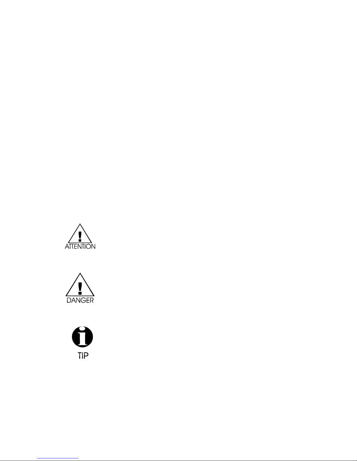
1.3 Safety symbols and the displays that have been used
This symbol indicates immediate danger to the life or health of
persons in the immediate vicinity of the machine.
Non-observance of dangers which are so indicated can have grave
consequences and can cause serious damage to health, or may even to
lead to deaths.
This symbol indicates that a potentially dangerous situation has
arisen.
Non-observance of dangers which are so indicated can lead to slight injuries
to persons or damage to equipment.
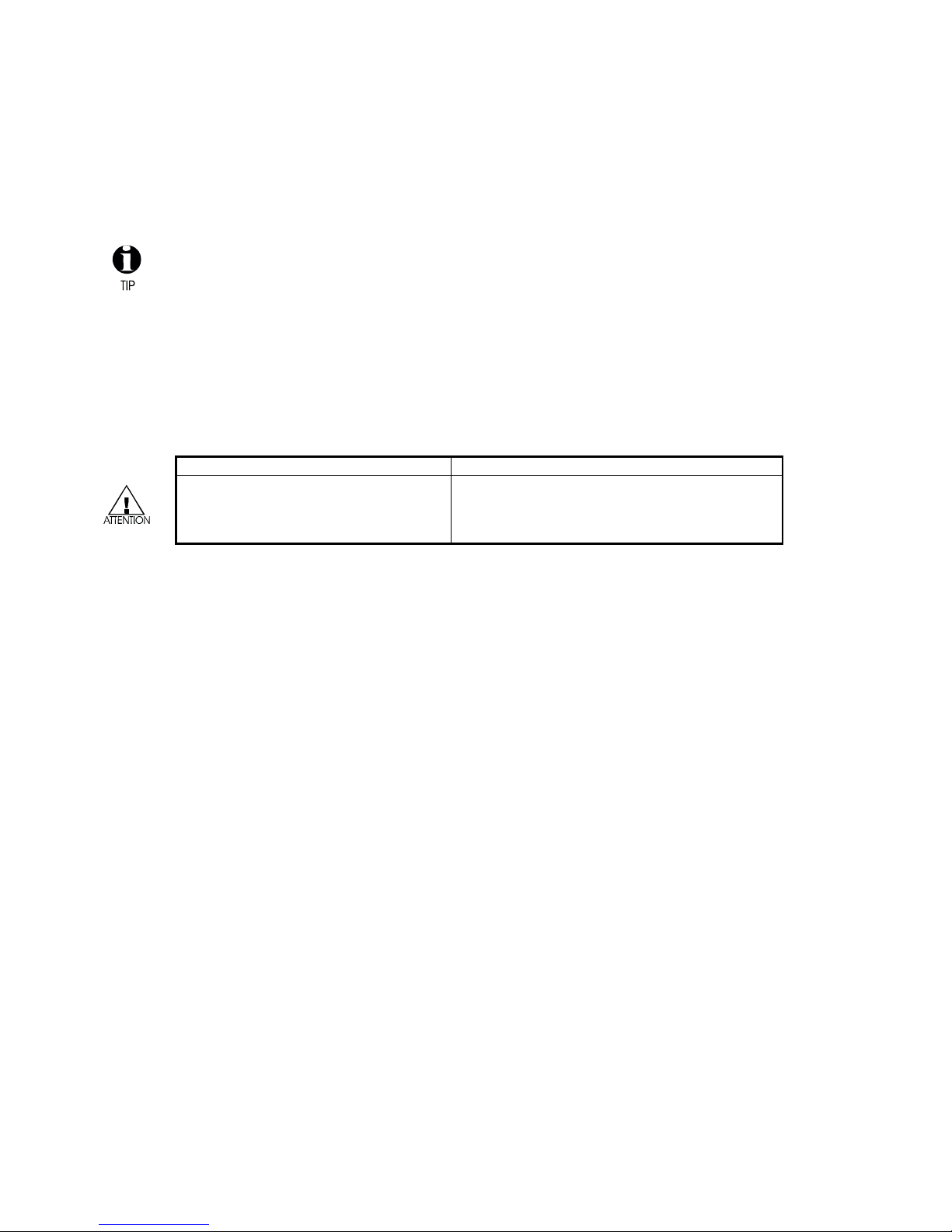
This symbol indicates that tips on how to use the machine or
particularly useful information are available.
These will help you to use all of the functions of the machine in an optimal
manner.
-
This symbol requires you to take action.
•
This sign serves as a symbol for listing items.

Safety Information
Hohner Maschinenbau GmbH HK 43/6 S
7
1.4 Obligation and liability
The 43/6 S Stitching Head has been built according to state-of-the art technology under
observance of all the recognised safety regulations. However, dangers to life and limb of the user
or third parties and damage to the system or other material assets can still occur during use.
The stitching head should only be used,
• for the purpose for which it was designed
• when it is in a perfect technical condition.
Faults which could reduce levels of safety when using the machine must be eliminated
immediately.
Warranties and liability on the part of the manufacturer are fundamentally covered by the
regulations laid down in our ”General sales and delivery conditions”.
Warranty claims will only be valid if the number label is affixed
(number label on stitching head housing).
1.5 Correct use
The Stitching Head 43/6 S is designed exclusively for binding brochures and leaflets or similar
items.
Any use of the machine contrary to that described above is forbidden, since incorrect use of the
machine can present a danger.
1.6 Organisational measures
The user of machine is required to provide the required personal safety equipment. All existing
safety devices should be checked regularly.
1.7 Safety and protective devices
All safety and protective devices must be correctly attached to the machine and should be in full
working order before every start-up of the machine and Stitching Head 43/6 S.
Safety and protective devices may only be removed:
• After the machine has come to a standstill and
• As security against the machine starting up again.
1.8 Non-formal safety measures
The Operating Manual must be kept so that it is permanently at hand at the machine with
Stitching Head 43/6 S. There are also generally valid local regulations concerning accident
prevention and environmental protection measures which should be made available and observed
in addition to those described in the Operating Instructions.
All safety and danger signs on the machine should be maintained in a legible condition and should
be renewed where necessary.
1.9 Staff training
Only trained and instructed personnel may install, operate, set and maintain the stitching head.

Safety Information
HK 43/6 S Hohner Maschinenbau GmbH
8
1.10 Parts of the equipment which are particularly dangerous
There is a risk of injury in the area of moving parts of the stitching head.
1.11 Maintenance and repair work, elimination of faults
Undertake the required setting, servicing and inspection work on schedule.
The machine may only be operated in cycle mode during all servicing, inspection and repair work
on the Stitching Head 43/6 S.
Always make absolutely sure that the machine is only being operated by one person in order
to avoid any influence to the machine by any other persons.
1.12 Structural modifications to the stitching head
Changes to the stitching head, additions or modifications may only be undertaken with the
manufacturer's permission.
1.13 Cleaning the machine and the disposal of waste products
The functionality of the stitching head and perfect processing of the product can only be
guaranteed over a prolonged period of time if the stitching head is regularly cleaned and
maintained in accordance with the standard methods of mechanical engineering.
In this regard, particular attention should be paid to the regular removal of trimmed paper
residue and paper dust, as these can result in jamming of the stitching head or increased
wear.
Substances and materials used (e.g. solvents and lubricants) must be handled correctly and
disposed of in an environmentally friendly manner.

Safety Information
Hohner Maschinenbau GmbH HK 43/6 S
9
Description of the Stitching Head
HK 43/6 S Hohner Maschinenbau GmbH
10
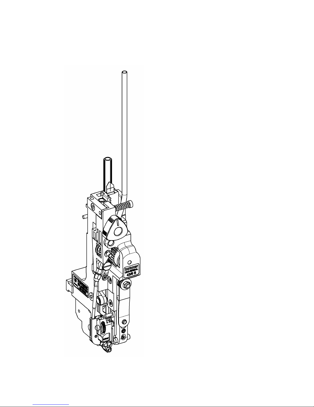
2 Description of the Stitching Head
Fig. 1
Description of the Stitching Head
Hohner Maschinenbau GmbH HK 43/6 S
11
2.1 General overview
- Fig. 1 -
2.2 Conformity
The Stitching Head 43/6 S conforms to the following guidelines and standards:
- Machine Guideline (98/37/EEC)
- EN 1010-1:1998 (final draft version) and
EN 1010-4:1997 ”Machine safety – safety requirements in connection with the design and
manufacture of printing and paper processing machines”, ”Part 1: General requirements” and
”Part 4: Bookbinding, paper processing and paper finishing machines”.
- This Operating Manual takes account of DIN EN 292, machine safety, basic terminology, general
principles of design.
2.3 Marking and type plate
The type plate is located at the front of the stitching head.
2.4 Technical data
Net weight of the stitching head 1,5 kg / 3.31 lbs
Quality of the stitching wire Only use perfect quality classes, in normal or
steel strength as required. Pay attention to
abrasion resistance, as heavy abrasion will clog
the wire-guidance parts.
Description of the Stitching Head
HK 43/6 S Hohner Maschinenbau GmbH
12
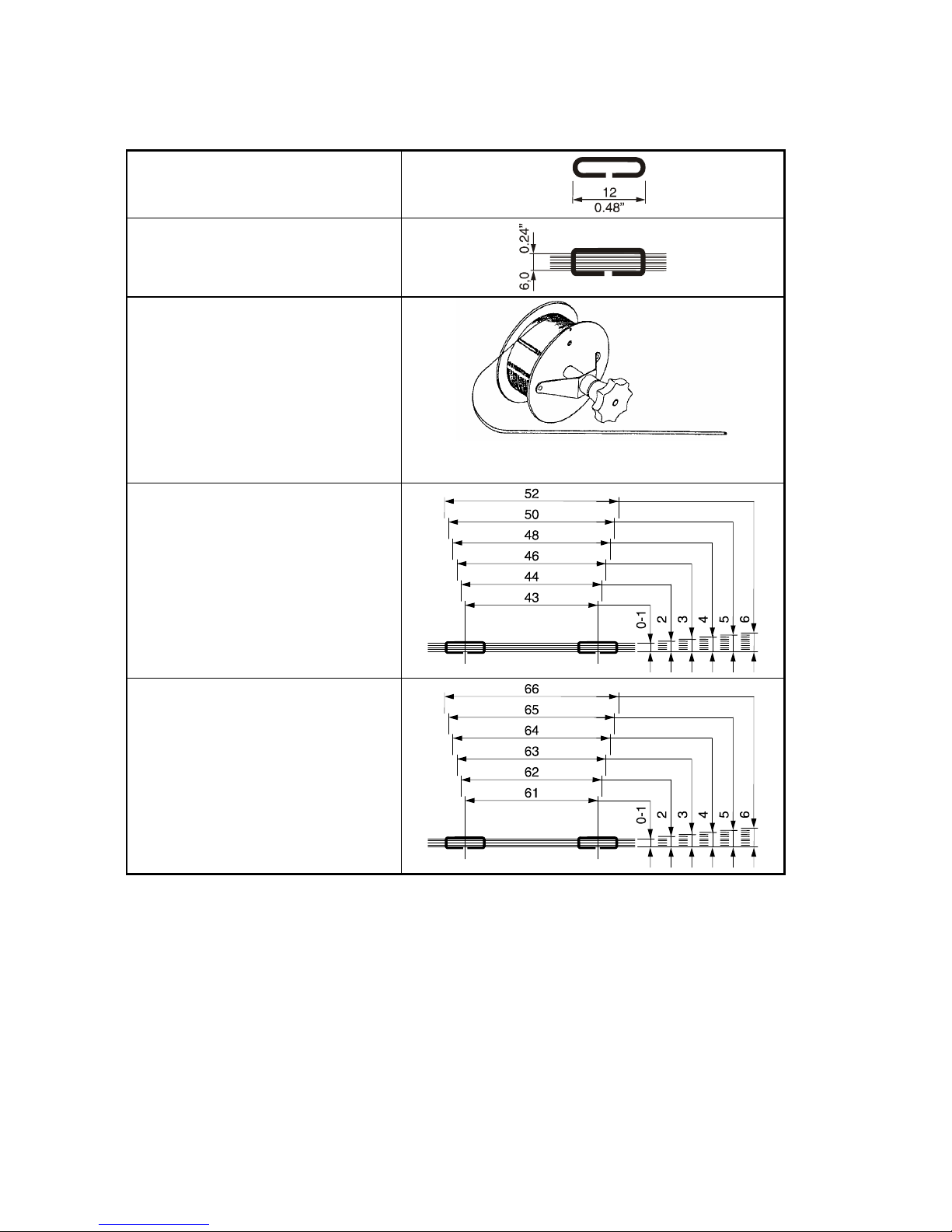
2.4.1 Normal stitch
Wire stitch dimensions
Max. stitch thickness
Stitching wire coil
No. 24 - 26
Ø 0.60 - 0.50 mm
(Ø 0.024 - 0.020 in.)
or:
Stitching wire coil
No. 26 - 28
Ø 0.50 - 0.40 mm
(Ø 0.020 - 0.016 in.)
Possible distances between wire
stitches and stitch thicknesses in mm
With holding down device
Description of the Stitching Head
Hohner Maschinenbau GmbH HK 43/6 S
13
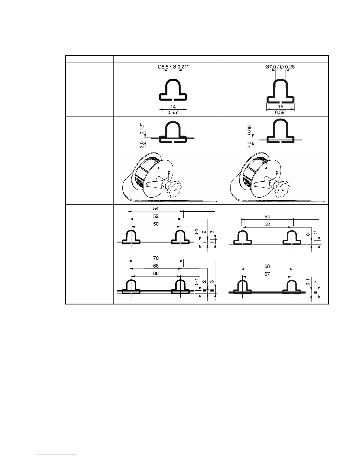
2.4.2 Loop stitch
Standard - L6 - - L8 Wire stitch
dimensions
Max. stitch
thickness
Stitching wire coil:
No. 24 - 26
Ø 0.60 - 0.50 mm
Ø 0.024 - 0.020
in.
Possible
distances
between wire
stitches and stitch
thicknesses in
mm
With holding
down device
Description of the Stitching Head
HK 43/6 S Hohner Maschinenbau GmbH
14
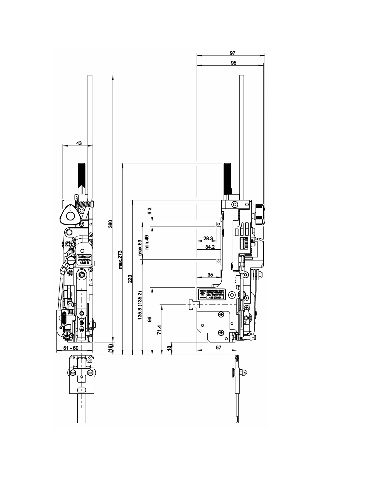
Fig. 2
Stroke

Description of the Stitching Head
Hohner Maschinenbau GmbH HK 43/6 S
15
Fig. 3
2.5 Dimensional sheet
- Fig. 2 , Fig. 3-
2.6 Outfitting of the stitching head
2.6.1 Basic features
The stitching head is delivered with the following accessories:
DESIGNATION ORDER NUMBER
Clincher box setting gauge 31 64 448
Torx screwdriver T10 46 00 044
Torx screwdriver T20 46 00 045
Allen key with T-handle SW4 x 70 / SW4-150 46 64 098 / 46 00 033
Adjusting handle 94 64 115
Wire guide, complete according to machine manufacturer
Clincher box, complete according to machine manufacturer
Stroke
Middle of Staple
Stroke
Operation
HK 43/6 S Hohner Maschinenbau GmbH
16
3 Operation
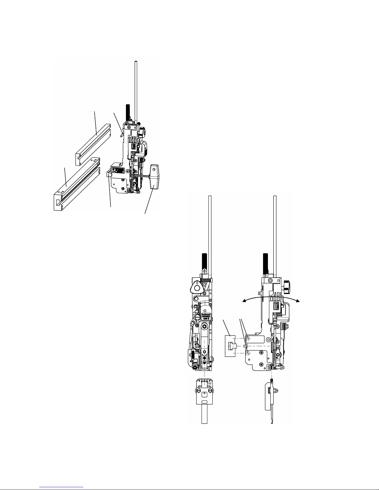
Fig. 4
Fig. 5
a
e
d
c
b
f
b
Middle of staple

Operation
Hohner Maschinenbau GmbH HK 43/6 S
17
3.1 Installation of the stitching head
3.1.1 Clamping the stitching head
- Fig. 4 -
The stitching head is held by a tenon block which is inserted into the stitching head mounting on
the machine.
- Unscrew tenon block from the stitching head with Allen key SW4 e.
- Introduce tenon block laterally into the stitching head mounting b.
- Insert stitching head into stitching head mounting, so that the driver lug c can be inserted into
the stroke bar d and the tenon block fits into the stitching head.
- Fix the stitching head by tightening the tenon block in the stitching head mounting using the Allen
key e.
3.1.1.1 Lateral adjustment of the stitching head
- Fig. 4, Fig. 5 -
The center of the wire formed parts within the stitching head must be set to the desired stitching
position for the wire stitch by lateral adjustment.
- Loosen the tenon block a with the Allen key e.
- Move the stitching head sideways, until the desired position is reached.
- Fix the tenon block in the stitching head mounting b with the Allen key.
3.1.1.2 Front adjustment of the stitching head
- Fig. 5 -
The lifting movement of the wire formed parts must drive the stitch accurately into the clincher box
forming gap. (Cf. Chap. 3.1.4). If the center of the wire stitch is located too far in front of or behind
the clincher box, or if the lifting movement is not precisely aligned with the clincher box, this can be
corrected by adjusting the set screws f on the stitching head.
- Remove stitching head.
- Adjust set screws f.
- Fit stitching head.
 Loading...