

Page 1
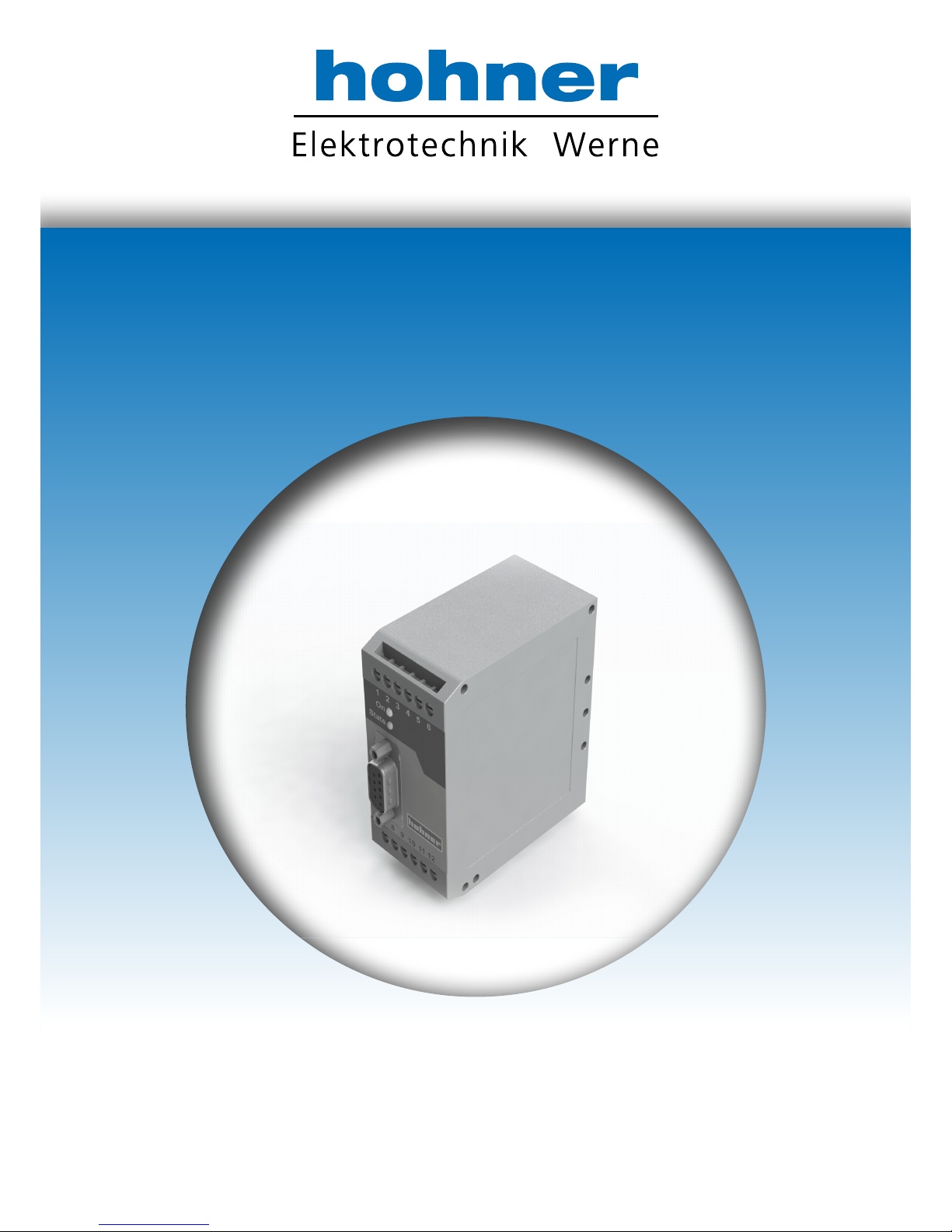
Operating Manual
Signal converter for frequency -analog / serial
FU 252
Your partner for standard and special designs
- precise, reliable and fast -
Page 2
Hohner Elektrotechnik GmbH
Gewerbehof 1
59368 Werne
Phone +49 - 2389 - 9878-0
Fax +49 - 2389 - 9878-27
E-Mail [email protected]
Web www.hohner-elektrotechnik.de
Operating Manual
FU 252
Signal converter for frequency - analog / serial
Product features:
Input frequency range from 0.1 Hz to 1 MHz for full scale analog output
Conversion time only 1 ms. (f > 2 kHz)
Analog output with +/- 10 V or 0 resp. 4 to 20 mA
Polarity of analog signal changes with change of the direction of rotation
Suitable for conversion of quadrature signals (A/B) as well as single-channel
signals, with all HTL or TTL or RS422 formats and levels
Suitable for conversion of the sum, the difference or the ratio of two frequencies
RS232 or RS485 interface for serial readout of the input frequencies
Programmable digital filters and programmable linearization curves
Easy to set up by simple TEACH procedure, or by PC operator software
www.hohner-elektrotechnik.de 2
Page 3
Table of Contents
1. SAFETY INSTRUCTIONS AND RESPONSIBILITY .......................................................................4
1.1. General Safety Instructions ...................................................................................... 4
1.2. Use according to the intended purpose ................................................................... 4
1.3. Installation................................................................................................................ 5
1.4. Cleaning, Maintenance and Service Notes ............................................................. 5
2. COMPATIBILITY HINT ..............................................................................................................6
3. INTRODUCTION .......................................................................................................................7
3.1. Impulse input formats and input levels .................................................................... 7
3.2. Operating range ........................................................................................................ 8
3.3. Suitable encoders and sensors ................................................................................ 8
4. TERMINAL ASSIGNMENTS AND CONNECTIONS ....................................................................9
4.1. Example for use of TTL encoders ............................................................................. 9
4.2. Example for use of HTL encoders ........................................................................... 10
4.3. Proximity switches, photocells etc. ........................................................................ 10
4.4. Analog output ......................................................................................................... 10
4.5. Serial interface ....................................................................................................... 11
5. DIL SWITCH SETTINGS .......................................................................................................... 12
5.1. Basic mode of operation ........................................................................................ 12
5.2. Impulse levels and symmetric / asymmetric input formats ................................... 13
5.3. Analog output format ............................................................................................. 14
5.4. Selecting the RS232 or the RS485 serial interface ............................................... 15
5.5. Teach function, Test function, loading of default settings .................................... 15
6. COMMISSIONING ................................................................................................................. 16
6.1. Conversion of one only frequency (single or dual channel with direction signal) . 17
6.2. Conversion and combination of two independent frequencies ............................ 17
7. PC SETUP VIA OPERATOR SOFTWARE OS3.X ........................................................................ 18
8. PARAMETER DESCRIPTION ................................................................................................... 20
9. FREE PROGRAMMABLE LINEARIZATION ............................................................................... 27
10. MONITOR FUNCTIONS .......................................................................................................... 29
11. DATA READOUT VIA SERIAL INTERFACE ............................................................................... 31
12. DIMENSIONS ........................................................................................................................ 32
13. TECHNICAL SPECIFICATIONS ................................................................................................ 33
14. INTERNAL REGISTERS AND SERIAL CODES .......................................................................... 34
15. COMMISSIONING FORM ....................................................................................................... 36
www.hohner-elektrotechnik.de 3
Page 4
1. Safety Instructions and Responsibility
1.1. General Safety Instructions
This operation manual is a significant component of the unit and includes important rules and
hints about the installation, function and usage. Non-observance can result in damage and/or
impairment of the functions to the unit or the machine or even in injury to persons using the
equipment!
Please read the following instructions carefully before operating the device and observe all
safety and warning instructions! Keep the manual for later use.
A pertinent qualification of the respective staff is a fundamental requirement in order to use
these manual. The unit must be installed, connected and put into operation by a qualified
electrician.
Liability exclusion: The manufacturer is not liable for personal injury and/or damage to property
and for consequential damage, due to incorrect handling, installation and operation. Further
claims, due to errors in the operation manual as well as misinterpretations are excluded from
liability.
In addition the manufacturer reserve the right to modify the hardware, software or operation
manual at any time and without prior notice. Therefore, there might be minor differences
between the unit and the descriptions in operation manual.
The raiser respectively positioner is exclusively responsible for the safety of the system and
equipment where the unit will be integrated.
During installation or maintenance all general and also all country- and application-specific
safety rules and standards must be observed.
If the device is used in processes, where a failure or faulty operation could damage the system
or injure persons, appropriate precautions to avoid such consequences must be taken.
1.2. Use according to the intended purpose
The unit is intended exclusively for use in industrial machines, constructions and systems. Nonconforming usage does not correspond to the provisions and lies within the sole responsibility
of the user. The manufacturer is not liable for damages which has arisen through unsuitable
and improper use.
Please note that device may only be installed in proper form and used in a technically perfect
condition and in accordance to the Technical Specifications (see chapter 13). The device is not
suitable for operation in explosion-proof areas or areas which are excluded by the EN 61010-1
standard.
www.hohner-elektrotechnik.de 4
Page 5
1.3. Installation
The device is only allowed to be installed and operated within the permissible temperature
range. Please ensure an adequate ventilation and avoid all direct contact between the device
and hot or aggressive gases and liquids.
Before installation or maintenance, the unit must be disconnected from all voltage-sources.
Further it must be ensured that no danger can arise by touching the disconnected voltagesources.
Devices which are supplied by AC-voltages, must be connected exclusively by switches,
respectively circuit-breakers with the low voltage network. The switch or circuit-breaker must
be placed as near as possible to the device and further indicated as separator.
Incoming as well as outgoing wires and wires for extra low voltages (ELV) must be separated
from dangerous electrical cables (SELV circuits) by using a double resp. increased isolation.
All selected wires and isolations must be conform to the provided voltage- and temperatureranges. Further all country- and application-specific standards, which are relevant for structure,
form and quality of the wires, must be ensured. Indications about the permissible wire crosssections for wiring are described in the Technical Specifications (see chapter 13).
Before first start-up it must be ensured that all connections and wires are firmly seated and
secured in the screw terminals. All (inclusively unused) terminals must be fastened by turning
the relevant screws clockwise up to the stop.
Overvoltages at the connections must be limited to values in accordance to the overvoltage
category II.
For placement, wiring, environmental conditions as well as shielding and earthing/grounding of
the supply lines the general standards of industrial automation industry and the specific shielding
instructions of the manufacturer are valid.
1.4. Cleaning, Maintenance and Service Notes
To clean the front of the unit please use only a slightly damp (not wet!), soft cloth. For the rear
no cleaning is necessary. For an unscheduled, individual cleaning of the rear the maintenance
staff or assembler is self-responsible.
During normal operation no maintenance is necessary. In case of unexpected problems, failures
or malfunctions the device must be shipped for back to the manufacturer for checking,
adjustment and reparation (if necessary). Unauthorized opening and repairing can have
negative effects or failures to the protection-measures of the unit.
www.hohner-elektrotechnik.de 5
Page 6
2. Compatibility Hint
This product is a successor model of the thousandfold proven converter type FU251. The new
product is suitable for a 100% replacement of the previous model, however some differences
must be observed with DIL switch settings and parameter settings.
S
ome essential advantages of FU252 compared to FU251 are:
Maximum frequency 1 MHz (instead of 500 kHz)
Total conversion time in-out = 1 ms (this was no more assured with
FU251 after the modifications necessary for RoHS conformity)
Capability to accept even single-ended TTL input signals
(i.e. TTL input A only without inverted TTL signal /A)
The setting of the analog format (+/-10 V, 0 … 10 V or 0/4 … 20 mA)
can be done by a supplementary DIL switch (no more PC required)
Enhanced auxiliary output 5 V / 250 mA for encoder supply
www.hohner-elektrotechnik.de 6
Page 7
3. Introduction
FU 252 is a small and low-cost, but highly performing converter for industrial applications,
where one frequency or two different frequencies need to be converted into an Analog signal or
a serial data format. The unit has been designed as a compact module with 12 screw terminals
and a 9-position SUB-D connector (female). The housing is suitable for standard DIN rail
mounting.
3.1. Impulse input formats and input levels
The input site provides channels A and B and also the inverted lines /A and /B. All inputs are
designed for use with either HTL level or TTL level, with either single-ended format or
differential format (RS422).
The unit can convert the following formats to Analog and serial:
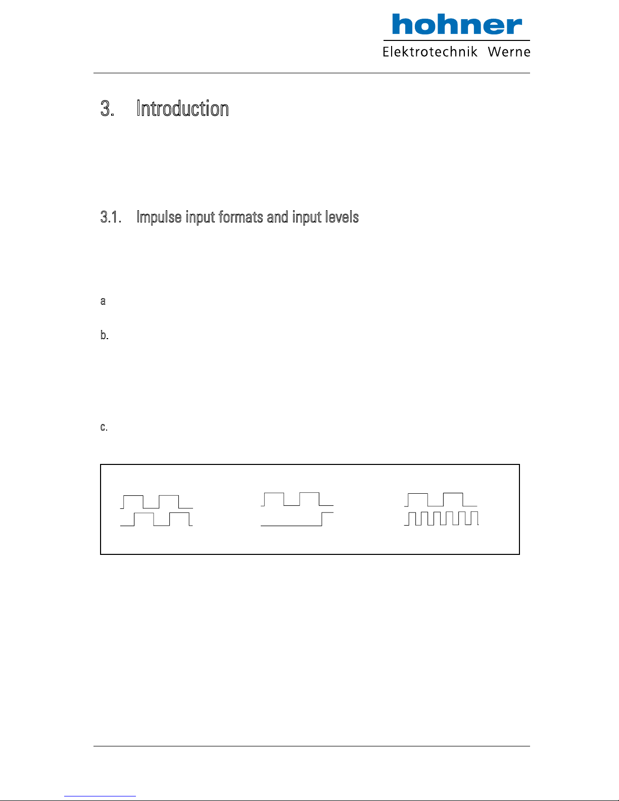
a
. Quadrature signals with a 90 phase displacement. Polarity of the Analog output and sign
of the serial data depend on the direction given by the A/B phase.
b. Single channel impulses on channel A. Input B sets the polarity of the output (LOW =
negative, HIGH = positive). In case of open (unconnected) inputs, please note:
Open NPN inputs are evaluated as HIGH state
Open PNP inputs are evaluated as LOW state
Open RS422 inputs may cause problems, therefore please set unused inputs to HTL by
means of the appropriate DIL switch
c. Fully independent frequencies on both channels A and B. The output signal can represent
the sum, the difference, the product or the ratio of the two input frequencies.
A
B
A
B
A
B
A and B, quadrature 90°
A=impulse, B=static polarity select
A and B: independant frequencies
a. b.
c.
+
-
www.hohner-elektrotechnik.de 7
Page 8
3.2. Operating range
The full scale frequency (i.e. the input frequency where the Analog output reaches 10 V or
20 mA) can be set in a range from –1 MHz to +1 MHz. The operating range of the unit can be
assigned to any frequency window inside this frequency range.
A “zero output frequency” can be set to guarantee defined operation of the converter with low
input frequencies.
For applications with unstable input frequencies, the unit provides programmable digital filters
for smoothing of the output signal.
3.3. Suitable encoders and sensors
The FU252 converter can accept the following impulse sources:
Quadrature encoders with HTL level output (10 – 30 V) and either PNP or NPN or Push-
Pull or NAMUR characteristics, using A and B outputs wit 90° displacement
Single channel impulse sources like proximity switches or photocells, providing HTL
level at PNP or NPN or Namur characteristics
TTL / RS422 quadrature encoders with output lines A, /A ,B and /B
Symmetric single channel sources with TTL / RS422 output, providing differential
signals (e.g. A and /A)
Asymmetric single channel sources wit TTL level (without inverted signals, e.g. A only)
In general, HTL encoders will be supplied from the same source as the converter itself.
For supply of TTL encoders, the unit provides an auxiliary output of 5.5 volts
(stabilized, max. 250 mA).
www.hohner-elektrotechnik.de 8
Page 9
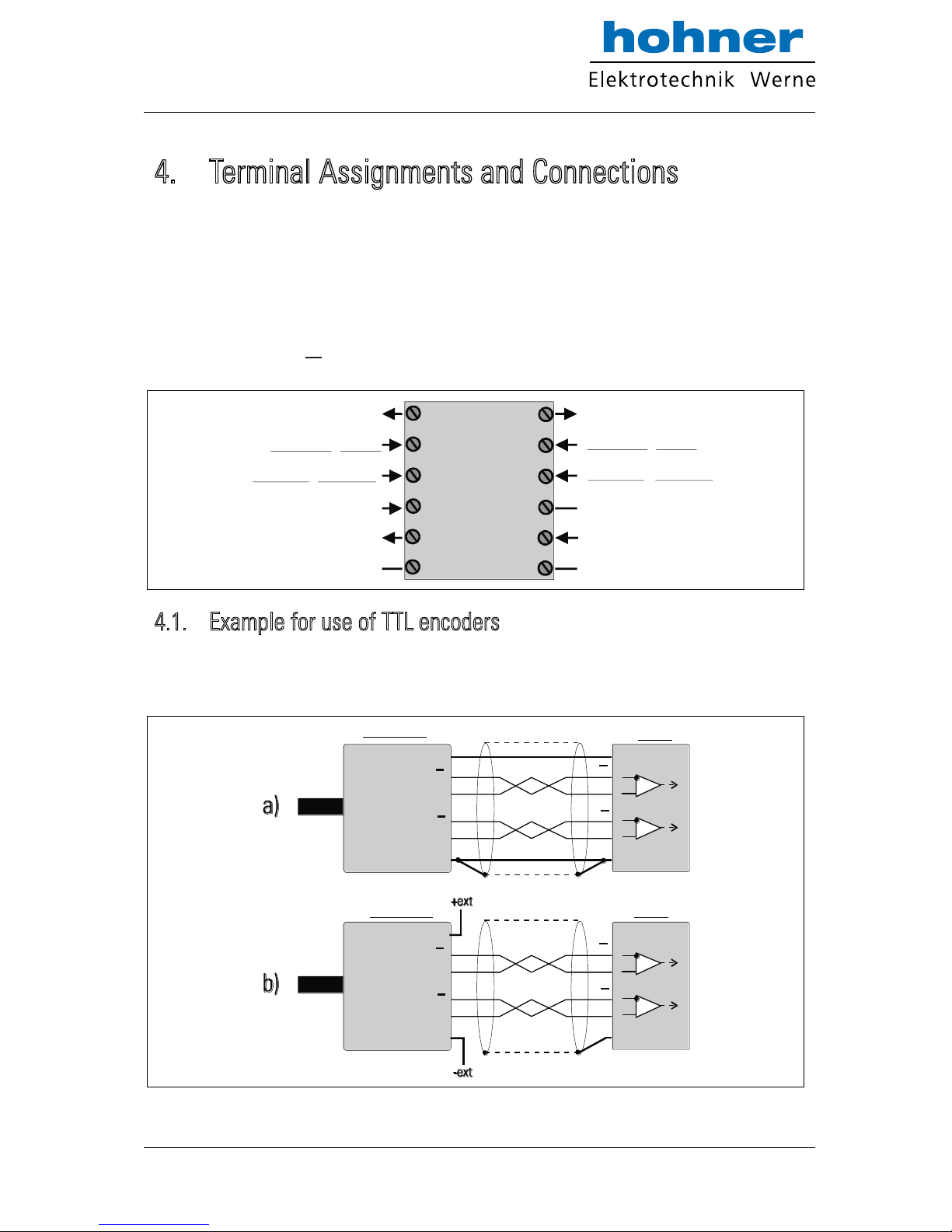
4. Terminal Assignments and Connections
We recommend connecting the Minus wire of the power supply to earth potential.
Please observe that, under poor earthing and grounding conditions, multiple earth connections
of screens and GND terminals may cause severe problems. In such cases it may be better to
have only one central earthing point for the whole system.
GND terminals 4, 6 and 12 are connected internally.
Under nominal conditions the current consumption of the unit is approx. 70 mA (aux. output
unloaded, see section 13 “Technical Specifications”). Lower input voltage and load of the aux.
output will increase the consumption accordingly.
1 2 3 4 5 6
7 8 9 10 11 12
Voltage output +/-10V
TTL: input /B HTL: n.c.
TTL: input B HTL: input B
GND ( - ) for analogue signals
Supply +18...30 VDC
(typ. 70 mA)
Current output 0-20mA / 4-20mA
TTL: input /A HTL: n.c.
TTL: input A HTL: input A
Control
Aux. output 5.5V
(max. 250 mA)
GND ( - )
GND ( - )
FU 252
4.1. Example for use of TTL encoders
If applicable, the encoder can be supplied from the FU252 converter. Where the encoder is
already supplied from a remote source, we recommend fully differential operation, with no
GND connection between encoder and converter (see figures a. and b.)
8
9
2
3
11 (+5.5V)
12 (GND)
+
-
TTL encoder
FU 252
Screen
A
A
B
B
A
A
B
B
8
9
2
3
11 (+5.5V)
12 (GND)
+
-
Screen
A
A
B
B
A
A
B
B
TTL encoder FU 252
www.hohner-elektrotechnik.de 9
Page 10
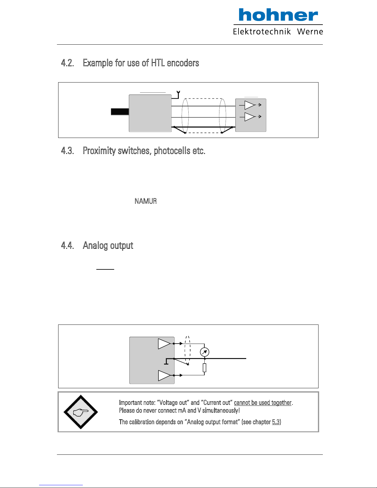
4.2. Example for use of HTL encoders
The encoder may be supplied from the same source as the converter, or from another source.
9
3
12 (GND)
GND
HTL encoder
FU 252
Screen
+24V
+
A
B
4.3. Proximity switches, photocells etc.
These connections are fully similar to a HTL incremental encoder. With single channel
operation, input B remains unconnected or can be used to select the output polarity. With use
of two independent frequencies for forming sum, difference or ratio, input B is used for the
second input frequency.
To use sensors with 2-wire NAMUR characteristics:
set the inputs to HTL and NPN
connect the positive wire of the sensor to the corresponding input and the negative wire
to GND.
4.4. Analog output
The unit provides a +/-10V voltage output and a 0 - 20mA / 4 – 20 mA current output at a
resolution of 14 bits, i.e. the voltage output operates in steps of 1.25 mV and the current output
operates in steps of 2.5 µA.
The nominal load of the voltage output is 2 mA and the current output accepts loads between
zero and 270 ohms.
The Analog ground uses a separate terminal, which however internally is connected to the GND
potential of the power supply.
GND
4
1
7
+/- 10V
20 mA
(R = 0 - 270 ohms)
(Imax = 2 mA)
Screen
Voltage out
Current out
Important note: “Voltage out” and “Current out” cannot be used together.
Please do never connect mA and V simultaneously!
The calibration depends on “Analog output format” (see chapter 5.3)
www.hohner-elektrotechnik.de 10
Page 11
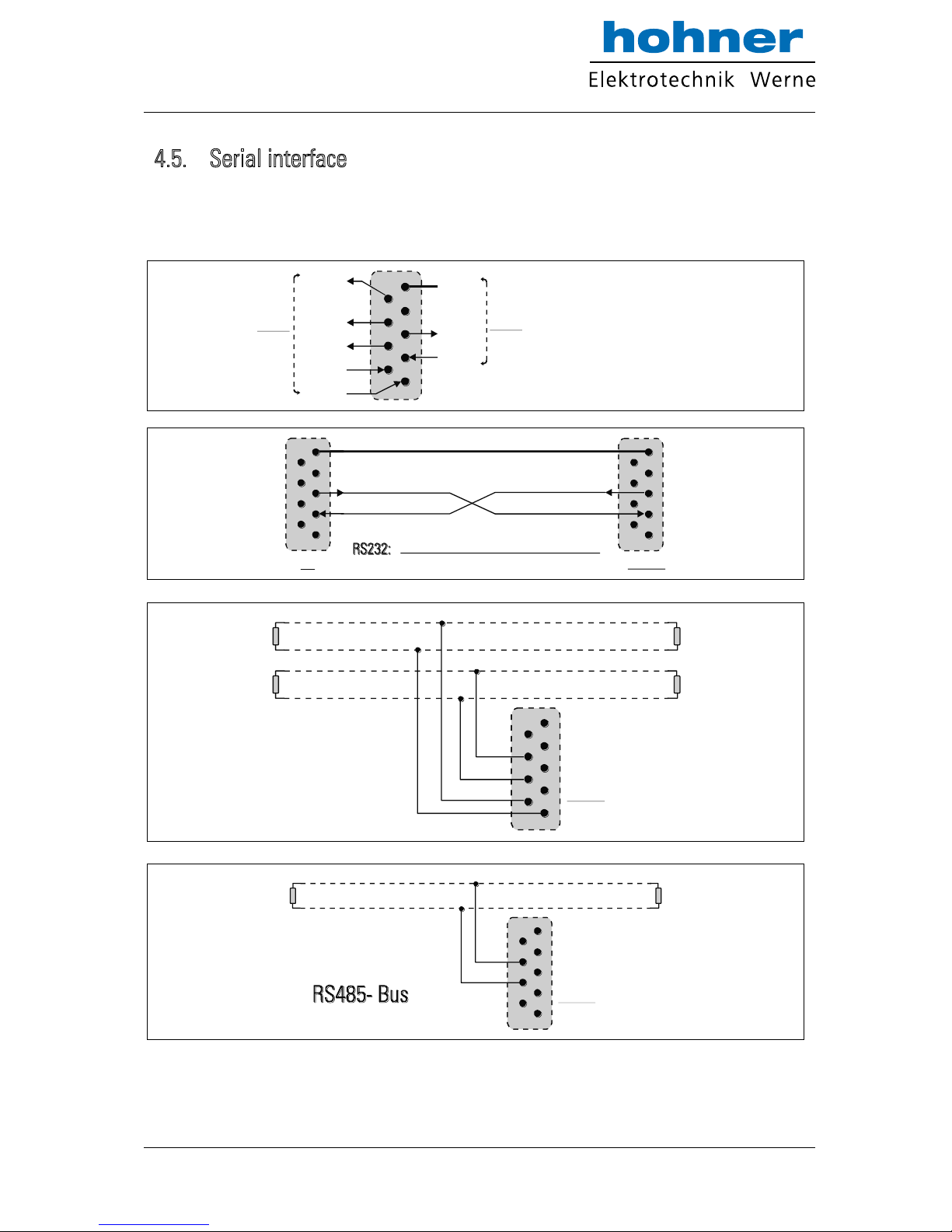
4.5. Serial interface
The unit provides selectively a RS232 resp. RS485 interface, however only one of the two can
be used at a time. Serial communication allows to read out conversion results and to set
parameters and variables by PC, according to need.
5
4
3
2
1
9
8
7
6
GND int.
TxD
RxD
RS232
+5V
T+
T-
R+
R-
RS485
Sub-D-9 (female on unit site)
5
4
3
2
1
9
8 7
6
5
4
3
2
1
9
8 7
6
5
4 3
2
1
9
8 7
6
5
4 3
2
1
9
8 7
6
GND
TxD
RxD
PC
FU 252
Please connect only pins 2, 3 and 5 !
5
4
3
2
1
9
8 7
6
5
4
3
2
1
9
8 7
6
T+
T-
120 Ohms 120 Ohms
RS485- Bus
( 4- wire )
FU 252
120 Ohms 120 Ohms
R+
R-
T+
T-
R+
R-
5
4 3
2
1
9
8 7
6
5
4 3
2
1
9
8 7
6
T+
T-
120 Ohms
120 Ohms
( 2- wire )
FU 252
www.hohner-elektrotechnik.de 11
Page 12
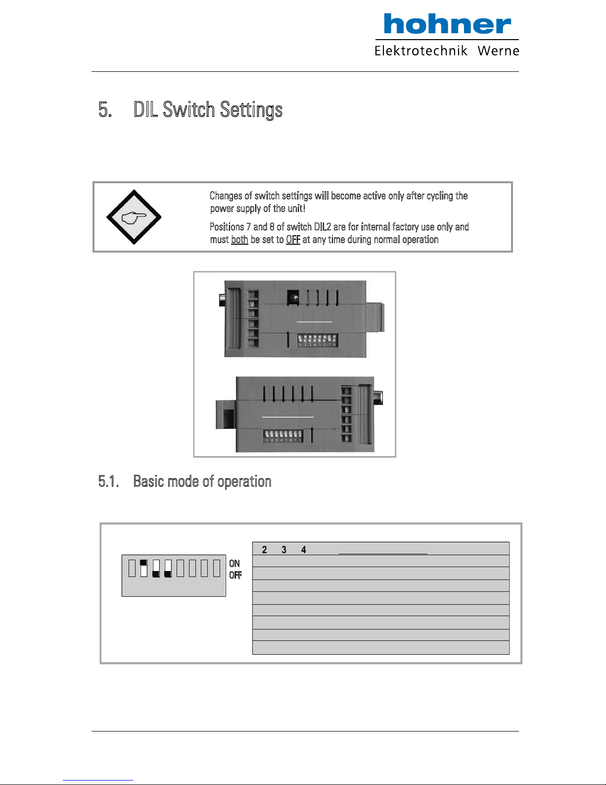
5. DIL Switch Settings
There is one 8-position switch located on the top side (DIL1), and another 8-position switch is
located on the bottom side of the unit (DIL2). These switches provide major settings of the
desired properties of the unit.
Changes of switch settings will become active only after cycling the
power supply of the unit!
Positions 7 and 8 of switch DIL2 are for internal factory use only and
must both be set to OFF at any time during normal operation
5.1. Basic mode of operation
Positions 2, 3 and 4 of switch DIL1 on the top side allow setting the following operation modes:
1 2 3 4 5 6 7 8
on on on
on on off
on off on
on off off
off on on
off on off
off off on
off off off
Mode of operation
Channel A only
Ratio A : B
Sum A + B
Quadrature A / B / 90°
Channel B only
Product A x B
Difference A - B
A = impulse, B = direction / sign
DIL1
Setting example:
Quadrature input A / B / 90°
Top side
Sw i tc h DI L 1
Teach button
Bottom side
Swit ch DIL 2
www.hohner-elektrotechnik.de 12
Page 13
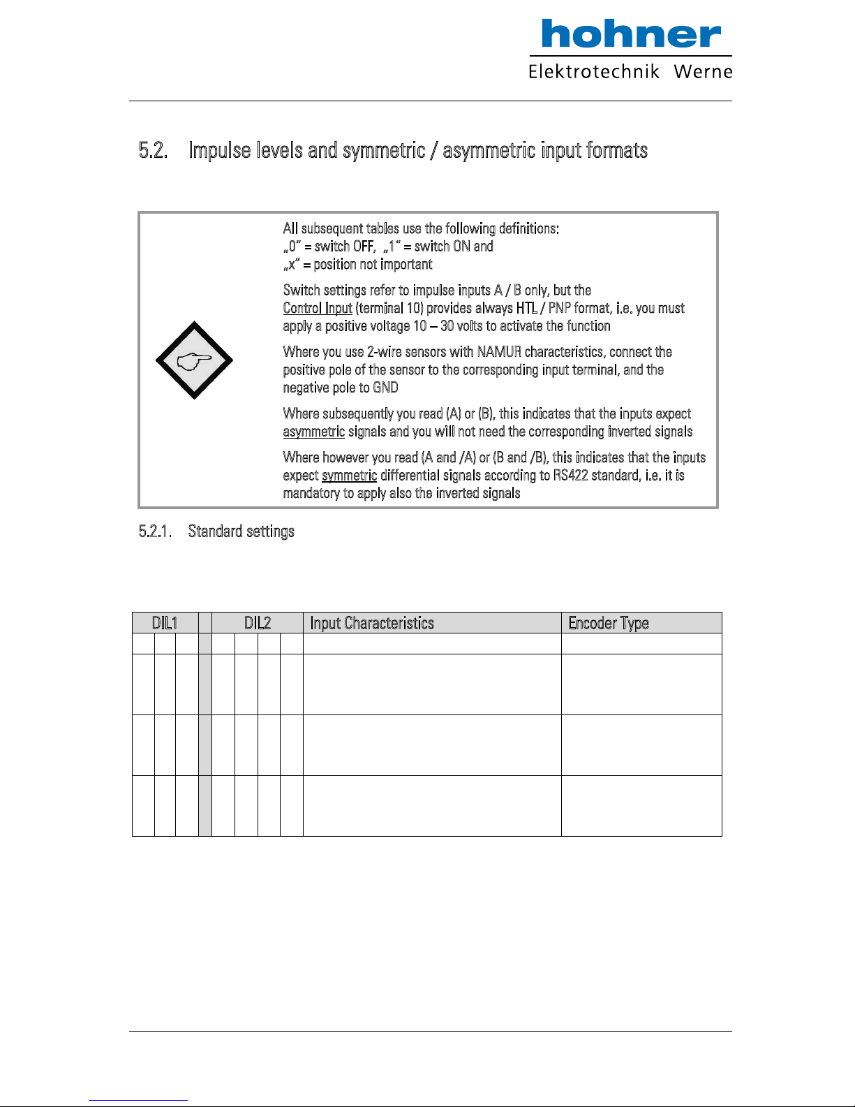
5.2. Impulse levels and symmetric / asymmetric input formats
Positions 5 and 7 of DIL1 together with positions 3 to 6 of DIL2 allow setting of all imaginable
combinations of levels and formats.
All subsequent tables use the following definitions:
„0“ = switch OFF, „1“ = switch ON and
„x“ = position not important
Switch settings refer to impulse inputs A / B only, but the
Control Input (terminal 10) provides always HTL / PNP format, i.e. you must
apply a positive voltage 10 – 30 volts to activate the function
Where you use 2-wire sensors with NAMUR characteristics, connect the
positive pole of the sensor to the corresponding input terminal, and the
n
egative pole to GND
Where subsequently you read (A) or (B), this indicates that the inputs expect
asymmetric signals and you will not need the corresponding inverted signals
Where however you read (A and /A) or (B and /B), this indicates that the inputs
expect symmetric differential signals according to RS422 standard, i.e. it is
mandatory to apply also the inverted signals
5.2.1. Standard settings
If you just use encoders or sensors according to common industrial standards, and if also all
input signals should have the same level, you just can use one of the following three standard
settings and do not need to consider all further alternatives of switch settings.
DIL1 DIL2
Input Characteristics
Encoder Type
5 6 7 3 4 5 6
0
0
0 0 0
0
Asymmetric HTL input (A, B),
10 - 30 V level, NPN (switching to -) or
Push-Pull or NAMUR characteristics
Standard HTL encoders,
Proximity switches,
Photo switches etc.
1
0
0 0 0
0
Asymmetric HTL input (A, B),
10 - 30 V level, PNP (switching to +) or
Push-Pull characteristics
PNP Proximity switches,
Photo switches etc.
0
1
0 0 0
0
Symmetric TTL signals or
RS422 signals (A, /A), (B, /B)
(differential, including inverted signal)
Standard TTL encoders
providing A, /A, B, /B
output channels
www.hohner-elektrotechnik.de 13
Page 14
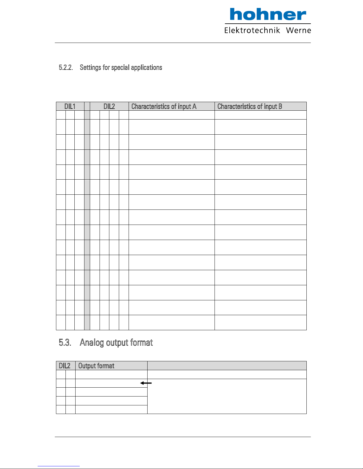
5
.2.2. Settings for special applications
Where you find that the standard settings shown before are not suitable for your application,
please go through the following setting options and find out the input levels and characteristics
you need.
DIL1 DIL2
Characteristics of input A
Characteristics of input B
5 6 7 3 4 5 6
x
x
0 0 0 1
TTL level (A)
TTL level (B)
x
x
0 0 1 0
HTL level (A and /A)
HTL level (B and /B)
x
x
0 0 1 1
TTL level (A)
TTL level (B and /B)
x
x
0 1 0 0
TTL level (A and /A)
TTL level (B)
x
x
0 1 0 1
HTL level NPN (A)
HTL level PNP (B)
x
x
0 1 1 0
HTL level NPN (A)
TTL level (B and /B)
x
x
0 1 1 1
HTL level NPN (A)
TTL level (B)
x
x
1 0 0 0
HTL level PNP (A)
TTL level (B and /B)
x
x
1 0 0 1
HTL level PNP (A)
TTL level (B)
x
x
1 0 1 0
HTL level PNP (A)
HTL level NPN (B)
x
x
1 0 1 1
TTL level (A and /A)
HTL level NPN (B)
x
x
1 1 0 0
TTL level (A)
HTL level NPN (B)
x
x
1 1 0 1
TTL level (A and /A)
HTL level PNP (B)
x
x
1 1 1 0
TTL level (A)
HTL level PNP (B)
5.3. Analog output format
The desired output format of the Analog output can be set by positions 1 and 2 of switch DIL2.
DIL2
Output format
1 2
0
0
Voltage 0 … +10 V
With this setting the format depends on the parameter „Analog
Mode“ which can be set by PC. Since the factory default setting
of parameter “Analog Mode” is “1”, the format will be a 0 …
+10 V output under default conditions.
0
1
Voltage +/- 10 V
1
0
Current 4 – 20 mA
1
1
Current 0 – 20 mA
www.hohner-elektrotechnik.de 14
Page 15
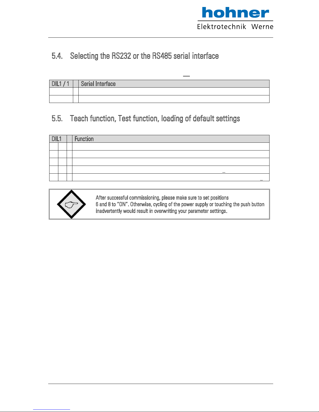
5.4. Selecting the RS232 or the RS485 serial interface
Position 1 of switch DIL1 selects between the RS232 interface and the RS485 interface. All
connection details have already been explained in section 4.5.
DIL1 / 1
Serial Interface
0
RS232 interface is active (RS485 is switched off)
1
RS485 interface is active (RS232 is switched off)
5.5. Teach function, Test function, loading of default settings
Positions 6 and 8 of switch DIL1 allow to set the following functions:
DIL1
Function
6 8
x
0
Unit returns to the factory default parameters after power-down
x
1
Unit always keeps the parameters according to customer setting
0
x
Push button and yellow LED operate in TEACH mode (see chapter 7)
1
x
Push button and yellow LED operate in TEST mode, Teach is disabled (see chapter 7)
After successful commissioning, please make sure to set positions
6 and 8 to “ON”. Otherwise, cycling of the power supply or touching the push button
inadvertently would result in overwriting your parameter settings.
www.hohner-elektrotechnik.de 15
Page 16
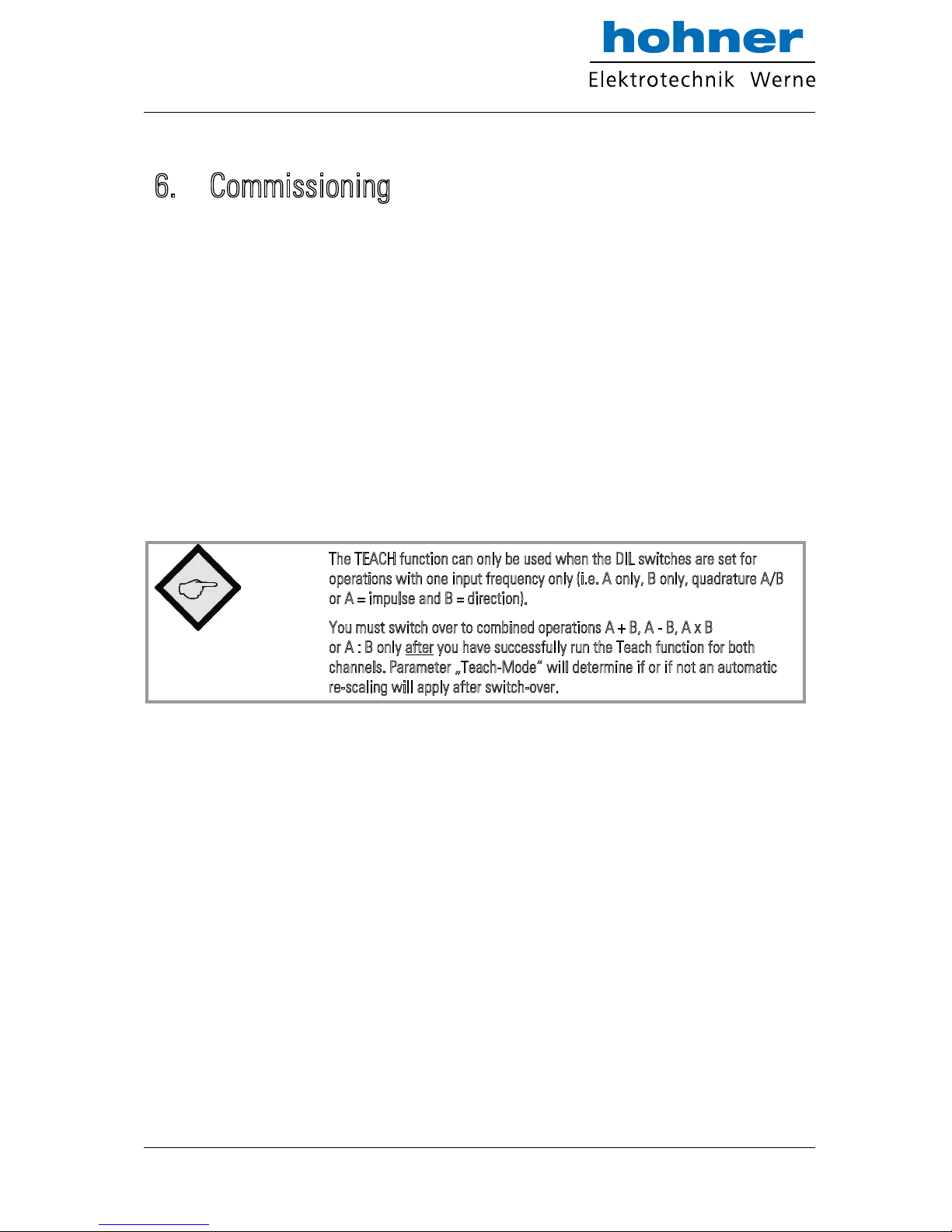
6. Commissioning
With all basic applications, you can use the Teach feature for commissioning of the unit.
Extended functions need a PC for setup and are described under section 7.
As a first step it is advisable to check the input frequencies by means of the LED marked
“Status”. DIL switch 6 must be set to ON for this test.
When you press the TEACH button one time, the yellow LED will be lit when the unit detects a
frequency on input A. The LED will be OFF when no input frequency can be detected.
When you press the TEACH button once more, you can also check input B (if applicable). With
all operation modes using two independent frequencies, again the yellow LED will be lit when
a frequency has been detected on input B.
With operation modes using input B to define the direction and polarity (quadrature or static),
the yellow LED will indicate that the actual input signals provide positive output (LED on) or
negative output (LED off). Where you like to get the other polarity, you must change the
information of direction on A/B inputs
The TEACH function can only be used when the DIL switches are set for
operations with one input frequency only (i.e. A only, B only, quadrature A/B
or A = impulse and B = direction).
You must switch over to combined operations A + B, A - B, A x B
or A : B only after you have successfully run the Teach function for both
channels. Parameter „Teach-Mode“ will determine if or if not an automatic
r
e-scaling will apply after switch-over.
www.hohner-elektrotechnik.de 16
Page 17
6.1. Conversion of one only frequency
(
single channel or dual channel with direction signal)
Make sure that the DIL switches are set according to the encoder you use, and that position 6
of switch DIL1 is OFF (Teach function active).
Self-test: Upon power up, both front LED’s must be lit first, and the yellow status LED must
switch off after the self-test has been concluded successfully (approx.1 s).
Scaling of the Analog output with use of the Teach function:
Press the Teach button one time. The status LED will blink in a slow sequence while the
unit waits for setting of the minimum frequency. Please make your encoder now generate
the frequency where you expect your Analog output to be zero (in general this will be 0 Hz
at standstill)
Press the Teach button again. This stores your minimum frequency definition, the LED will
blink in a fast sequence and the unit waits for setting of the maximum frequency. Please
move your encoder now at a speed where you expect full scale Analog output.
Press the teach button once more. This stores your maximum frequency definition and the
LED will switch off. After this Teach procedure, your Analog output is set to a 0 – 10 volts
range between the minimum and the maximum input frequency.
6.2. Conversion and combination of two independent
frequencies (A + B, A - B, A x B, A : B)
In principle, the Teach procedure is the same as described under 6.1. However, we must first
teach every of the two channels A and B separately.
Set the DIL switch to “Channel A only” (see 5.1) and teach the minimum and the maximum
frequency for channel A like shown before.
Now set the DIL switch to “Channel B only” and run the teach procedure for minimum and
maximum frequency of channel B.
Finally, set the DIL switch according to the combination of the frequencies that you desire.
The unit is able to automatically re-scale the output swing in a way that you receive full
scale output when the result of the A/B calculation reaches the maximum
(see parameter “Teach Mode”).
Please observe that minimum and maximum frequency settings for
i
nputs A and B must never be “0” when you intend to use the ratio
f
unction A : B !
www.hohner-elektrotechnik.de 17
Page 18
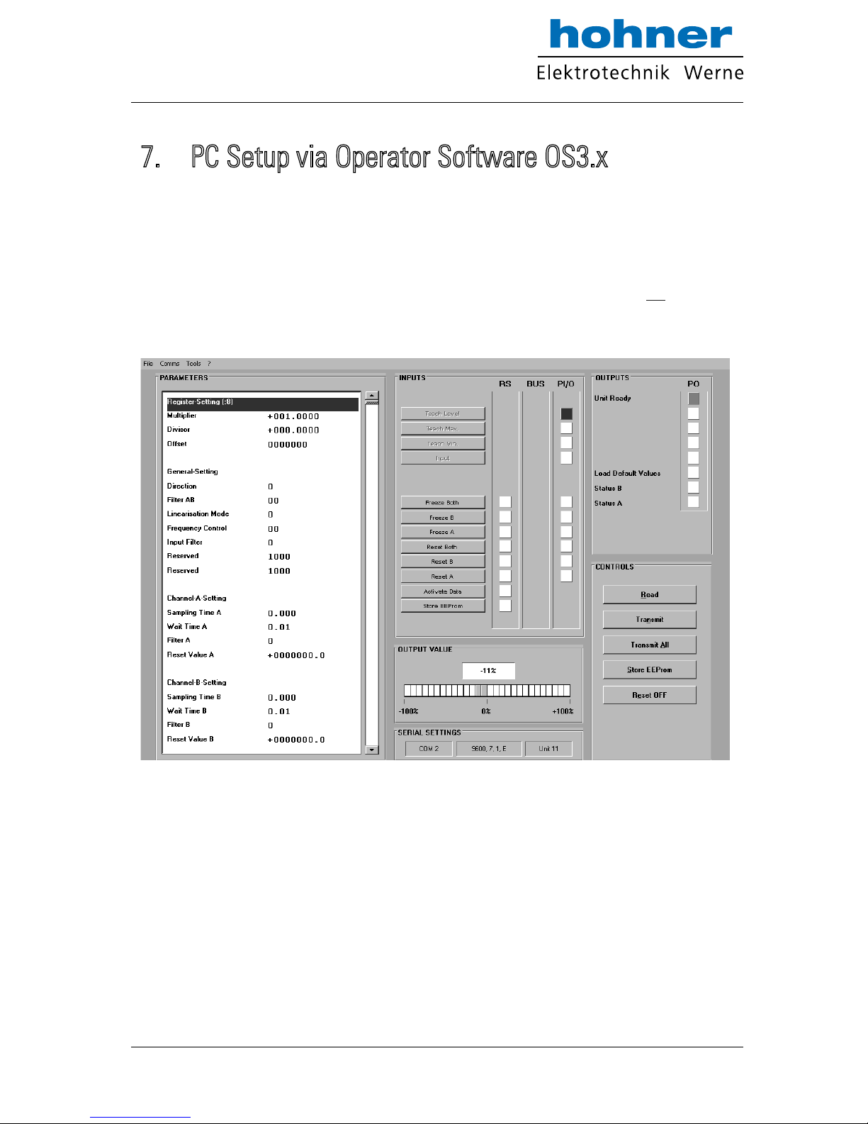
7. PC Setup via Operator Software OS3.x
You can apply the full set of functions when you use a PC and our operator software OS3.x for
setup of the unit (at this time the actual version is OS3.2).
You can download this software and full instructions, free of charge, from our homepage
Connect your PC to the converter, using a serial RS232 cable like shown in section 4.5 of this
manual. Make sure, the cable only uses pins 2, 3 and 5. Pins 2 and 3 must be crossed.
Run the OS3.x software and you will see the following screen:
In case your text and color fields remain empty and the headline says „OFFLINE“, you must
verify your DIL switch setting and the serial settings of the unit. To access serial settings,
please select „COMMS“ from the menu bar.
www.hohner-elektrotechnik.de 18
Page 19
Ex-factory, all motrona units use the following serial default settings:
Unit No. 11, Baud rate 9600, 1 start/ 7 data/ parity even/ 1 stop bit
If the serial settings of your unit should be unknown, you can run the „SCAN“ Function
from the „TOOLS“ menu to find out.
On the left side of your screen you find the Edit window with all parameters.
Under „INPUTS“ you find some soft keys allowing to switch ON or OFF of the Control
commands. Indicator boxes in the RS column signal if the corresponding command is set by
serial communication. Indicator boxes in the PI/O column indicate if the same command is set
by hardware input.
Under OUTPUTS you can get information about the state of the unit. The indicator boxes
„Status A“ and „Status B“ especially serve to check the input frequencies:
Status A will be lit while a frequency is detected on input A
(except with operating mode „B single“)
Status B will be lit while a frequency is detected on input B
(except with operating modes „A single“, „A/B_dir“ and „A/B_90“)
The color bar in the “Output Value” field indicates the actual percentage of the output
signal in a range of +/- 100 %.
The Control keys allow Read-out, Transmission and saving of parameter settings.
F
or enduring memorization of parameters entered by keypad, you should press
t
he ENTER key every time you have completed one line.
Optionally you can also use the soft keys „Transmit“ or „Transmit All“ for
temporary storage of your last setting or all previous settings (storage until next
power-down), and finally use the „Store EEProm“ key when you like to have an
enduring storage of all settings transmitted before.
www.hohner-elektrotechnik.de 19
Page 20
8. Parameter Description
Parameter
Description
Register Setting (.8):
Multiplier
Divisor
Offset
These operands allow converting the result to the desired engineering
units.
T
his conversion affects the numeric value for serial read out from
r
egister (:8) only, but not the scaling of the Analog output.
With settings Multiplier = 1,0000
Divisor = 1,0000
Offset = 00000
the readout from register < :8 > equals to the percental result
(xxx.xxx%) where 100,000% has been defined by the TEACH
minimum and TEACH maximum settings
Offset
Read-out from (:8)
=
Measuring result in % of full scale
x
Multiplier
Divisor
+
When you set “Divisor” to 0, this will completely skip all calculations.
T
his step is advisable when you need very fast response with the shortest
c
onversion time possible.
General Setting:
Direction
Filter A/B
Linearisation Mode
This parameter allows inversion of the polarity of the Analog output.
(Important only with operating modes A/B (2x90) or A = Impulse and B
= direction.
0
= no inversion
1
= output inverted
Digital filter for smoothing the Analog output with combined modes
(calculations from A and B)
0
0 = Filter off (immediate response to changes of the input signal)
0
1 = Filter with time constant 1,563 ms
0
2 = Filter with time constant 3,125 ms
0
3 = Filter with time constant 6,250 ms etc.
1
2 = Filter with time constant 3200 ms (slow response)
Please note:
These time constants are valid for sampling time settings of 1 ms. and higher
sampling times will correspondingly increase the time constant
0 = Linearisation OFF, parameters P1 to P16 are irrelevant.
1
= Linearisation in a range from 0% to 100 %
2
= Linearisation over full range –100% to +100%
See example under section 9 „Linearisation“
www.hohner-elektrotechnik.de 20
Page 21
Parameter
Description
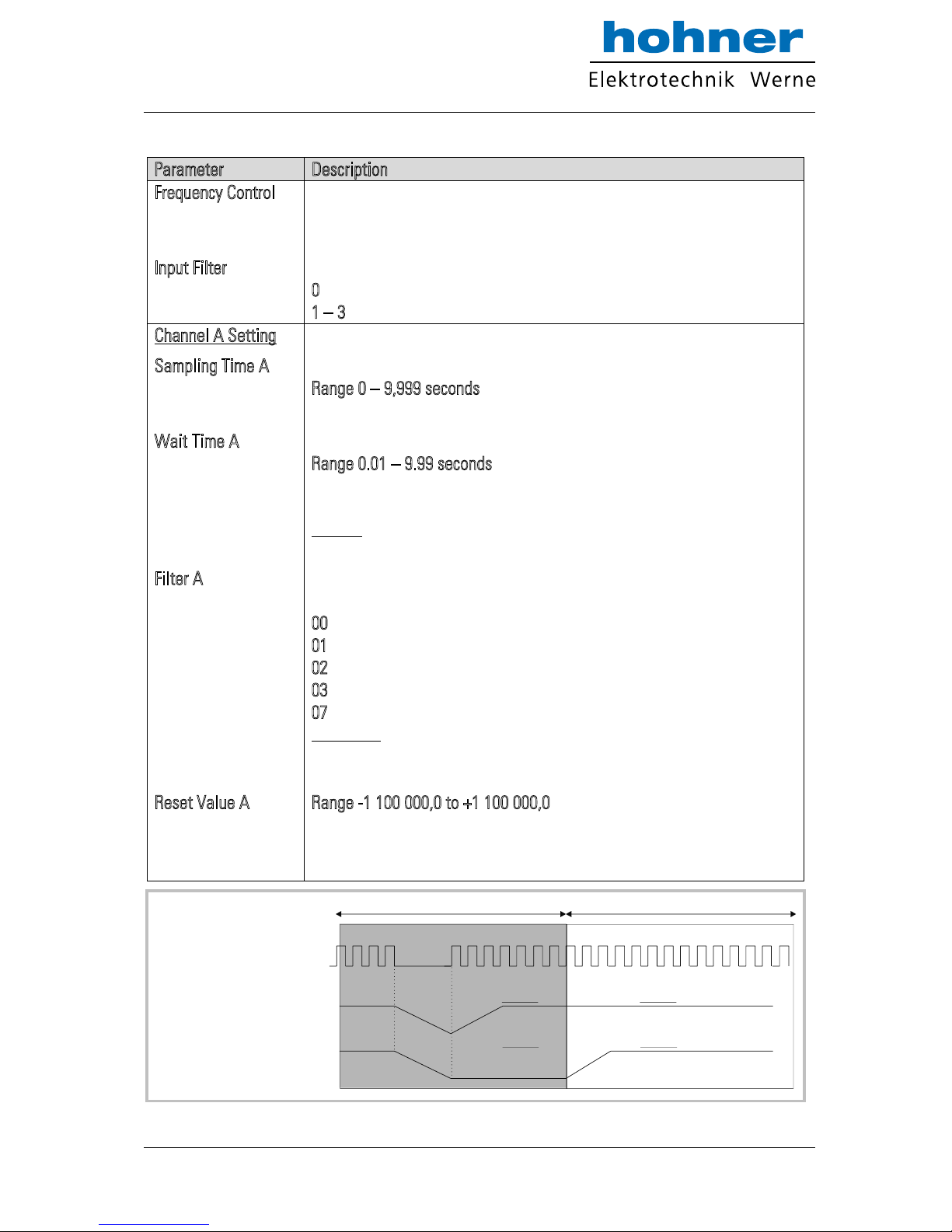
Frequency Control
Input Filter
Frequency control and response characteristics to frequency gaps for
channels A and B. This setting is taken as a 4 bit binary value.
Range 00 – 15, default setting 10 (only to be changed in special case)*
Programmable hardware filter for the impulse inputs
0
= no filtering
1
– 3 : filter low – medium - high
Channel A Setting
Sampling Time A
Wait Time A
Filter A
Reset Value A
Time base for measuring the frequency on input A
R
ange 0 – 9,999 seconds
Setting 0 provides a sampling time of 750 µs
Zero setting time for missing frequency on input A.
R
ange 0.01 – 9.99 seconds
The Analog signal goes to zero when no input impulse appears during
the Wait Time.
Example:
With setting 0,01 s all frequencies <100 Hz will produce zero output
Digital filter for smoothing the Analog output with unstable frequencies
on input A.
0
0 = Filter off (immediate response to changes of the input signal)
0
1 = Filter with time constant 1.563 ms
0
2 = Filter with time constant 3.125 ms
0
3 = Filter with time constant 6.250 ms etc.
0
7 = Filter with time constant 100 ms (slow response)
Please note:
These time constants are valid for sampling time settings of 1 ms. and higher
sampling times will correspondingly increase the time constant
Range -1 100 000,0 to +1 100 000,0
Input A will be overwritten by this simulated frequency value, if the
control input is active and the “Reset A” function has been assigned to
the control input.
*) This Parameter is
only relevant when
remarkable Sampling
Times are used. It
determines the way
how the unit responds
to gaps within one
sampling period.
Sampling Time
Input A Input B: Bit0 = 1, Bit1 = 0. : Bit2 = 1, Bit 3 = 0
Input A Input B: Bit0 = 0, Bit1 = 1. : Bit2 = 0, Bit 3 = 1
www.hohner-elektrotechnik.de 21
Page 22
Parameter
Description
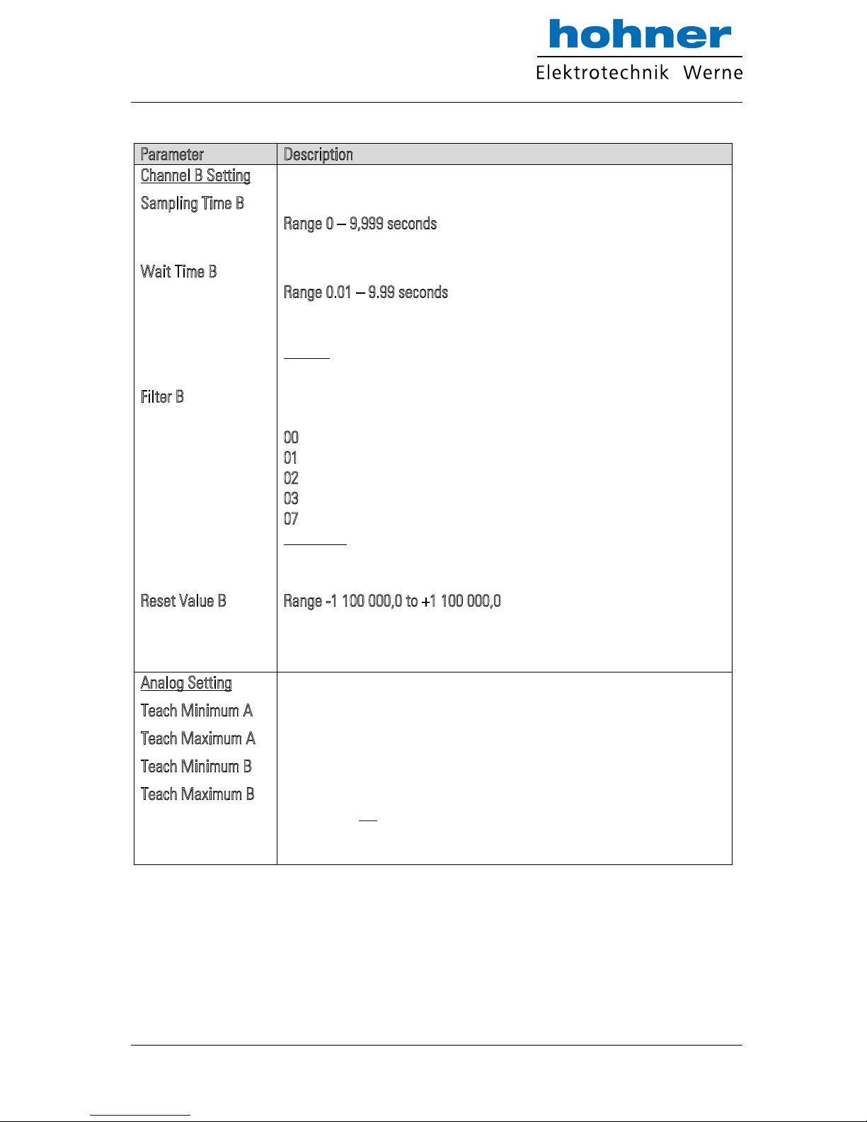
Channel B Setting
Sampling Time B
Wait Time B
Filter B
Reset Value B
Time base for measuring the frequency on input B
R
ange 0 – 9,999 seconds
Setting 0 provides a sampling time of 750 µs
Zero setting time for missing frequency on input B.
R
ange 0.01 – 9.99 seconds
The Analog signal goes to zero when no input impulse appears during
the Wait Time.
Example:
With setting 0,01 s all frequencies <100 Hz will produce zero output
Digital filter for smoothing the Analog output with unstable frequencies
on input B.
0
0 = Filter off (immediate response to changes of the input signal)
0
1 = Filter with time constant 1.563 ms
0
2 = Filter with time constant 3.125 ms
0
3 = Filter with time constant 6.250 ms etc.
0
7 = Filter with time constant 100 ms (slow response)
Please note:
These time constants are valid for sampling time settings of 1 ms. and higher
sampling times will correspondingly increase the time constant
Range -1 100 000,0 to +1 100 000,0
Input B will be overwritten by this simulated frequency value, if the
control input is active and the “Reset B” function has been assigned to
the control input.
Analog Setting
Teach Minimum A
Teach Maximum A
Teach Minimum B
Teach Maximum B
These two couples of settings define your minimum and maximum input
frequency for input A and input B (if applicable), where your Analog
output moves between 0 V and 10 V.
This is how you can enter your minimum and maximum settings:
either by operating the Teach pushbutton, like described already in
section 6.1
or by entering the frequency settings directly by keyboard to the
parameter field of your screen, without using the TEACH function
www.hohner-elektrotechnik.de 22
Page 23
Parameter
Description
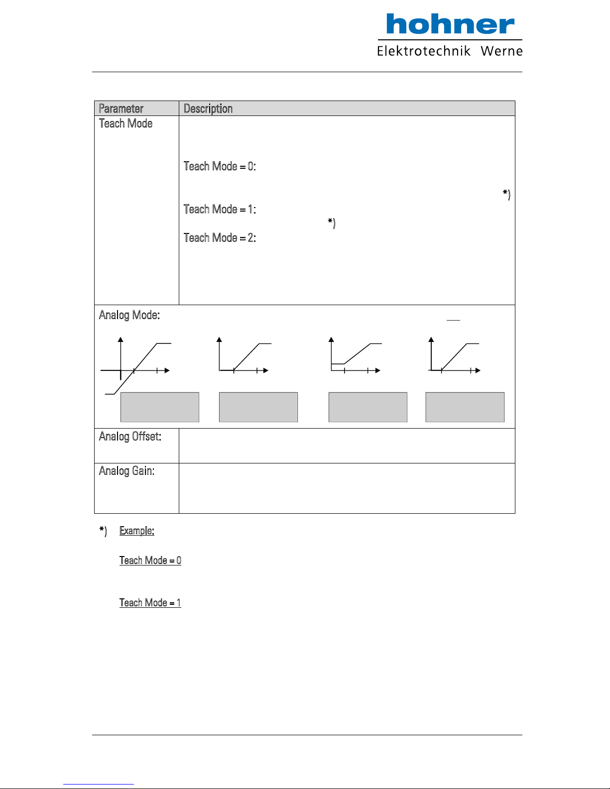
Teach Mode
This parameter is only important when your application provides a
combination of the two inputs (e.g. A + B). The setting determines how to
scale the total result of the selected A/B calculation
T
each Mode = 0: The unit will automatically calculate a new “full scale”
output, resulting from the expected maximum values
that can come up with the combined result from A and B *
)
T
each Mode = 1: The total result will use the same scaling as applied to
input channel A *
)
T
each Mode = 2: Before calculating the combination result, the channel B
frequency will be pre-scaled using the conversion
parameters „Multiplier“ and „Divisor“ , so that a direct
compare between two frequencies of different scaling
can take place.
Analog Mode: Determines which Analog output format should be used (see 5.3):
V
Encoder
Min. Max.
Output Mode = 0
-10V ... 0 ... +10V
Encoder
Min.
Max.
V
Output Mode = 1
0 ... +10V
Min.
Max.
mA
Encoder
Output Mode = 2
4 ... 20 mA
mA
Encoder
Max.
Min.
Output Mode = 3
0 ... 20 mA
Analog Offset:
Parameter to shift the zero position of the Analog output over the full range
of +/- 9999 mV resp. +/-19,998 mA (if applicable). Normal setting is 0.
Analog Gain:
Allows setting the maximum swing of the Analog output.
Setting 1000 results in a full scale signal of 10 volts or 20 mA,
setting 500 will reduce the signal to 5 volts etc.
*)
Example: Provided you have set both inputs A and B to a range of 0 … 10 kHz for a 0 … 10 volts
output, and after this you switch over to the sum mode A + B:
Teach Mode = 0 would allow to apply the full frequency range of 10 kHz to each of the inputs at the
same time, because the automatic re-scaling function has set a full range scale of 20 kHz for the
expected maximum of the sum A + B.
Teach Mode = 1 would reach the full-scale output already with a sum of A + B = 10 kHz, because only
the 10 kHz / 10 volts scaling of input A will apply
www.hohner-elektrotechnik.de 23
Page 24
Parameter
Description
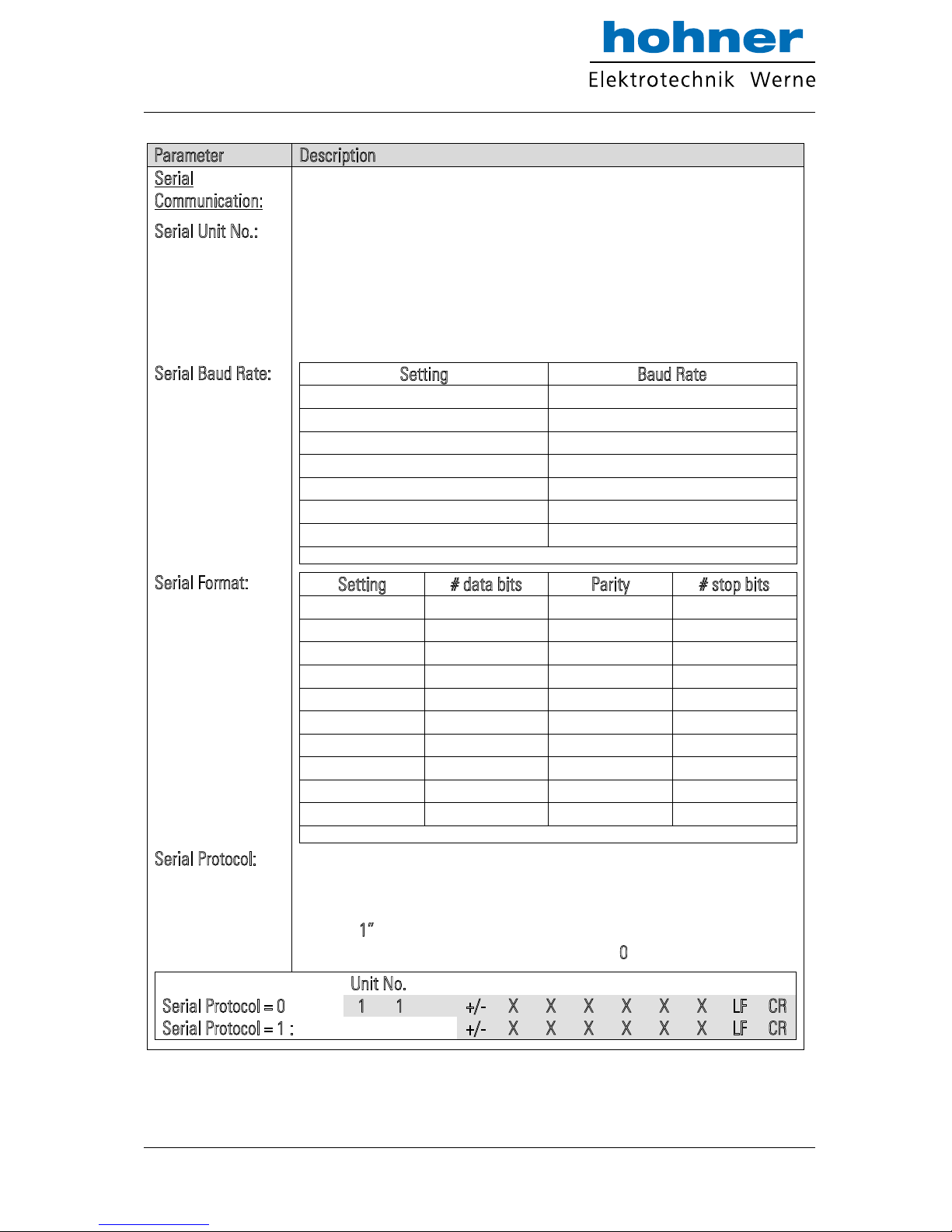
Serial
Communication:
Serial Unit No.:
Serial Baud Rate:
Serial Format:
Serial Protocol:
With RS 485 applications it is necessary to attach a specific address to
each unit, since up to 32 units can be connected to the same bus. You can
choose any address number between 11 and 99.
The address must however not contain a “0“ because these numbers are
reserved for collective addressing.
Setting
Baud Rate
0*
9600
1
4800
2
2400
3
1200
4
600
5
19200
6
38400
* = Factory setting
Setting
# data bits
Parity
# stop bits
0* 7 even
1
1 7 even
2
2 7 odd
1
3 7 odd
2
4 7 none
1
5 7 none
2
6 8 even
1
7 8 odd
1
8 8 none
1
9 8 none
2
* = Factory setting
Determines the sequence of characters sent, when you use the serial
output for cyclic data transmission under timer control
(xxxxxxx is the measuring value transmitted).
Setting “1
” will suppress transmission of the unit number, therefore the
transmission cycle is shorter than with setting “0
”
Unit No.
Serial Protocol = 0 :
1 1
+/- X X X X X X
LF
CR
Serial Protocol = 1 :
+/- X X X X X X
LF
CR
www.hohner-elektrotechnik.de 24
Page 25
Parameter
Description
Serial Timer:
Serial Value:
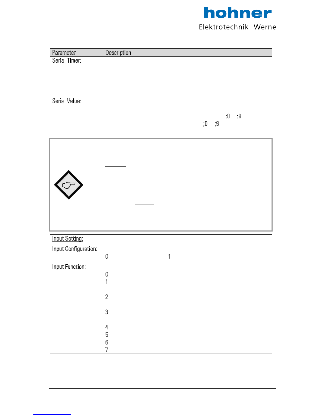
This register determines the cycle time in seconds for cyclic
transmission when the Printer Mode is switched on.
Range 0.001 to 99.999 seconds.
With setting “0” all cyclic transmission is switched off and the unit will
only send data upon request (PC mode *)
Sets the code of the register of which the content should be sent with
cyclic transmission.
Setting range 00 – 09 (corresponds to register codes :
0 to :9)
and 10 - 19 (corresponds to register codes ;
0 to ;9)
For clarification of register codes see sections 10 and 11.
*) The serial port of the unit can operate in either “PC-Mode“ or in
“Printer Mode“.
With “PC-Mode“, the unit receives a request string and responds with a
corresponding data string. For details of the protocol see separate description
“SERPRO“.
With “Printer Mode“ the unit sends data without any request and under Timer
control as described subsequently.
As soon as the unit receives a character, it automatically switches over to PC
Mode and operates according to protocol. When for a period of 20 s no
character has been received, the unit switches automatically back to
“Printer Mode“ and starts cyclic data transmission again.
Input Setting:
Input Configuration:
Input Function:
Sets the switching characteristics of the „Control“ input (terminal 10):
0
= function „active HIGH“, 1 = function „active LOW“
Selects the function of the “Control” input (terminal 10):
0
= no control function
1
= Replaces the frequency applied to input A by a fixed frequency
value as set under parameter „Reset Value A“
2
= Replaces the frequency applied to input B by a fixed frequency
value as set under parameter „Reset Value B“
3
= Replaces the result of the combination A / B by a fixed value as
set under parameter „Reset Value A/B“
4
= Freezes the actual frequency value of input A
5
= Freezes the actual frequency value of input B
6
Freezes both frequencies A and B
7 = Starts a serial transmission of the defined register value
www.hohner-elektrotechnik.de 25
Page 26
Parameter
Description
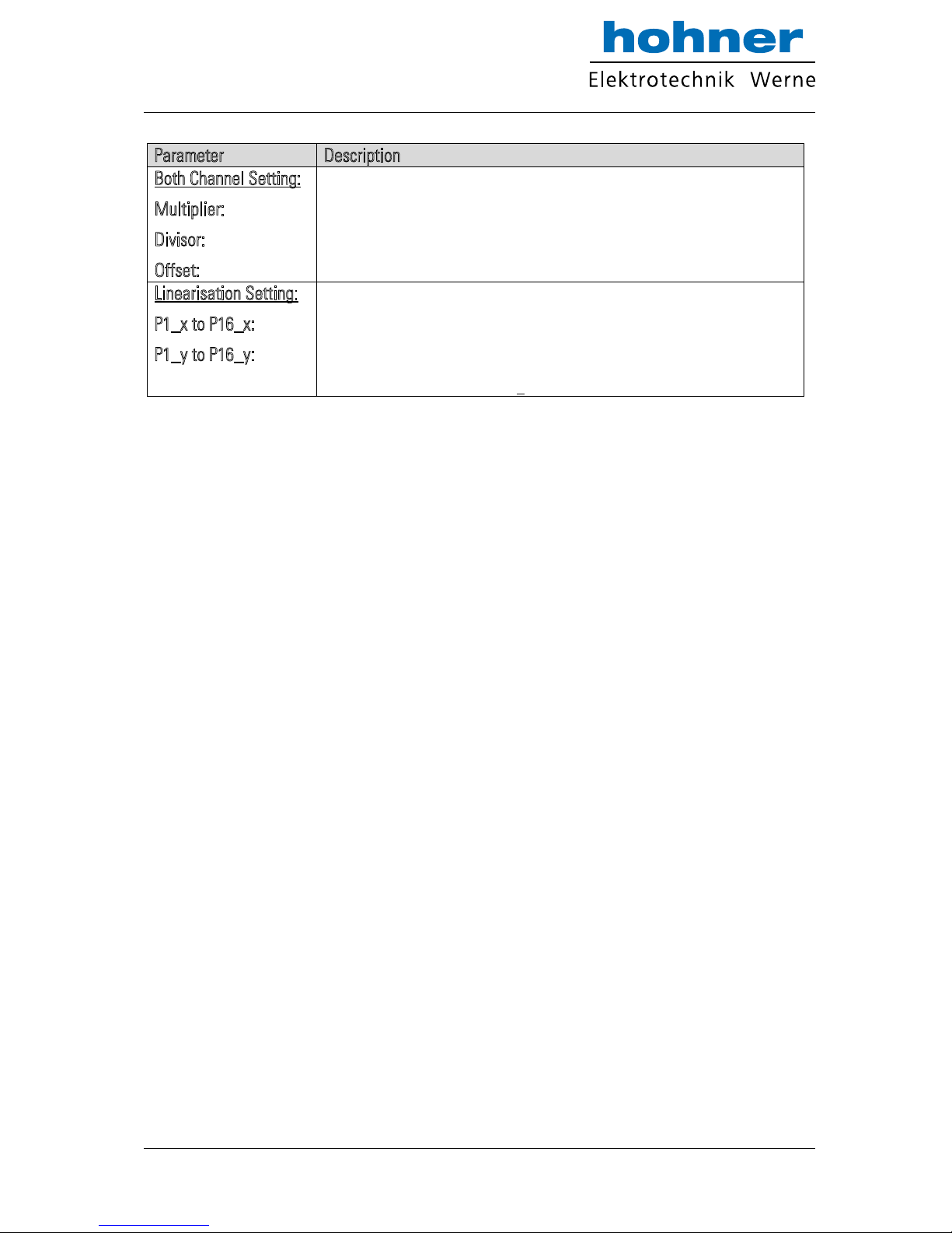
Both Channel Setting:
Multiplier:
Divisor:
Offset:
These settings provide a final scaling of the calculation result from
the combined operation modes A / B
Linearisation Setting:
P1_x to P16_x:
P1_y to P16_y:
Interpolation points for linearization (initial values)
Interpolation points for linearization (substitute values)
(For clarification see section 9)
www.hohner-elektrotechnik.de 26
Page 27
9. Free Programmable Linearization
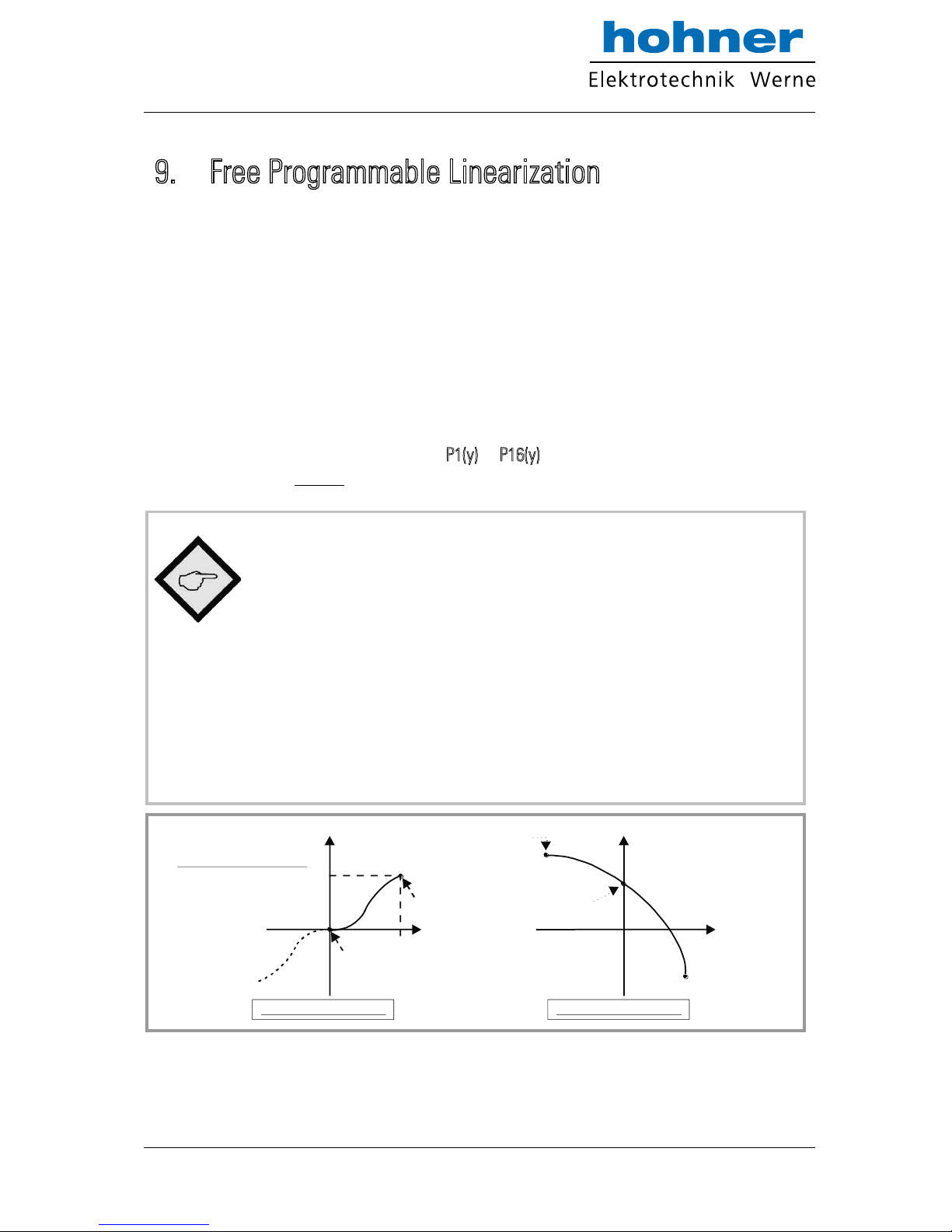
This programmable feature allows the user to convert a linear input signal to a non- linear
Analog output. There are 16 programmable x/y coordinates available, which can be set in any
desired distance over the full conversion range. Between two coordinates, the unit uses linear
interpolation. Therefore it is advisable to use more coordinates in a range with strong curves
and only a few coordinates where the curvature is less.
To specify your desired linearization curve, you must first set the „Linearisation Mode“ register
to either 1 or 2.
Use registers P1(x) to P16(x) to specify the coordinates on the x-axis. These are the Analog
output values that the unit normally would generate according to the actual input frequency.
These settings must be in % of full scale.
Now enter the attached values to registers P1(y) to P16(y). These are the values that the Analog
output will generate instead of the x- values, i.e. P2(y) will substitute P2(x) etc.
x-registers must use continuously increasing settings, i.e. P1(x) must
have the lowest and P16(x) must have the highest setting
All entries use a percental format of xx.xxx% full scale.
Setting 000.000% means zero output and
setting 100.000% means full scale output.
With Linearisation Mode set to 1, it is a must to set P1(x) to 0% and
P16(x) to 100%. Linearisation is defined in the positive range only and
the negative range will be a mirror image of the positive range with
reference to zero.
With Linearisation Mode set to 2, it is a must to set P1(x) to –100%
and P16(x) to +100%. This enables the user to set curves which are
not symmetric to the zero position.
x
y
P1(x)= 0%
P1(y)=10%
Linearisation Mode = 1
x
y
Linearisation Mode = 2
P1(x)= -100%
P1(y)= 95%
P8(x)= 0%
P8(y)= 80%
P16(x)=+100%
P16(y)= -60%
*)
P16(x)=100%
P16(y)= 80%
*) Output mode = 0
www.hohner-elektrotechnik.de 27
Page 28
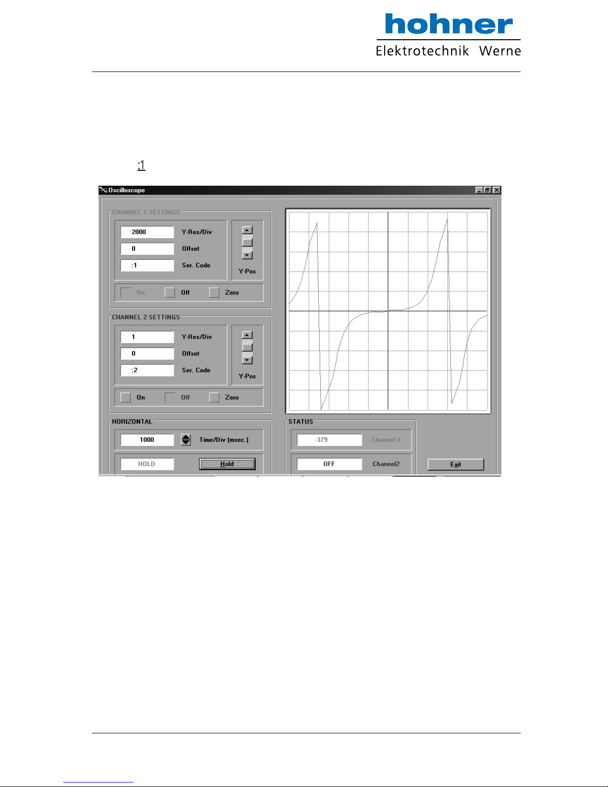
You can visualize your curve on the PC screen or by means of an external oscilloscope.
For this, select TOOLS, then TEST and there „Analog Voltage Function“. The unit will now
simulate a repeating frequency course over the full range and generate the Analog signal
accordingly. When you use the Scope function of the operator software, you must set the serial
code to „:
1” to record the Analog output.
www.hohner-elektrotechnik.de 28
Page 29
10. Monitor Functions
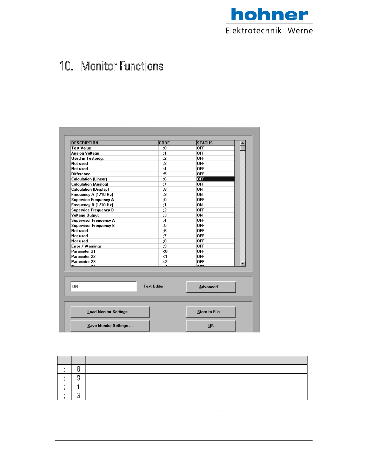
The monitor function of the OS3.2 PC software allows to display some important data on the PC
screen with a continuous refresh cycle.
Select „Monitor“ from the „Tools“ menu to open the basic view of the monitor window. Click to
“Define” to open the definition window. You will find a list with all accessible parameters and
actual values, where however the texts may be unfounded.
With FU252, only the following register codes make sense:
C1
C2
Description
: 8 Actual conversion result in % of full-scale, format xxx.xxx % *)
: 9 Actual frequency on input A in Hz, resolution 0.1 Hz, format xxx xxx.x Hz
; 1 Actual frequency on input B in Hz, resolution 0.1 Hz, format xxx xxx.x Hz
; 3 Actual output voltage of the Analog output, scaling 0 … 10 000 millivolts
*) In accordance to the applied conversion scaling see chapter 8.
www.hohner-elektrotechnik.de 29
Page 30
Click to the Status field, next to the desired register code (where you read ON or OFF). Now you
can toggle this position between ON and OFF by touching any key.
Set all of the register codes to ON which you afterwards would like to trace on the monitor.
Switch all unused register codes to OFF.
To change the text shown with the register code, click to the corresponding text field. The same
text will now appear in the “Text Editor” window below the parameter window. Rename the
text according to your desire and press ENTER to store the new text in the corresponding
monitor line.
When all desired codes have been set to ON and the texts have been renamed according to
need, click OK. Where, besides the display data on the screen, you also like to record all data to
a file on your hard disc, click first to „Store to File“ and set the corresponding check box.
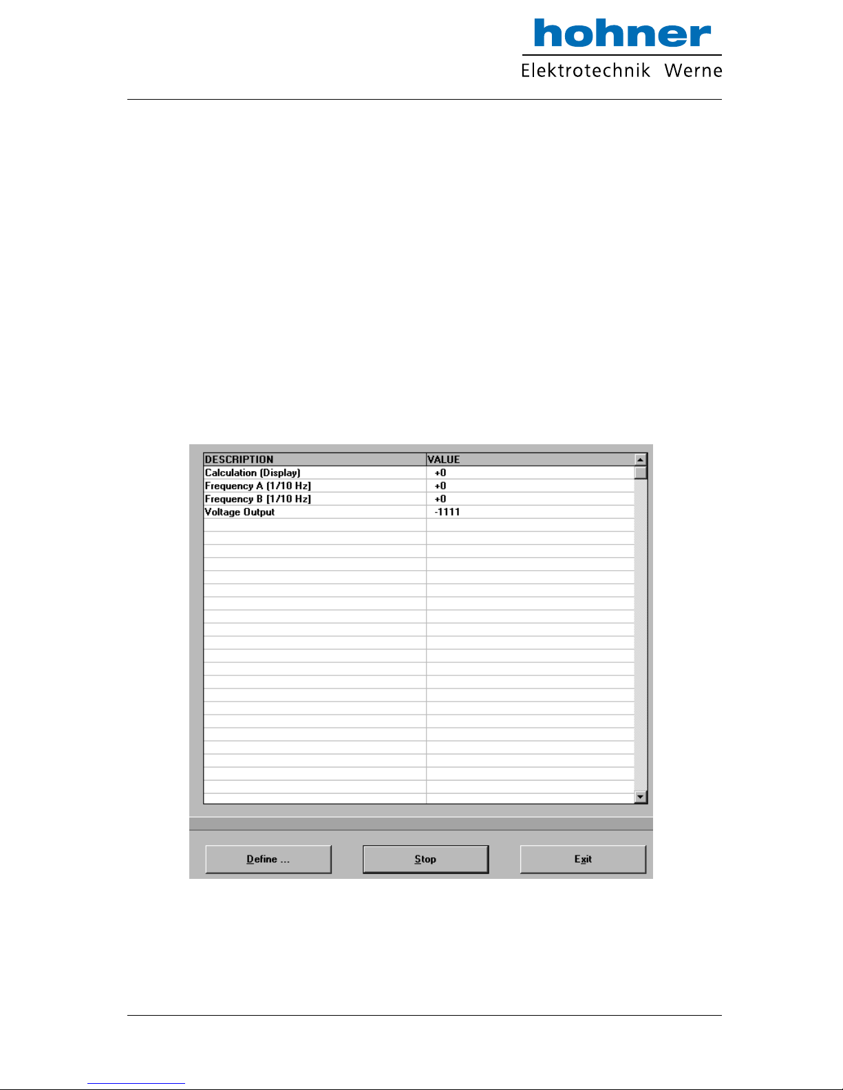
After starting the monitor, you will see the following window where all values are updated
continuously:
www.hohner-elektrotechnik.de 30
Page 31
11. Data Readout via Serial Interface
All register codes from section 10 are also available for serial readout by PC or PLC. For
communication the FU252 converter uses the Drivecom Protocol according to ISO 1745. All
protocol details can be found in our manual S
ERPRO_2a.doc which is available for download
from our homepage
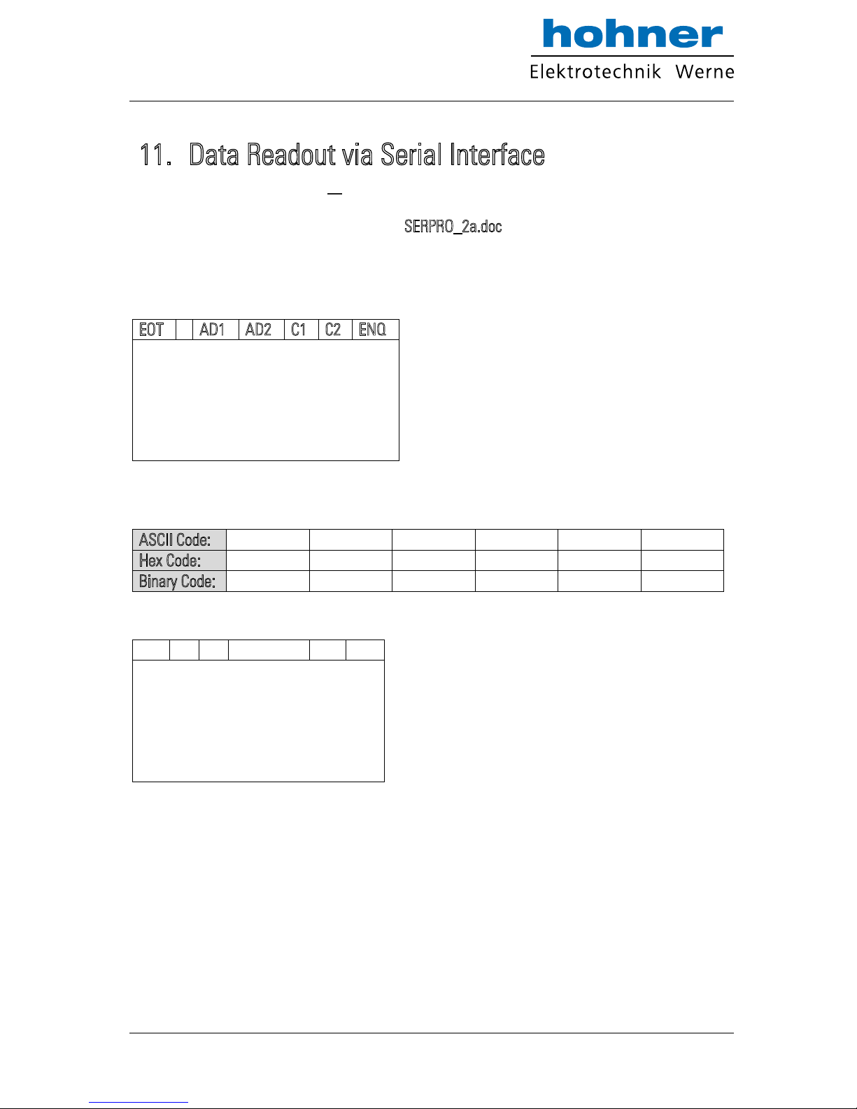
To request for a data transmission you must send the following request string to the converter:
EOT
AD1
AD2
C1
C2
ENQ
EOT = control character (Hex 04)
AD1 = unit address, High Byte
AD2 = unit address, Low Byte
C1 = register code, High Byte
C2 = register code, Low Byte
ENQ = control character (Hex 05)
The following example shows the request string for readout of the actual frequency of input A
(code :9) from a unit with unit address 11:
ASCII Code:
EOT 1 1 : 9
ENQ
Hex Code:
04
31
31
3A
39
05
Binary Code:
0000 0100
0011 0001
0011 0001
0011 1010
0011 1001
0000 0101
After a correct request, the unit will respond:
STX
C1
C2
x x x x x x x
ETX
BCC
STX = control character (Hex 02)
C1 = register code, High Byte
C2 = register code, Low Byte
xxxxx = readout data
ETX = control character (Hex 03)
BCC = block check character
For all further details see SERPRO_2a.doc.
www.hohner-elektrotechnik.de 31
Page 32
12. Dimensions
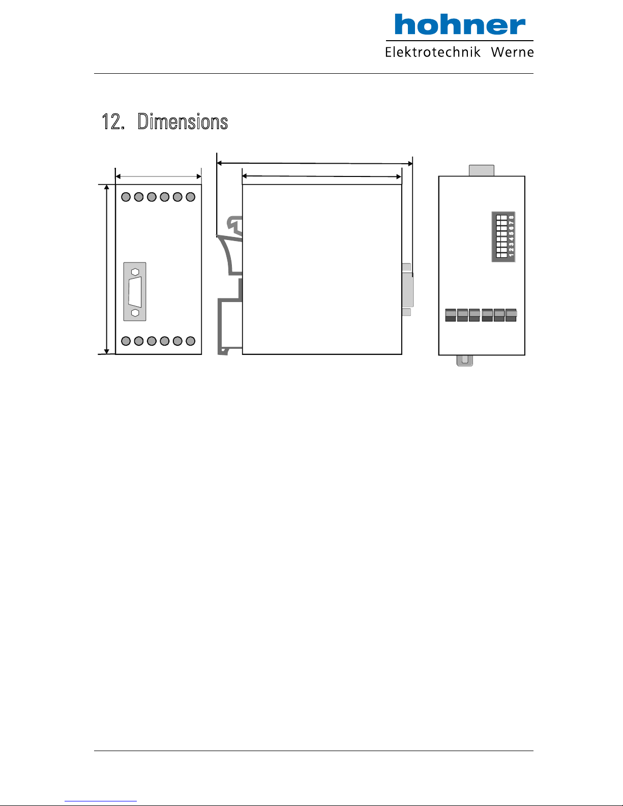
74 mm (2.913’’)
91mm (3.583’’)
40 mm (1.575’’)
79 mm (3.110’’)
Front view
Side view
Top view
www.hohner-elektrotechnik.de 32
Page 33
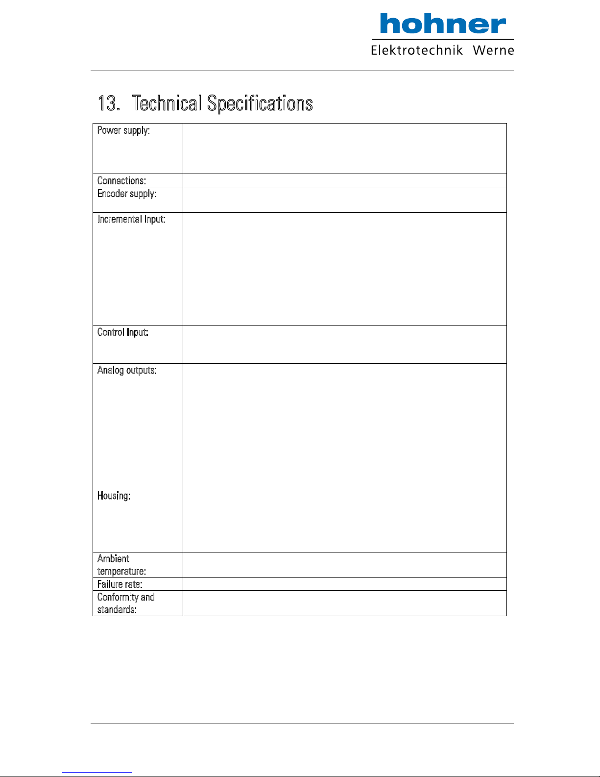
13. Technical Specifications
Power supply:
Input voltage:
Protection circuit:
Ripple:
Consumption:
18 … 30 VDC
reverse polarity protection
≤ 10 % at 24 VDC
approx. 75 mA at 24 V (unloaded encoder supply)
Connections:
Connector type:
screw terminals, 1.5 mm² / AWG 16
Encoder supply:
Output voltage:
Output current:
+ 5.5 VDC / +/- 5 %
max. 250 mA
Incremental Input:
Signal levels:
HTL characteristic:
HTL internal resistance:
Channels:
Frequency:
Measurement accuracy:
RS422: Differential voltage > 1 V
TTL: LOW: 0 … 0.5 V / HIGH: 2.5 … 5.3 V
HTL: LOW: 0 … 3 V / HIGH: 10 … 30 V
NPN / PNP
Ri ≈ 4.75 kOhm
A, /A, B, /B
max. 1 MHz at RS422 and TTL symmetrical
max. 200 kHz at HTL and TTL asymmetrical
0.02 % +/- 1 digit
Control Input:
Application:
Signal levels:
Pulse time:
proximity switches or control commands
LOW < 3 V / HIGH >10 V
min. 5 ms
Analog outputs:
Voltage:
Current:
Resolution:
Accuracy:
Resolution per bit:
Reaction time
(standard operation):
Reset time (in case of
a sudden interruption):
- /+ 10 V (external load max. 5 kOhm)
0/4 … 20 mA (burden max. 270 Ohm)
14 Bit
0.1%
1.25 mV / 2,5 µA
depends on sampling time and frequency;
approx. 1 ms (fin > 2 kHz); 1/f in (fin < 1 kHz)
5 ms (without average), 700 ms (max. average)
Housing:
Material:
Mounting:
Dimensions (w x h x d):
Protection class:
Weight:
plastic
35 mm top hat rail (according to EN 60715)
40 x 79 x 91 mm / 1.5748 x 3.1102 x 3.5827 inch
IP20
approx. 190 g
Ambient
temperature:
Operation:
Storage:
0 °C … +45 °C / +32 … +113 °F (not condensing)
-25 °C … +70 °C / -13 … +158 °F (not condensing)
Failure rate:
MTBF in years:
75.2 a (long-term usage at 60 °C / 140 °F )
Conformity and
standards:
EMC 2004/108/EC:
Guideline 2011/65/EU:
EN 61000-6-2, EN 61000-6-3, EN 61000-6-4
RoHs-conform
www.hohner-elektrotechnik.de 33
Page 34
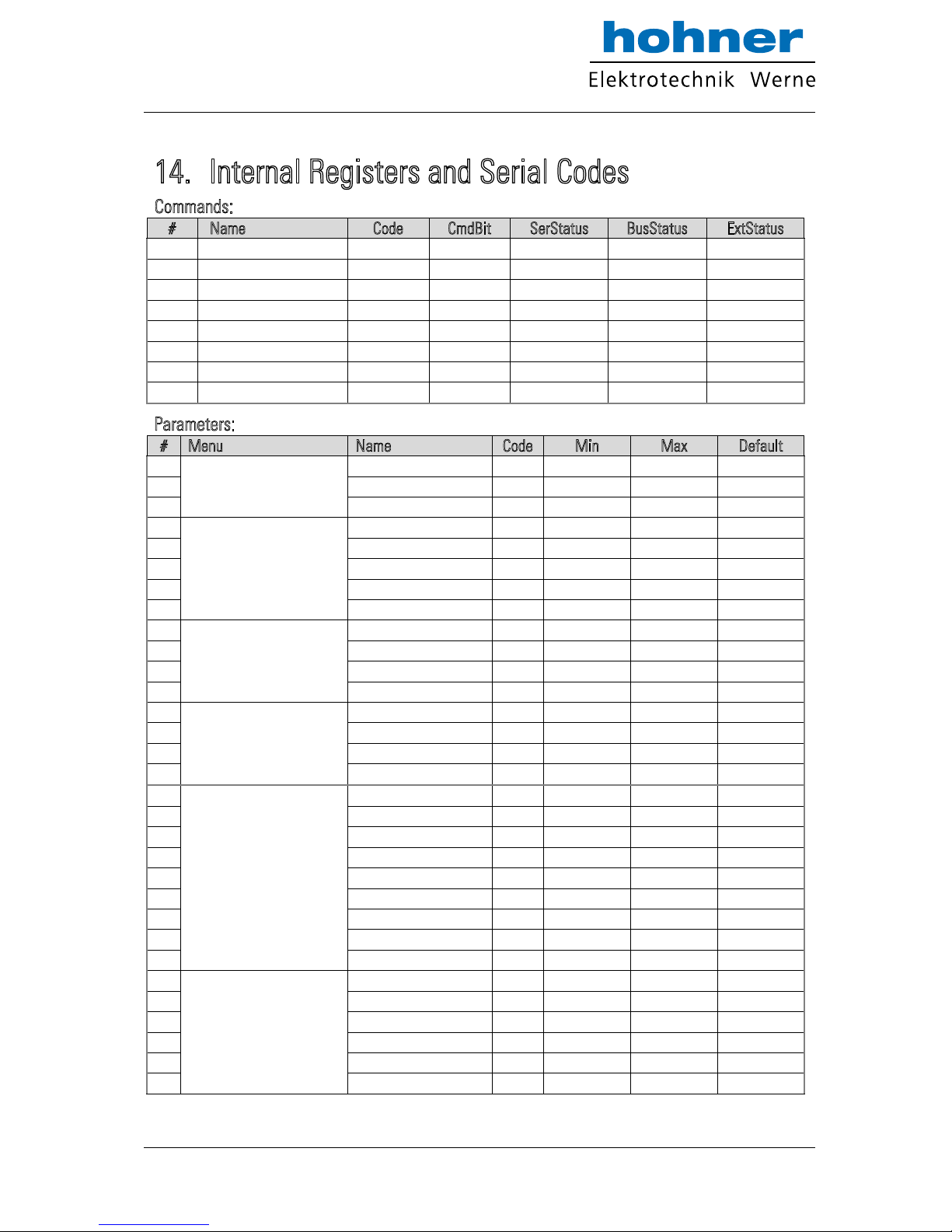
14. Internal Registers and Serial Codes
Commands:
#
Name
Code
CmdBit
SerStatus
BusStatus
ExtStatus
7
FreezeBoth
61
0040
Yes
No
Yes
8
FreezeB
62
0020
Yes
No
Yes
9
FreezeA
63
0010
Yes
No
Yes
10
ResetBoth
64
0008
Yes
No
Yes
11
ResetB
65
0004
Yes
No
Yes
12
ResetA
66
0002
Yes
No
Yes
13
ActivateData
67
1000
Yes
No
No
14
StoreEEProm
68
0001
Yes
No
No
Parameters:
#
Menu
Name
Code
Min
Max
Default
0
Register-Setting(:8)
Multiplier
00
-1000000
1000000
10000
1 Divisor
01 0 1000000
0
2 Offset
02
-1000000
1000000
0
3
General-Setting
Direction
46
0 1 0
4 FilterAB
11 0 12
0
5 LinearisationMode
08
0 2 0
6 FrequencyControl
D2 0 15
10
7 InputFilter
D3
0 3 0
8
Channel-A-Setting
SamplingTimeA
33 0 9999
0
9 WaitTimeA
09 1 999
100
10 FilterA
D6
0 7 0
11 ResetValueA
D7
-10000000
10000000
0
12
Channel-B-Setting
SamplingTimeB
34 0 9999
0
13 WaitTimeB
10 1 999
100
14 FilterB
D8
0 7 0
15 ResetValueB
D9
-10000000
10000000
0
16
Analog-Setting
TeachMinA
03
-10000000
10000000
0
17 TeachMaxA
04
-10000000
10000000
10000
18 TeachMinB
05
-10000000
10000000
0
19 TeachMaxB
06
-10000000
10000000
10000
20 TeachMode
12
0 2 0
21 AnalogMode
07
0 3 1
22 AnalogOffset
47
-9999
9999
0
23 AnalogGain
48 0 10000
1000
24 Reserved
E0 0 9999
1000
25
Serial-Communication
SerialUnitNo.
90 0 99
11
26 SerialBaudRate
91
0 6 0
27 SerialFormat
92
0 9 0
28 SerialProtocol
30
0 1 0
29 SerialTimer
31 0 99999
0
30 SerialValue
32 0 19
0
www.hohner-elektrotechnik.de 34
Page 35
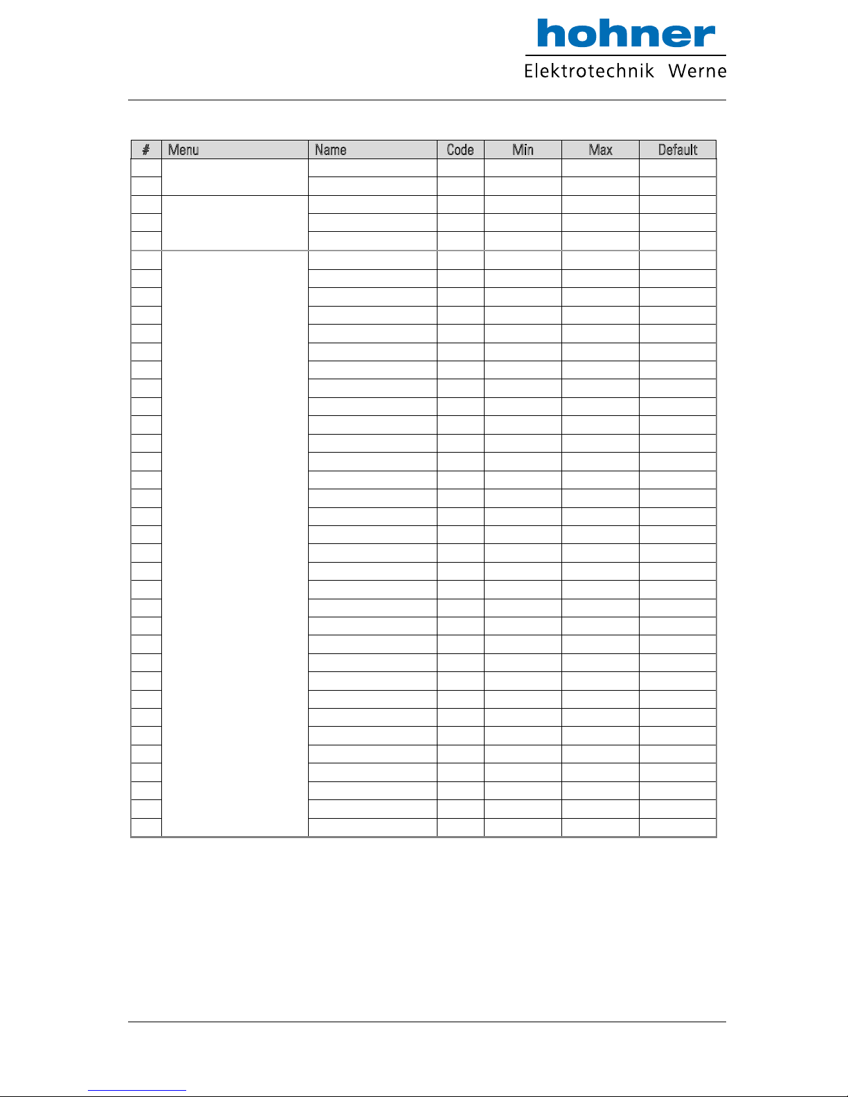
#
Menu
Name
Code
Min
Max
Default
31
Input-Setting
InputConfiguration
E2
0 1 0
32 InputFunction
E3
0 7 0
33
Both-Channel-Setting
Multiplier
13
-1000000
1000000
10000
34 Divisor
14 1 1000000
10000
35 Offset
15
-1000000
1000000
0
36
Linearisation-Setting
P1(x)
A0
-100000
100000
100000
37 P1(y)
A1
-100000
100000
100000
38 P2(x)
A2
-100000
100000
100000
39 P2(y)
A3
-100000
100000
100000
40 P3(x)
A4
-100000
100000
100000
41 P3(y)
A5
-100000
100000
100000
42 P4(x)
A6
-100000
100000
100000
43 P4(y)
A7
-100000
100000
100000
44 P5(x)
A8
-100000
100000
100000
45 P5(y)
A9
-100000
100000
100000
46 P6(x)
B0
-100000
100000
100000
47 P6(y)
B1
-100000
100000
100000
48 P7(x)
B2
-100000
100000
100000
49 P7(y)
B3
-100000
100000
100000
50 P8(x)
B4
-100000
100000
100000
51 P8(y)
B5
-100000
100000
100000
52 P9(x)
B6
-100000
100000
100000
53 P9(y)
B7
-100000
100000
100000
54 P10(x)
B8
-100000
100000
100000
55 P10(y)
B9
-100000
100000
100000
56 P11(x)
C0
-100000
100000
100000
57 P11(y)
C1
-100000
100000
100000
58 P12(x)
C2
-100000
100000
100000
59 P12(y)
C3
-100000
100000
100000
60 P13(x)
C4
-100000
100000
100000
61 P13(y)
C5
-100000
100000
100000
62 P14(x)
C6
-100000
100000
100000
63 P14(y)
C7
-100000
100000
100000
64 P15(x)
C8
-100000
100000
100000
65 P15(y)
C9
-100000
100000
100000
66 P16(x)
D0
-100000
100000
100000
67 P16(y)
D1
-100000
100000
100000
www.hohner-elektrotechnik.de 35
Page 36
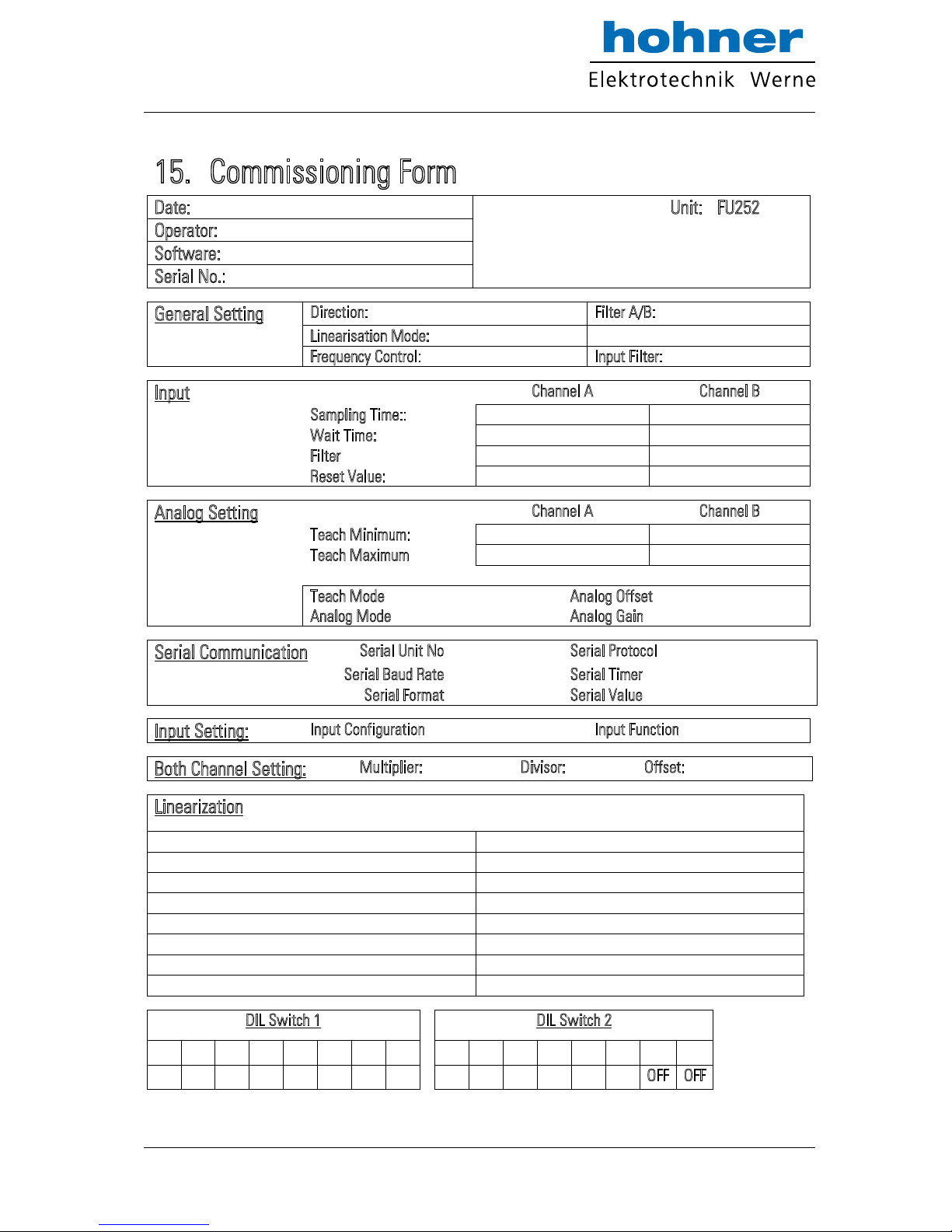
15. Commissioning Form
Date:
Unit:
FU252
Operator:
Software:
Serial No.:
General Setting
Direction:
Filter A/B:
Linearisation Mode:
Frequency Control:
Input Filter:
Input
Channel A
Channel B
Sampling Time::
-
Wait Time:
-
Filter
-
Reset Value:
-
Analog Setting
Channel A
Channel B
Teach Minimum:
Teach Maximum
Teach Mode
Analog Offset
Analog Mode
Analog Gain
Serial Communication
Serial Unit No
Serial Protocol
Serial Baud Rate
Serial Timer
Serial Format
Serial Value
Input Setting:
Input Configuration
Input Function
0
Both Channel Setting:
Multiplier:
Divisor:
Offset:
Linearization
P01_X:
P01_Y:
P09_X:
P09_Y:
P02_X:
P02_Y:
P10_X:
P10_Y:
P03_X:
P03_Y:
P11_X:
P11_Y:
P04_X:
P04_Y:
P12_X:
P12_Y:
P05_X:
P05_Y:
P13_X:
P13_Y:
P06_X:
P06_Y:
P14_X:
P14_Y:
P07_X:
P07_Y:
P15_X:
P15_Y:
P08_X:
P08_Y:
P16_X:
P16_Y:
DIL Switch 1
DIL Switch 2
-1-
-2-
-3-
-4-
-5-
-6-
-7-
-8- -1-
-2-
-3-
-4-
-5-
-6-
-7-
-8-
OFF
OFF
www.hohner-elektrotechnik.de 36
 Loading...