

Page 1
Operating Instructions Page 1
Spare parts list E1
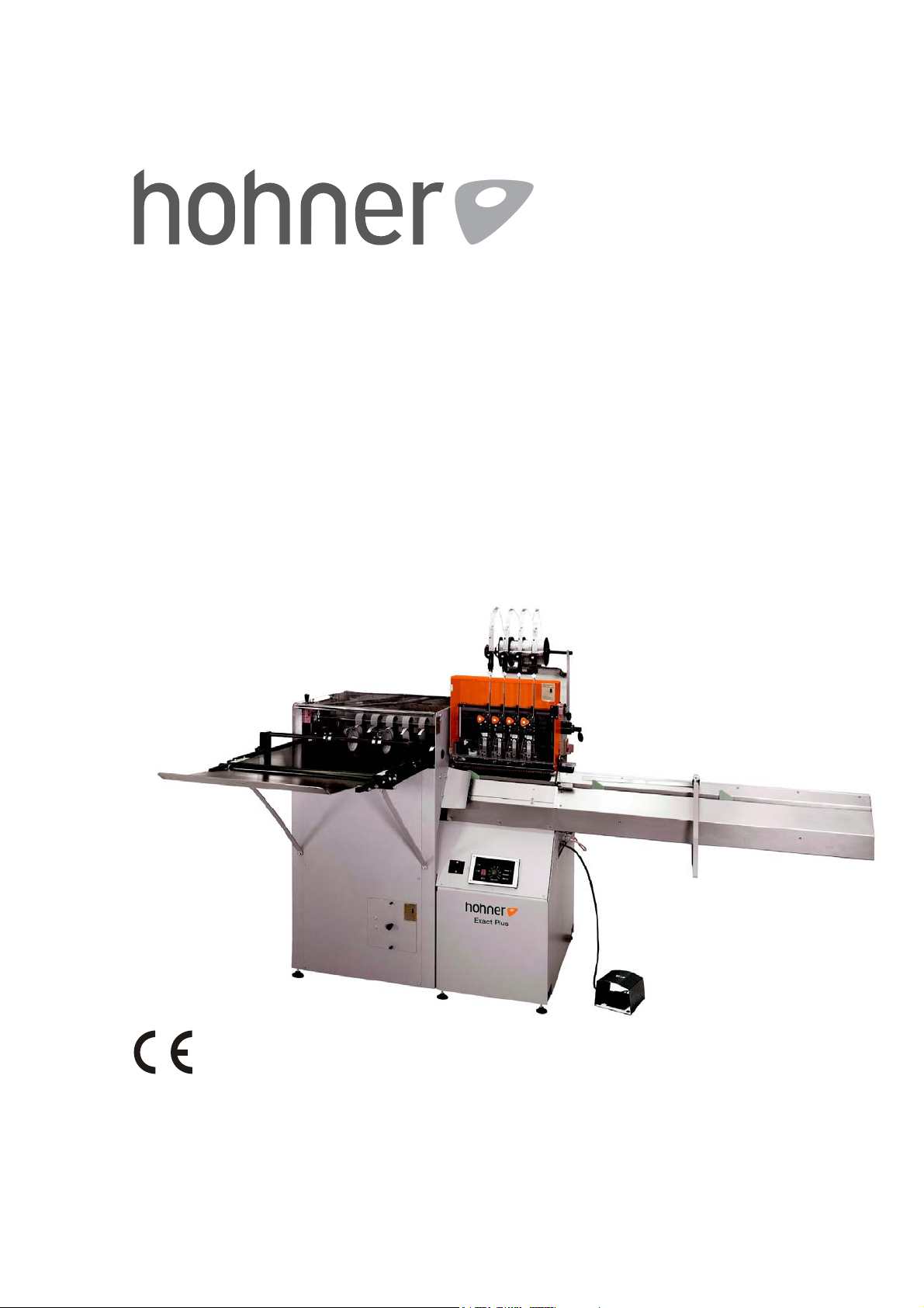
EXACT-PLUS
Semiautomatic
booklet wire
stitching machine
Hohner Maschinenbau GmbH
Gänsäcker 19, D-78532 Tuttlingen, Telefon +49 (0) 74 62 / 94 68-0, Telefax +49 (0) 74 62 / 94 68-20
Page 2

2 EXACT-PLUS 10/2010 Hohner Maschinenbau GmbH
Page 3

Customer Details
Inventory no.: ...........................
Location ...........................
Manufacturer's Address
Company name: hohner
Maschinenbau GmbH
Street: Gänsäcker 19
Town: D-78532 Tuttlingen
Telephone: +49 (0) 74 62 / 94 68-0
Fax: +49 (0) 74 62 / 94 68-20
Email: [email protected]
Internet home page: www.hohner-postpress.com
Obtaining Spare Parts / Customer Service
Telephone: +49 (0) 74 62 / 94 68-0
Fax: +49 (0) 74 62 / 94 68-20
Operating Manual
Document: Translation of the german original Operating
Instructions
Document number: EXACT-PLUS, Volume 1/2
Version: 10/2010
Spare Parts Lists
Document number: EXACT-PLUS, Volume 2/2
Hohner Maschinenbau GmbH EXACT-PLUS 10/2010 3
Page 4

Table of Contents
Table of Contents
1 Basic safety precautions.................................................................................. 5
1.1 Purpose of this document .............................................................................................. 5
1.2 The operator .................................................................................................................. 5
1.3 Safety symbols and the displays in use......................................................................... 5
1.4 Duty and liability............................................................................................................. 6
1.5 Correct use of the machine............................................................................................ 6
1.6 User requirements ......................................................................................................... 6
1.7 Safety and protective systems....................................................................................... 6
1.8 Informal safety measures .............................................................................................. 6
1.9 Personnel training.......................................................................................................... 6
1.10 Parts of the machine that are particularly dangerous .................................................... 7
1.11 Servicing and repair work, elimination of faults ............................................................. 7
1.12 Structural modifications to the machine......................................................................... 7
1.13 Cleaning the machine and the removal of waste products ............................................ 7
1.14 Noise levels produced by the machine .......................................................................... 7
2 Description of the stitching machine EXACT-PLUS ........................................ 8
2.1 Safety-related components............................................................................................ 9
2.1.1 Position of the cut-out switch / emergency switch ..................................................... 9
2.1.2 Stitching aggregate.................................................................................................... 9
2.1.3 Delivery...................................................................................................................... 9
2.1.4 Staggered stitch......................................................................................................... 9
2.1.5 Main switch and emergency switch ........................................................................... 9
2.2 Electrical connections ................................................................................................. 11
2.3 Motor protective relay .................................................................................................. 11
2.4 Block mode for drive motor sliding connecting rods .................................................... 11
2.5 Dimensions .................................................................................................................. 13
2.6 Conformity ................................................................................................................... 13
2.7 Marking and type plate ................................................................................................ 13
2.8 Technical data ............................................................................................................. 13
2.9 Accessories ................................................................................................................. 15
2.9.1 Equipment ............................................................................................................... 15
2.9.2 Tools........................................................................................................................ 15
3 Installation and commissioning of the machine ............................................. 16
3.1 Installation.................................................................................................................... 17
3.2 Mounting - stitching head............................................................................................. 17
3.3 Mounting - clincher box................................................................................................ 19
3.4 Fine adjustment - clincher box..................................................................................... 21
3.5 Pressure adjustment - clincher back press.................................................................. 21
3.6 Mounting and adjustment - guiding brushes / guiding angle ....................................... 23
3.7 Mounting - centering device and guiding cam ............................................................. 23
3.8 Adjustment - stitching thickness at the stitching aggregate ......................................... 25
3.9 Adjustment - stitching thickness on the delivery .......................................................... 25
3.10 Adjustment - paper stop in the delivery ....................................................................... 27
3.11 Adjustment - guiding rollers on the delivery table ........................................................ 29
3.12 Adjust by hand - stitching head actuation .................................................................... 31
3.13 Adjustment - "staggered stitch".................................................................................... 33
3.14 Carbon brushes and switch-off brushes ...................................................................... 35
4 Flow diagrams ............................................................................................... 36
4 EXACT-PLUS 10/2010 Hohner Maschinenbau GmbH
Page 5
Basic safety precautions
1 Basic safety precautions
1.1 Purpose of this document
This document is to inform the operator of the Wire Stitching Machine EXACT-PLUS about the
following matters:
• the safety symbols and signs
• the installation and commissioning
• the adjustment and operation
Familiarity with this Operating Manual is a prerequisite for the safe and correct running of the
machine. It must be read carefully by the operator before the machine is commissioned.
Keep the manual safely in a place where it is readily available and which is close to hand for persons working on the machine.
1.2 The operator
The Wire Stitching Machine EXACT-PLUS must only be operated by trained personnel.
Training will be undertaken by the manufacturer or by persons who have been authorised by the
manufacturer to undertake such training.
1.3 Safety symbols and the displays in use
This symbol displays immediate danger to the life or health of persons
in the immediate vicinity of the machine.
Non-observance of the warnings indicated can have immediate, grave con-
sequences and can cause extensive damage to health or may even lead to
death.
This symbol displays possible danger to the life or health of persons
in the immediate vicinity of the machine.
Non-observance of the warnings indicated can have grave consequences,
and can cause extensive damage to health, or may even lead to death.
This symbol displays the existence of a potentially dangerous
situation.
Non-observance of the warnings indicated can lead to minor injuries to persons.
This symbol displays the existence of the risk of damage to
equipment.
Non-observance of the warnings indicated can lead to slight damage to
equipment.
This symbol indicates the availability of tips on how to use the
machine or particularly useful information.
TIP
These tips will help you to use all of the functions of the machine to best
advantage.
- This sign requires you to take action.
• This sign serves as a symbol for listing items.
Hohner Maschinenbau GmbH EXACT-PLUS 10/2010 5
Page 6

Basic safety precautions
1.4 Duty and liability
The Wire Stitching Machine EXACT-PLUS has been built according to state-of-the-art technology
under the observance of all the recognised safety regulations. It is, nevertheless, still possible when
using this machine to cause danger to life and limb of the user or a third party or to cause damage
to the machine or other property.
The machine should only be used,
• for the purpose for which it was designed
• when it is in a perfect technical condition
Faults that could reduce the levels of safety in using the machine must be removed immediately.
Warranties and liability on the part of the manufacturer are fundamentally covered by the regulations laid down in our ”General sales and delivery conditions”.
1.5 Correct use of the machine
The Wire Stitching Machine EXACT-PLUS is designed exclusively stitching of brochures and
leaflets or similar items. Any use of the machine contrary to that described above is forbidden since
incorrect use of the machine can present a danger.
1.6 User requirements
The user of the machine is required to provide the required personal safety equipment. All existing
safety systems should be checked regularly.
1.7 Safety and protective systems
All safety and protective systems must be attached to the machine and should be in full working
order before every start-up of the machine.
Safety and protective systems may only be removed:
• when the machine is stationary and
• after it has been secured against being started up again.
1.8 Informal safety measures
The Operating Manual should be stored in such a way as to be permanently to hand at the
machine. There are also generally valid local regulations concerning accident prevention and environmental protection measures that should be made available and observed, in addition to those
described in the Operating Instructions.
All safety and danger signs on the machine should be maintained in a legible condition and should
be renewed where necessary.
1.9 Personnel training
Only skilled and trained personnel are allowed to work on the machine.
The responsibility of the various parties involved is laid out in the following table:
Trained persons Specialists
Transportation A haulage company
Installation and commissioning
Operation x
Locating faults x
Removing the fault The Hohner company,
Setting up, equipping x
Servicing x
The Hohner company,
Customer Service
Customer Service
6 EXACT-PLUS 10/2010 Hohner Maschinenbau GmbH
Page 7
1.10 Parts of the machine that are particularly dangerous
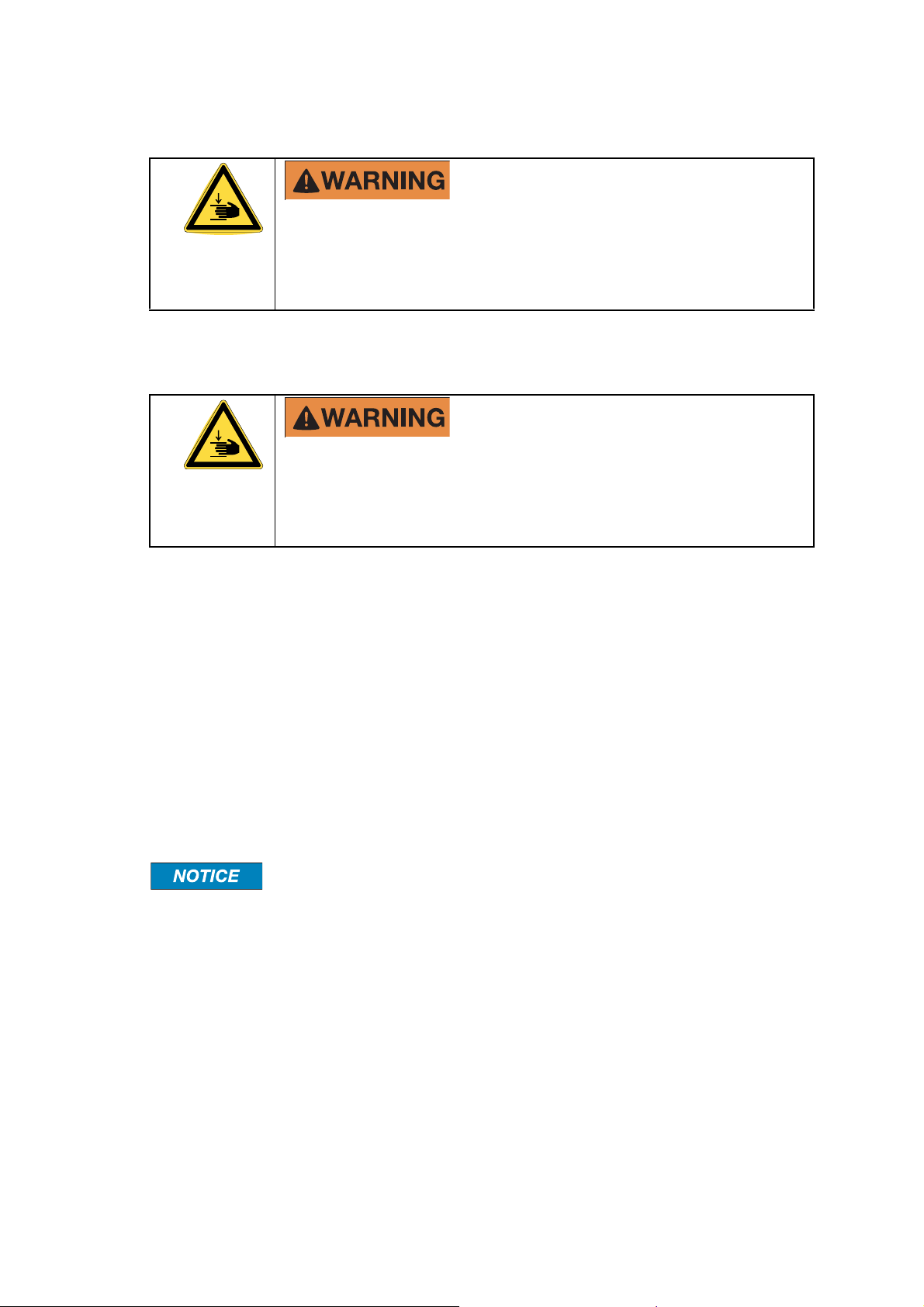
Quick stroke movements of the stitching heads!
Danger of crushing!
¾Before carrying out maintenance or repairs, take care that the power supply is switched off
and prevented from being switched on again accidentally.
¾Never operate the system without properly mounted finger guard.
1.11 Servicing and repair work, elimination of faults
Quick stroke movements of the stitching heads!
Danger of crushing!
¾Before carrying out maintenance or repairs, take care that the power supply is switched off
and prevented from being switched on again accidentally.
¾Never operate the system without properly mounted finger guard.
Basic safety precautions
Mount the finger guard again after adjustment-, maintenance- and inspection work.
1.12 Structural modifications to the machine
Changes to the machine, additions or modifications may only be undertaken with the permission of
the manufacturer.
1.13 Cleaning the machine and the removal of waste products
The functionality of the machine and clean processing of the products can only be guaranteed over
a prolonged period of time, if the machine is regularly cleaned in accordance with the normal methods used in mechanical engineering.
Clean with mild, non-abrasive and non-scratch cleaners. Never use aggressive cleaning agents
such as e.g. solvents.
While doing this, it is particularly important to remove trimmed paper remnants
and paper dust regularly, as these can result in jamming of the machine and in
increased wear of its parts.
The machine contains bare metal parts. These should be cleaned regularly with a protective cleaning agent, especially when using the machine in rooms of high air humidity.
All substances and materials used (e.g. solvents and lubricants) must be handled appropriately and
removed in an environmentally friendly way.
1.14 Noise levels produced by the machine
The noise emitted by the machine when it is running does not exceed a value of 81 dB(A) as measured in accordance with DIN 45635, Part 27.
Hohner Maschinenbau GmbH EXACT-PLUS 10/2010 7
Page 8
Description of the stitching machine EXACT-PLUS
2 Description of the stitching machine EXACT-PLUS
2
1
4
1
Fig. 2.1
3
8 EXACT-PLUS 10/2010 Hohner Maschinenbau GmbH
Page 9

Description of the stitching machine EXACT-PLUS
2.1 Safety-related components
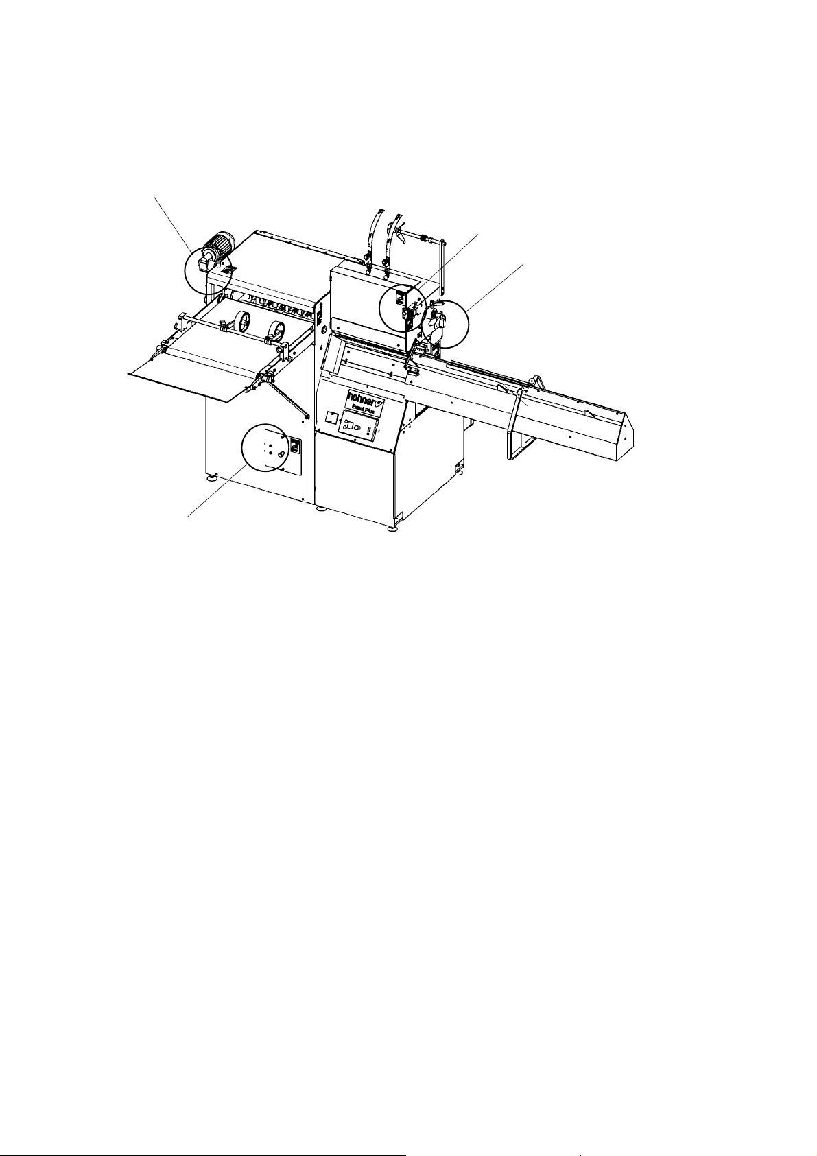
- Fig. 2.4 -
2.1.1 Position of the cut-out switch / emergency switch
The operator of the machine EXACT-PLUS is extensively protected by covers and shells from any
danger. The main danger sources are additionally guarded against by special danger signs and
appliances (cut-out switches).
2.1.2 Stitching aggregate
When installing or adjusting stitching heads the front cover has to be open. The front cover is electrically locked with the cut-out switch -1-, i.e. the machine cannot be operated with open front
cover.
2.1.3 Delivery
Adjustment of paper stop (see 3.10) or installation at the delivery has to be done when plastic cover
is open. The plastic cover is electrically locked with the cut-out switch -2-, i.e. the machine cannot
be operated with open plastic cover.
2.1.4 Staggered stitch
To change-over from standard to "staggered stitching" remove the protecting cover. The protecting
cover is electrically locked with the cut-out switch -3-, i.e. the machine cannot be operated with
open protecting cover.
2.1.5 Main switch and emergency switch
Before all repairs and adjustments on the machine cut out the main switch -4-.
Hohner Maschinenbau GmbH EXACT-PLUS 10/2010 9
Page 10
Description of the stitching machine EXACT-PLUS
1
2
Fig. 2.2
Fig. 2.3
3
4
5
10 EXACT-PLUS 10/2010 Hohner Maschinenbau GmbH
Page 11

Description of the stitching machine EXACT-PLUS
2.2 Electrical connections
Voltage
Danger of electrical shock!
¾ Only qualified skilled workers may carry out work in the vicinity of the mains
power supply.
- Employ a specialist to connect the machine to the mains supply. The local connection regulations
must be adhered to. The cable should not lie loosely on the ground after it has been laid.
Specifically observe the direction of rotation of the motor shaft (visible at the vane
marked by the red arrow, see Fig. 3.9). Direction can be reversed by exchanging
2 phases in the mains supply cable.
2.3 Motor protective relay
- Fig. 2.2 -
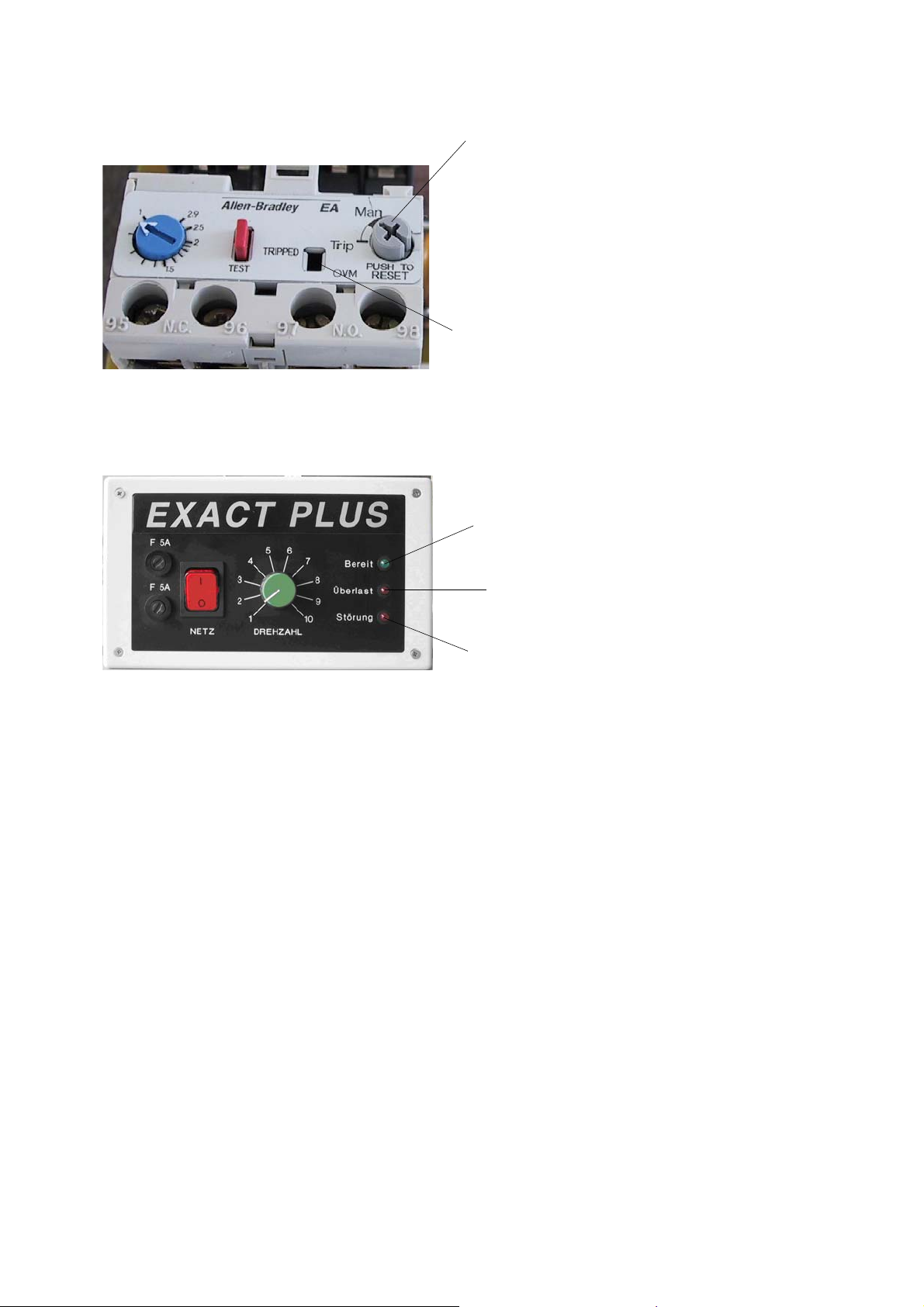
The motor protective relay is triggered upon overload of the motor and switches off the power supply of the motor. This is indicated on the trigger display window -2-.
• Yellow display, invisible: relay not triggered
• Yellow display, visible: relay triggered
- Should the motor protective relay have triggered, the machine must first be switched off with the
ON/EMERGENCY-STOP button. Then determine and eliminate the cause.
Once the cause has been eliminated, the motor protective relay can be reset by
pressing the reset key -1-, - Fig. 2.2 -.
While doing so, ensure that all protective systems are installed on the machine
and all tools have been removed from the machine.
2.4 Block mode for drive motor sliding connecting rods
- Fig. 2.3 -
Disconnection of the three-coil regulation of the DC motor occurs when the motor has been blocked
for 10 sec.
The block mode is set back by switching off the mains voltage.
•-3-, Green
Illuminated when the mains voltage is adjusted and released (ready).
•-4-, Red
Illuminated when the current limit has been reached (overload).
•-5-, Red
Illuminated once the block protection has switched off the controller (fault)
Hohner Maschinenbau GmbH EXACT-PLUS 10/2010 11
Page 12
Description of the stitching machine EXACT-PLUS
1
Fig. 2.4
12 EXACT-PLUS 10/2010 Hohner Maschinenbau GmbH
Page 13

Description of the stitching machine EXACT-PLUS
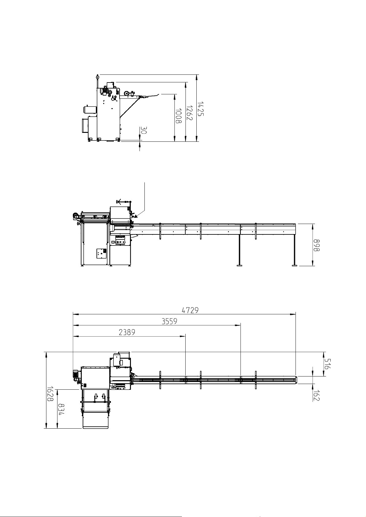
2.5 Dimensions
- Fig. 2.4 -
2.6 Conformity
Please observe the document attached:
„EC Declaration of Conformity according to the EC Machinery Directive 2006 / 42 / EC“
2.7 Marking and type plate
The type plate and the CE labelling are fitted below the main switch - Fig. 2.4 -, Pos. 1.
2.8 Technical data
Smallest brochure size 110 x 80 mm*
Largest brochure size 430 x 340 mm*
Max. setting dimension for narrow stitching heads, approx 330 mm
Stitching capacity, staples per hour, approx: 4,000*,
continuously variable
Staple displacement by "staggered stitch",
from staple middle to staple middle:
crown width of a staple See stitching head operating
Gross weight, machine with 2-station 511 kg
Net weight, machine with 2-station 315 kg
Kind of current, motor standard execution Geared motor
Total wattage of the motor, approx 1 kW
Noise emission under 81 dB(A)
18 mm
instructions
Three-phase A.C.
230/400 V
50-60 Hz
STITCHING AGGREGATE
Max. 4 hohner - narrow stitching heads can be mounted for standard stitching,
for loop-stitching or mixed
Stroke-Narrow Stitching Head: 50 mm
Stroke-clincher back pressure: 5,5 mm
Stitching thickness-standard stitching, max See stitching head
operating instructions
Stitching thickness-loop stitching, max See stitching head
operating instructions
Stitching wire for standard stitching See stitching head
operating instructions
Stitching wire for loop-stitching See stitching head
operating instructions
* depending on nature and quality of the paper
Hohner Maschinenbau GmbH EXACT-PLUS 10/2010 13
Page 14

Description of the stitching machine EXACT-PLUS
14 EXACT-PLUS 10/2010 Hohner Maschinenbau GmbH
Page 15
Description of the stitching machine EXACT-PLUS
2.9 Accessories
2.9.1 Equipment
Art.-no. 99 46 592 2 centering devices
Art.-no. 99 64 083 2 centering devices
2.9.2 Tools
Art.-no. 46 00 002 1 screwdriver, SB 2,3
Art.-no. 46 00 003 1 screwdriver, SB 4,5
Art.-no. 46 00 004 1 screwdriver, SB 7
Art.-no. 46 00 014 1 diagonal nipper
Art.-no. 46 00 033 1 hexagon socket screw key no. 4 x 150 (T-
handle)
Art.-no. 46 00 039 1 Torx screwdriver T20 (T-handle)
Art.-no. 46 00 042 1 Torx screwdriver T10 (T-handle)
Hohner Maschinenbau GmbH EXACT-PLUS 10/2010 15
Page 16
Installation and commissioning of the machine
3 Installation and commissioning of the machine
Fig. 3.1
16 EXACT-PLUS 10/2010 Hohner Maschinenbau GmbH
Page 17

Installation and commissioning of the machine
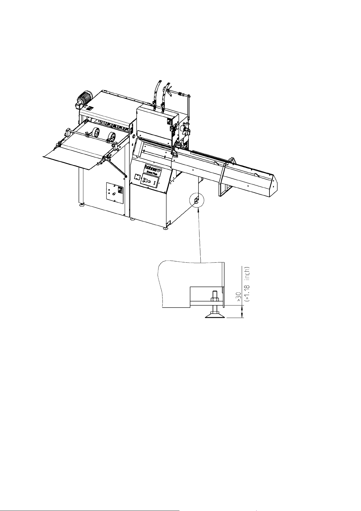
3.1 Installation
- Fig. 3.1 -
The machine must stand on even floor, the table should be positioned horizontally.
3.2 Mounting - stitching head
See stitching head operating instructions.
Hohner Maschinenbau GmbH EXACT-PLUS 10/2010 17
Page 18
Installation and commissioning of the machine
10
8
7
9
14
1
5
11
12
Fig. 3.2
18 EXACT-PLUS 10/2010 Hohner Maschinenbau GmbH
Page 19

Installation and commissioning of the machine
3.3 Mounting - clincher box
- Fig. 3.2 -
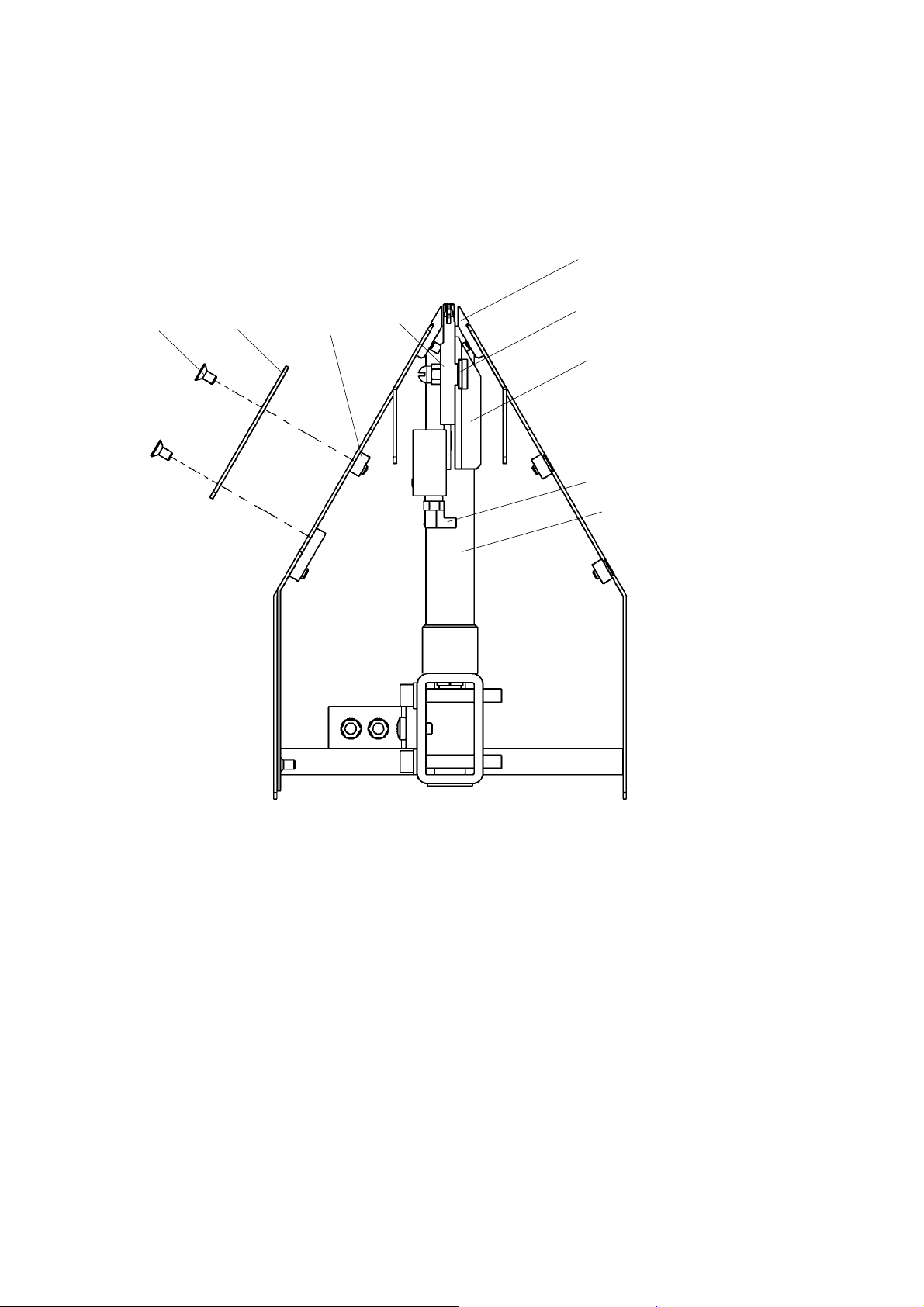
- Take away the mounting plate -7-. Unscrew the four slotted countersunk head screws -8-.
- Install by turning slightly the clincher box -14- with pusher, behind the intermediate ledge -9-. Turn
the clincher box again and place it on the top between the both supporting ledges -10-.
- Place the shaft of the hexagon socket set screw on the rear side of the clincher box in the groove
provided in the receiver girder -5-.
- At the same time make sure that the pusher block -11- fits into the groove of the main
drive bar -12-.
- Put the hexagon socket screws -13- through the oblong hole in the gliding strip into the mounting
block -1- (push the mounting block first into the fixing groove of the receiver girder -5-).
- Tighten both hexagon socket screws -13- slightly by using the delivered hexagon socket screw
key SW 4 (with T-handle) and move the clincher box laterally under the corresponding stitching
head.
After this, the fine adjustment has to be done (see 3.4).
Hohner Maschinenbau GmbH EXACT-PLUS 10/2010 19
Page 20
Installation and commissioning of the machine
15
16
14
17
13
Fig. 3.3
15
14
18
19
20 EXACT-PLUS 10/2010 Hohner Maschinenbau GmbH
Page 21

Installation and commissioning of the machine
3.4 Fine adjustment - clincher box
- Fig. 3.3 -
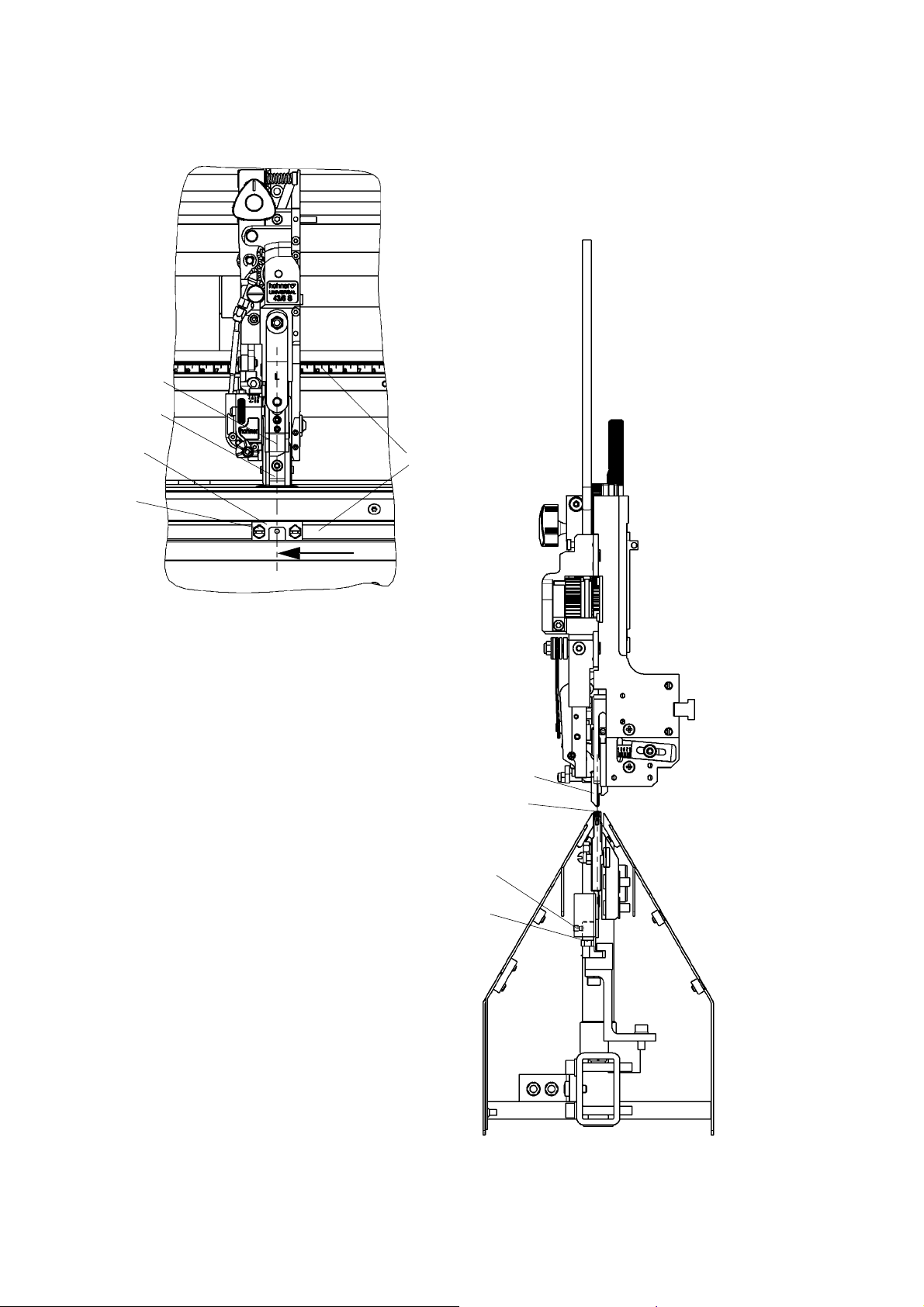
The middle of the driver -15- and bender -16- must be exactly in the middle of the clincher box -14(see arrows)!
- Now, rotate the unit by hand (see 3.12), until the driver and the bender are just over the clincher
box. Adjust the middle of the clincher box of the driver and tighten both
hexagon socket screws -13-.
Additional assistance by scales -17-
TIP
The right edges of stitching head and clincher box must be adjusted on the same scale setting -17-.
3.5 Pressure adjustment - clincher back press
- Fig. 3.3 -
- Loosen the hexagon socket set screw -18-, turn the hexagon head screw -19-
counter clockwise to increase pressure or
clockwise to decrease pressure.
- Then re-secure the hexagon socket set screw -18-.
The groove-middle of the driver -15- and the middle of the clincher box -14- must
coincide absolutely
Hohner Maschinenbau GmbH EXACT-PLUS 10/2010 21
Page 22
Installation and commissioning of the machine
21
Fig. 3.4
20
22 EXACT-PLUS 10/2010 Hohner Maschinenbau GmbH
Page 23

Installation and commissioning of the machine
3.6 Mounting and adjustment - guiding brushes / guiding angle
- Fig. 3.4 -
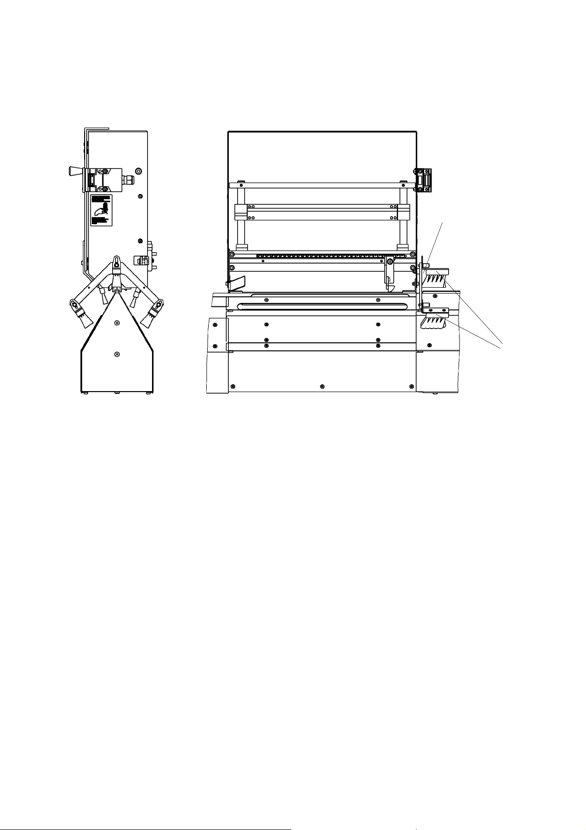
To insert brochures under stitching heads use guiding brushes -20- and guiding angle-21-.
They are destined to stop every brochure at the same position and to ensure that projecting sheets
are made flush.
The guiding angle -21- effects that sheets or brochures not will be jammed during feeding into the
stitching unit.
Installation and adjustment has to be effected when stitching head covering is open. The machine
can not be operated at the same time (see 2.1.2).
3.7 Mounting - centering device and guiding cam
See stitching head operating instructions.
Hohner Maschinenbau GmbH EXACT-PLUS 10/2010 23
Page 24
Installation and commissioning of the machine
35
34
Fig. 3.5
37
36
Fig. 3.6
38
39
24 EXACT-PLUS 10/2010 Hohner Maschinenbau GmbH
Page 25

Installation and commissioning of the machine
3.8 Adjustment - stitching thickness at the stitching aggregate
- Fig. 3.5 -
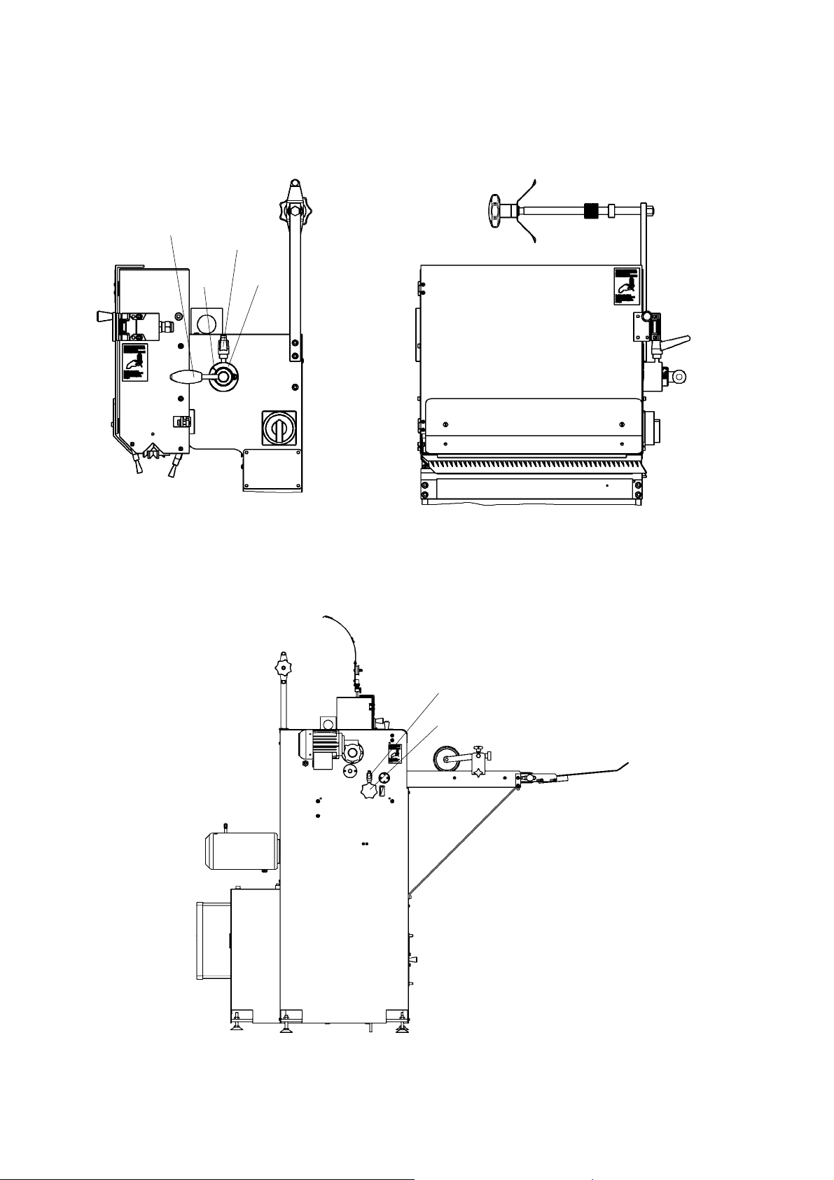
- Loosen clamping lever -34-, now the needed stitching thickness can be adjusted with the adjusting lever -35- by means of the graduated dial -36- and the graduation mark -37-.
- Retighten the clamping lever -34-. When working with special paper material a correction will be
necessary.
3.9 Adjustment - stitching thickness on the delivery
- Fig. 3.6 -
In addition to the stitching aggregate the corresponding stitching thickness is also to be adjusted at
the delivery.
- Loose the clamping lever -38-, adjust the pressure of the rolls in the delivery according to the brochure by turning the star handle -39- (visible through plastic cover on the top).
Adjustment control
Pressure of rolls too low = brochure is not ejected
Pressure of rolls too high = knocking noise in the delivery
Hohner Maschinenbau GmbH EXACT-PLUS 10/2010 25
Page 26
Installation and commissioning of the machine
Fig. 3.7
43
40
41
42
26 EXACT-PLUS 10/2010 Hohner Maschinenbau GmbH
Page 27

Installation and commissioning of the machine
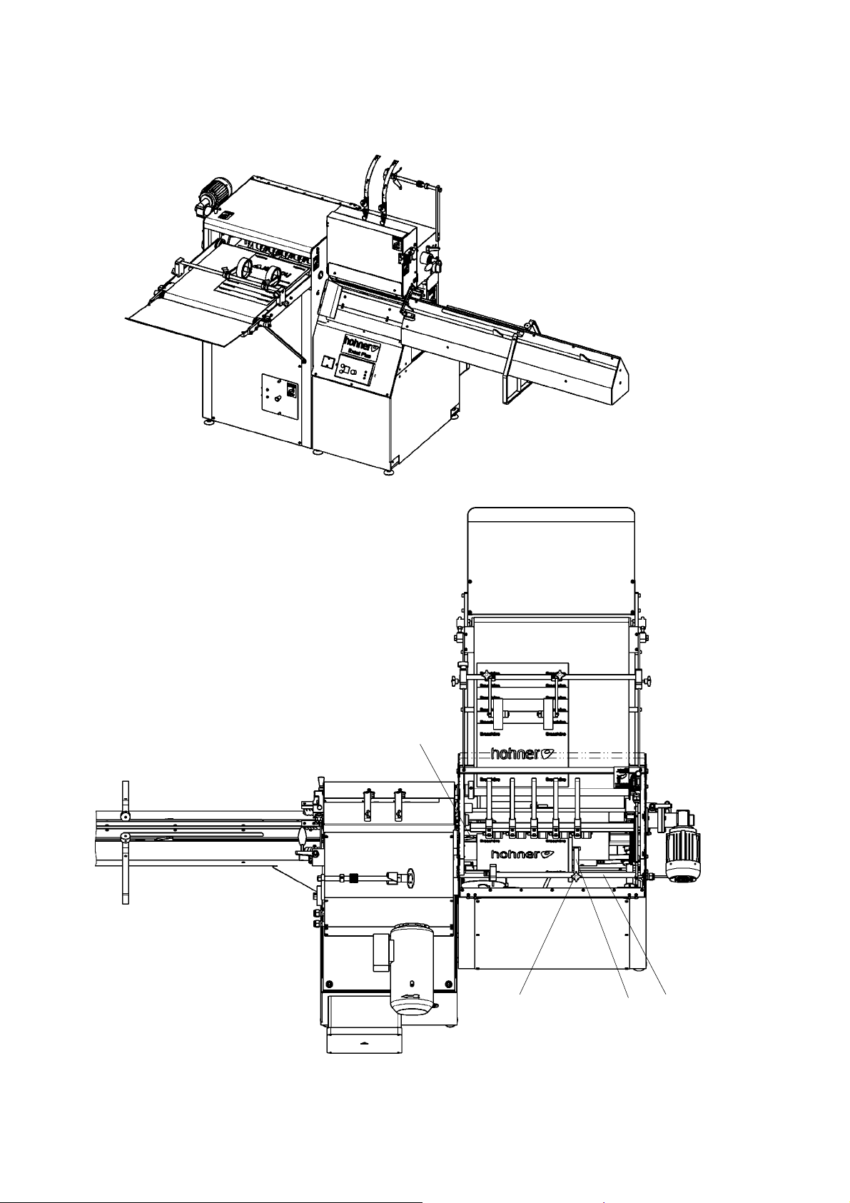
3.10 Adjustment - paper stop in the delivery
- Fig. 3.7 -
To obtain an exact scale tile delivery the paper stop in the scale tile delivery has to be adjusted to
the corresponding brochure thickness.
- First open the plastic sight glass.
It is electrically locked and prevents the machine from operating during the adjustment of the paper
stop.
As you can see on the illustration, the adjustment can be effected from the top.
- By loosening the star handle screw -40- and the adjusting ring -41- the complete paper stop can
be moved on the guiding rod -42-.
- Adjustment has to be effected in this way that the brochure, between carrier -43- and the paper
stop has some free motion (danger of jolt).
- Re-tighten star handle screw -40-.
When changing brochures from small to big the paper stop has first to be
adjusted
- danger of jolt -
Hohner Maschinenbau GmbH EXACT-PLUS 10/2010 27
Page 28
Installation and commissioning of the machine
50
48
49
47
44
45
46
Fig. 3.8
28 EXACT-PLUS 10/2010 Hohner Maschinenbau GmbH
Page 29

Installation and commissioning of the machine
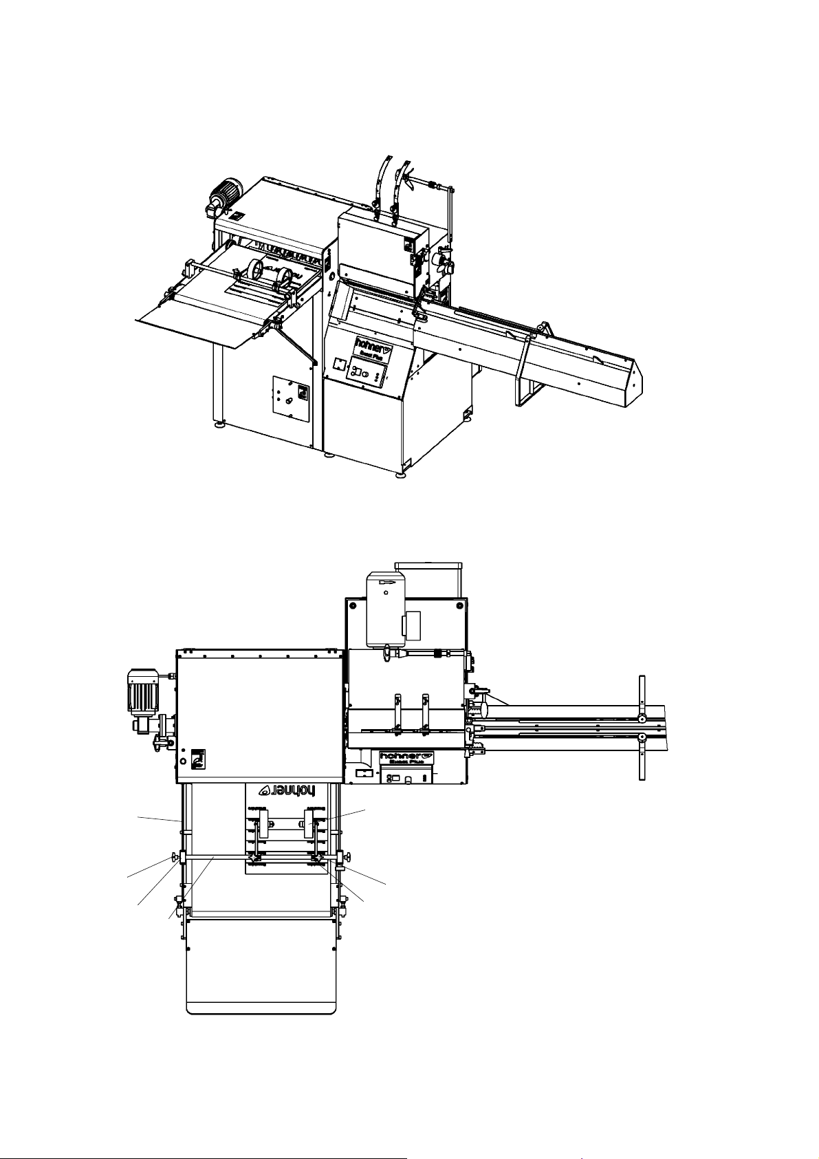
3.11 Adjustment - guiding rollers on the delivery table
- Fig. 3.8 -
In order to obtain an exact sit-close scale tile delivery on the delivery table both guiding rollers -44have to be adjusted to the size of brochure (see illustration, top view).
- Loose the upper star handle screws -45- and move roll holders -46- on the axe -47- sidewards
until both guiding rollers -44- are approximately centrical to the thickness of the brochure.
- Retighten upper star handle screws -45-.
- Loosen star handle screws -48- at the side, move both supports -49- at the same time on the
guide bars -50- so far, that the brochure is falling exactly between conveying belt and guiding rollers.
- Re-tighten star handle screws -48- at the side.
Hohner Maschinenbau GmbH EXACT-PLUS 10/2010 29
Page 30
Installation and commissioning of the machine
52
51
53
Fig. 3.9
30 EXACT-PLUS 10/2010 Hohner Maschinenbau GmbH
Page 31

Installation and commissioning of the machine
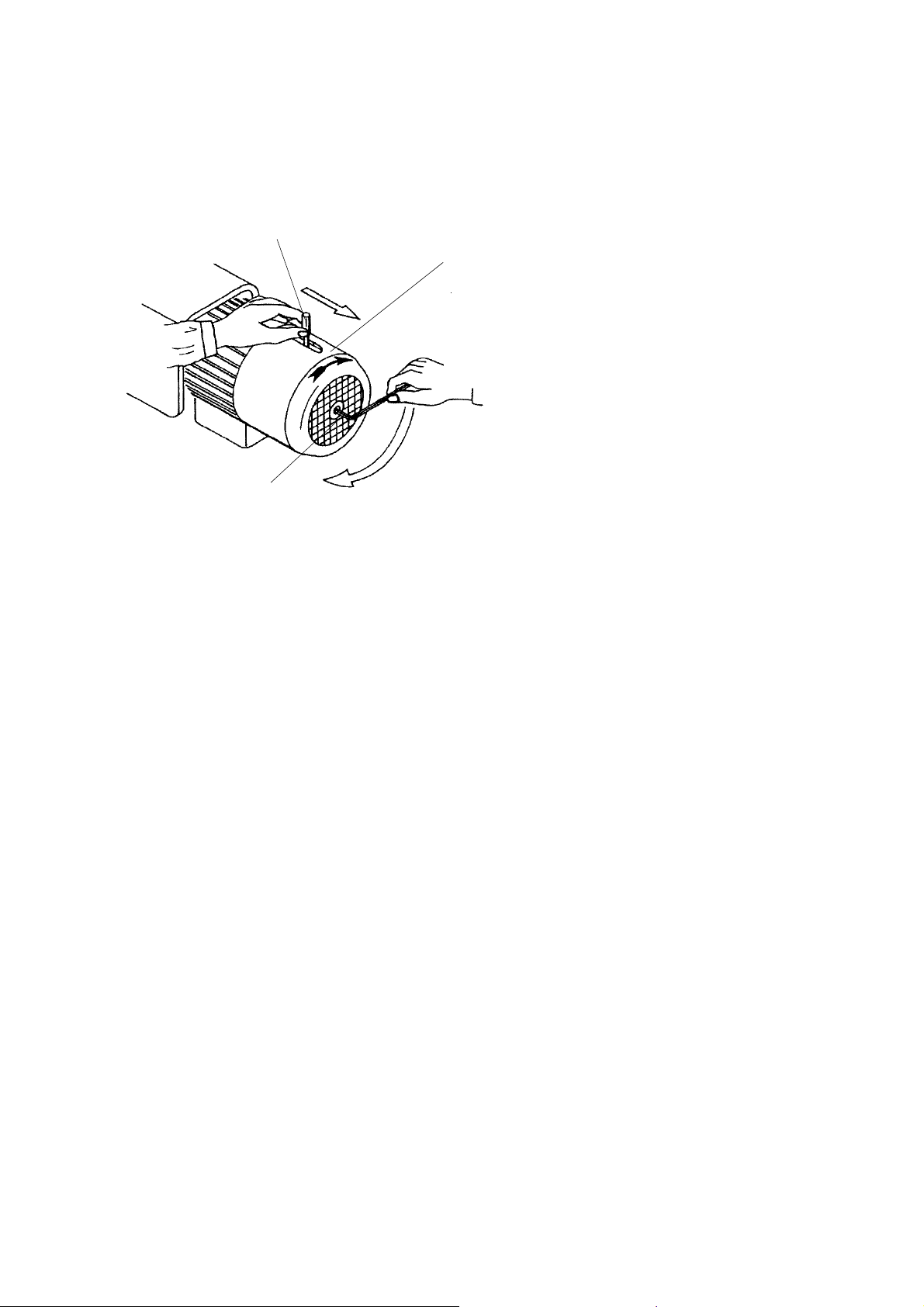
3.12 Adjust by hand - stitching head actuation
- Fig. 3.9 -
Before carrying out maintenance or repairs, take care that the power supply is
switched off and prevented from being switched on again accidentally.
For any adjustment or installation work at the stitching aggregate the stitching head driving elements can be adjusted by hand. For this step use the enclosed long hexagon socket screw
key no. 5.
Put the hexagon socket screw key -53- in the cylindrical screw at the back of the drive motor -51- in
the ventilator shaft. Now you can use it as a crank. Press ventilator lever -52- for brake. Turn with
the screw key in direction of arrow.
Before resumption of work the hexagon socket screw key -53- has to be
removed.
Hohner Maschinenbau GmbH EXACT-PLUS 10/2010 31
Page 32
Installation and commissioning of the machine
43
54
55
Fig. 3.10
32 EXACT-PLUS 10/2010 Hohner Maschinenbau GmbH
Page 33

Installation and commissioning of the machine
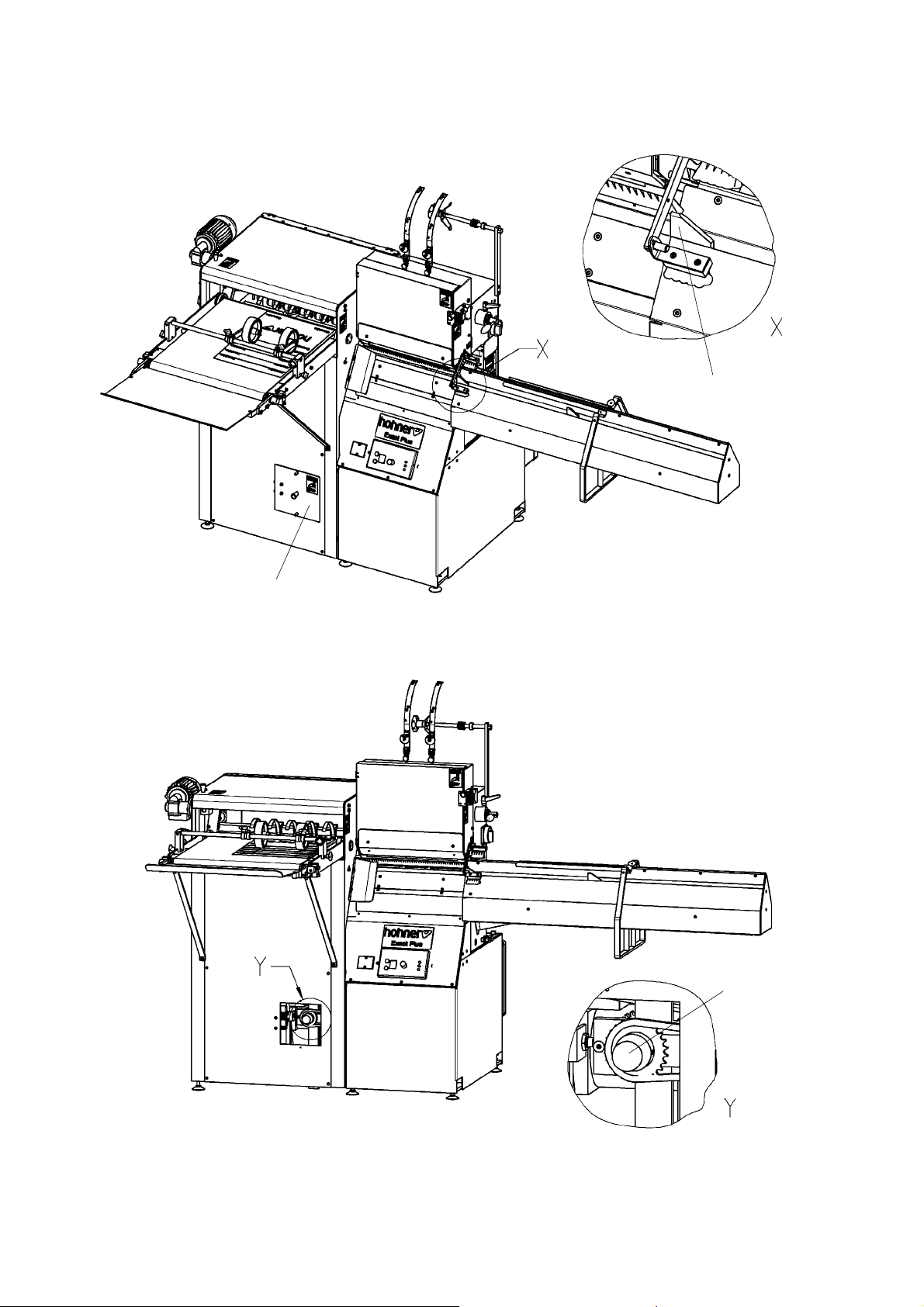
3.13 Adjustment - "staggered stitch"
- Fig. 3.10 -
In order to avoid a one-sided thickening on the side of the staple when stacking or cutting, the
machine can be adjusted on "staggered stitch"
TIP
Adjustment:
- The brackets -43- should be placed in about the left final position.
- Switch off the machine, resp. interrupt the current supply.
- Open the protection cap -54- in the front plate under the delivery.
- Pull the visible red adjusting knob -55- by hand and release it in this way.
- If you turn it a fourth (90°) to the left or to the right, the machine is adjusted from "staggered stitching" to standard stitching and vice versa.
- Make sure that the red adjusting knob -55- locks after adjustment or releasing.
- Shut the protecting cap -54-.
During the adjustment the machine can not be operated (see 2.1.4).
Before carrying out maintenance or repairs, take care that the power supply is
switched off and prevented from being switched on again accidentally.
Hohner Maschinenbau GmbH EXACT-PLUS 10/2010 33
Page 34
Installation and commissioning of the machine
3
4
3
4
Fig. 3.11
34 EXACT-PLUS 10/2010 Hohner Maschinenbau GmbH
Page 35

Installation and commissioning of the machine
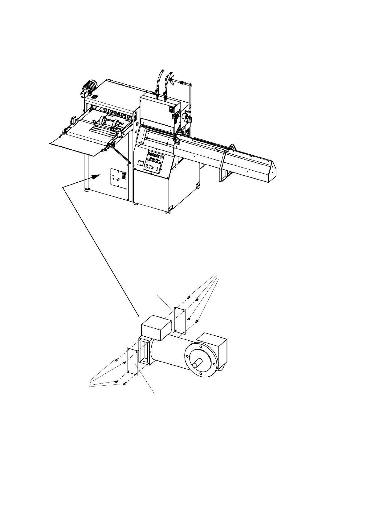
3.14 Carbon brushes and switch-off brushes
- Fig. 3.11 -
- After remove clamping strap -3- by loosening screws -4- from the end housing on the B side. The
carbon brushes can be easily replaced and adjusted.
The brushes must always be replaced with the same brush type supplied with the motor.
The quality of the carbon brushes is designed in each case to meet the specific requirements for
normal voltages and closed-loop control or small voltages. Creepage current is prevented through
the use of collector-cleaning carbon brushes and brush yokes with plastic rings. In the case of good
commutation, brush service lives of approx. 3000-5000 operating hours can be achieved for continuous duty S 1.
Hohner Maschinenbau GmbH EXACT-PLUS 10/2010 35
Page 36

Flow diagrams
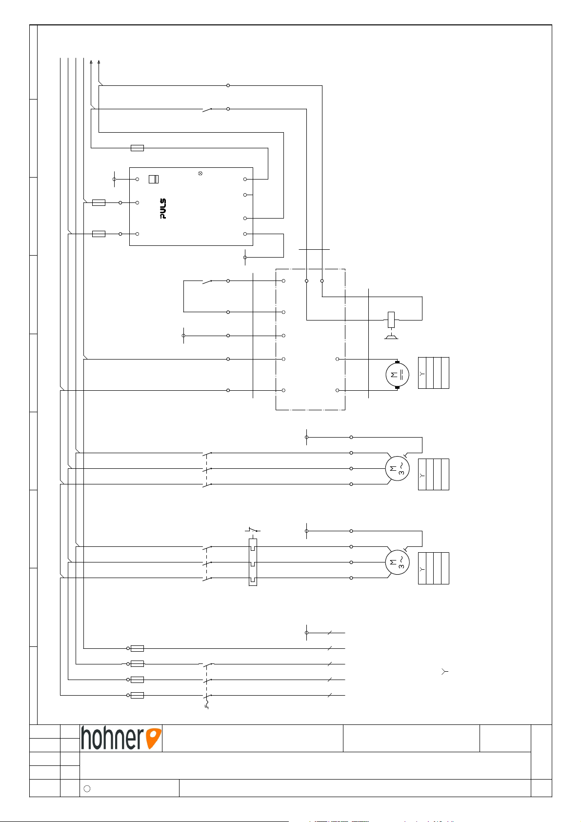
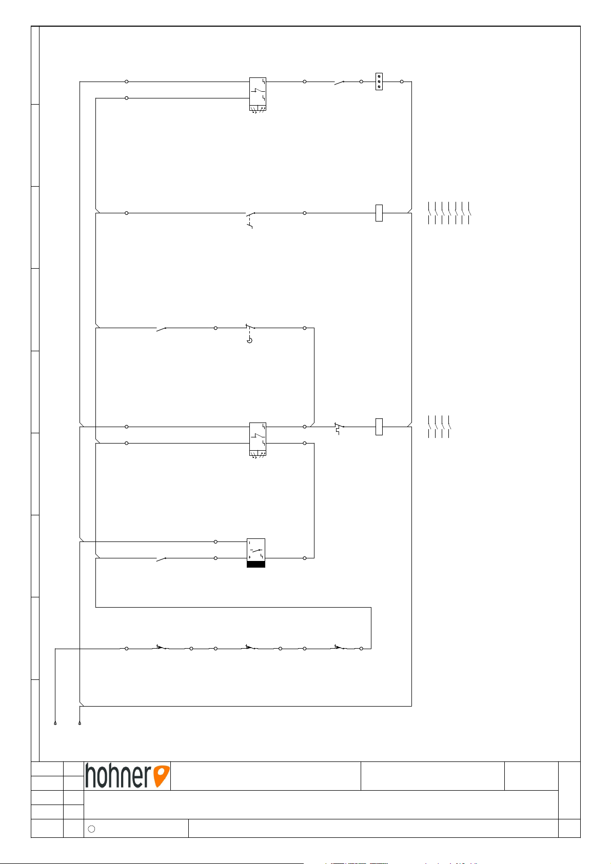
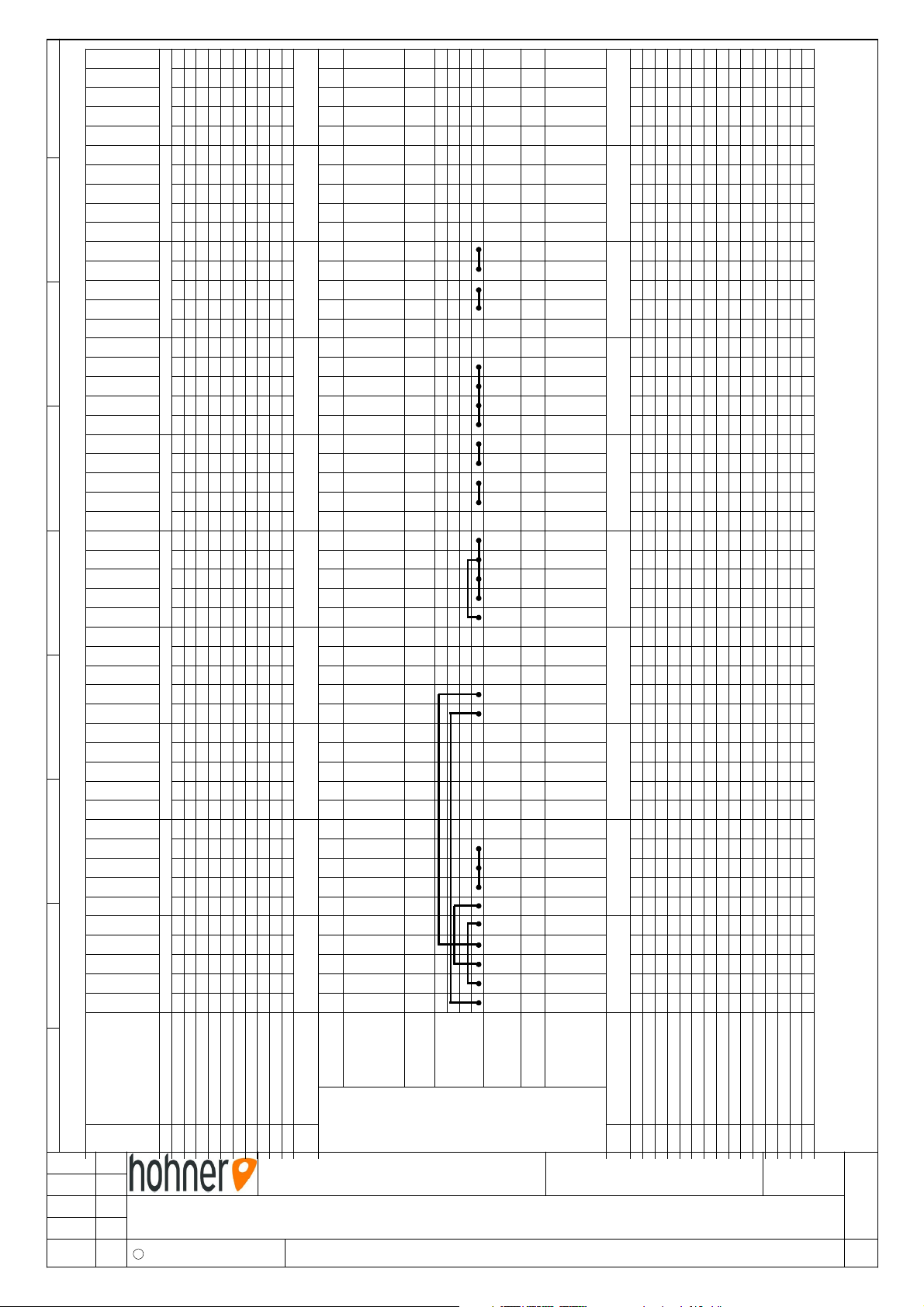
4 Flow diagrams
EXACT-PLUS no. 43 40 935 P. 1 - 4
400 / 415 V 3 x AC Y 50/60 Hz
EXACT-PLUS np. 43 40 936 P. 1 - 4
220 / 230 V 3 x AC
U 50/60 Hz
36 EXACT-PLUS 10/2010 Hohner Maschinenbau GmbH
Page 37
L1L2L3
/2.1
/2.1
L+
L-
N
13
14
X1 17 18
2.7
K2
F3
2,0A
PE
6
X1 5
F2
T2,0A
230
PE
DC ok
N
AC 11 5/230V
L
-G1
3A,72W
ML70. 100
Uout= 24VDC
Adj. 24-28V
Powe r Supply
63
K2
PE
5
3
1
K2
+
+
-
DC 24 V
-
PE
64
16
6
2.7
15
5
PE
PE
14
2
1
X1 13
-W1
ÖLFLE X CLASS IC 100
6
4
2
2.7
7x1,0 0mm²
-W1
3
4
X2:6
X1
X2
X2:5
X1:PE
X1:4
X1:3
A-
L3/N
L1
X1:6
A+
X1:5
A1
PE
4
L+
3
L-
Y1
2
A+ A-
1
180 V/DC
M3
-W2
5x1,0 0mm²
PE
12
11
10
U V W
pe
400 V
M2
Steuertrafo
control transformer
transformateur de commande
Bremse
brake
frein
2,5 A
0,35kW
contenu-
sliding rods
Schiebegestänge
Gleichstrommotor-
direct current motor-
0,45 A
0,12kW
Auslagemotor
motor-delivery
tringles coulisse
moteur à courant
moteur-étalage
1 2 3 4 5 6 7 8 9
26.11.08 SC1
Änderun g Name
5
6
3
4
1
2
2.5
K1
4
6
3
2
X1 1
F1
T6,3A
Maschi ne / Machine / Machine
5
4
3
2
1
Q1
20 A
EXACT-PLUS
400/415V 3xAC Y 50/60Hz
Bennenu ng / Title / Dénomination
Schaltplan - flow diagram -schéma des circuites
C Hohner Maschinenbau GmbH
95
96
2.5
5
6
3
4
1
2
F4
1,0A
1-2,9 A
PE
PE
PE
9
8
U V W
X1 7
GNYE
PE
BU
N
GY
L3
BK
L2
BN
L1
Zeichnungs-Nr. / Drawing-Nr. / Dessin-No. Index
pe
1,0 A
400 V
0,37kW
M1
400 / 415 V
3 x AC 50/60Hz
43 40 935
head
piquage
Heftkopfmotor
Netzanschluss
moteur-tête de
motor-stiching-
main supply
au réseau
rattachement
d
Seite
Sheet
Page
1
Page 38
73
74
x1
21
31
BU
GY
WS
BN
+ -
+
39
.7
K2
x2
X1 40
X1 22
H1
Summenzähler
compteur-
adding counter
totalisateur
B3
23
24
X1 30
38
S5
13
14
.5
K1
21
33
22
37
S4
A1
A2
1 2
3 4
5 6
13 14 .3 53 54
63 64 .9 73 74
Heften ein
K2
1.4
1.4
1.4
1.8
1.6
stiching on
piquage marche
top
oben
Heftkopf
stiching head
en haut
tête de piquage
95
96
A1
20
X1 29
BU
GY
BN
WH
+ -
+
36
35
1.3
F4
A2
1 2
3 4
5 6
13 14
K1
.6
1.2
1.3
1.3
Papier
vorhanden
paper existing
papier existant
B2
BU
19
53
54
.7
K2
11
12
X1 23
X1 24
S1
BN
32
11
X1 25
BK
34
B1
12
X1 26
S2
11
12
X1 27
X1 28
S3
Heftposition
stiching position
position de piquage
switch
cut-out
schalter
Sicherheits-
autom.
coupe-circuit
1 2 3 4 5 6 7 8 9
L+
1.9/
19.05.08 SC1
Änderun g Name
L-
1.9/
Maschi ne / Machine / Machine
400/415V 3xAC Y 50/60Hz
Bennenu ng / Title / Dénomination
Schaltplan - flow diagram -schéma des circuites
C Hohner Maschinenbau GmbH
EXACT-PLUS
Zeichnungs-Nr. / Drawing-Nr. / Dessin-No. Index
43 40 935
d
Seite
Sheet
Page
2
Page 39
2/9
2/9
2/7
2/6
2/5
2/4
2/3
2/6
2/3
2/9
2/7
2/4
2/2
2/2
2/2
2/2
2/2
2/2
2/9
2/9
2/5
2/3
1/9
1/9
1/6
1/6
1/5
1/5
1/4
1/4
1/4
1/3
1/3
1/3
1/6
1/4
1/3
1/8
1/7
1/2
1/1
1/1
1/1
74K240X1H1
73K239GYB3
A1K23824S5
3722S4
95F436GYB2
35WHB2
34BKB1
14K13321S4
54K232BNB1
13K131
WHBN
3023S5
29BNB2
53K22812S3
2711S3
2612S2
2511S2
2412S1
13K22311S1
22X2H1
21BUB3
20BUB2
A2K219BUB1
-G118L-A1/Y1
14K217L+A1/Y1
64K2166A1
63K2155A1
144A1
133A1
6K212WM2
4K211VM2
2K210UM2
6F49WM1
4F48VM1
2F47UM1
PEPEPEA1
PEPEPEM2 / S5
PEG1PEPEPEPE / M1
400G1F26
0G1F25
F14N
6K1F136Q1
3K1F124Q1
1K1F112Q1
supply
Anschl uß
unité
Gerät
recco rdement
binder name
appli ance
Klemm enname
pont
brigde
Brüc ken
nom de la borne
supply
Anschl uß
recco rdement
numero borne
binder number
Klemm ennummer
1
GY
BU
2
GY
WH
BK
1
B3
4
3
6
5
2
1
3
2
1
3
2
1
YE
GN
YE
GN
YE
GNYEGN
BU
BK
BN
BK
unité
Gerät
appli ance
BN
BN
WH
BN
BN
2
1
2
1
2
1
2
BU
BU
BU
YE
GN
vert/ jaune
blanc
green/Yellow
white
WH = weiß
GNGE = grün/gel b
bleu
gris
blue
gray
BU = blau
GY = grau
noir
brun
black
brow n
1 2 3 4 5 6 7 8 9
19.05.08 SC1
Änderun g Name
Maschi ne / Machine / Machine
EXACT-PLUS
400/415V 3xAC Y 50/60Hz
Bennenu ng / Title / Dénomination
Klemmleiste - connector block -réglette de bornes
C Hohner Maschinenbau GmbH
X1
Ziel / dest. / fin.
Q1M1M2A1S1S2S3B1B2S4S5B3H1
123456789
Nr.
Zeichnungs-Nr. / Drawing-Nr. / Dessin-No. Index
101112
43 40 935
BK = schwarz
13
BN = braun
d
Seite
Sheet
Page
3
Page 40
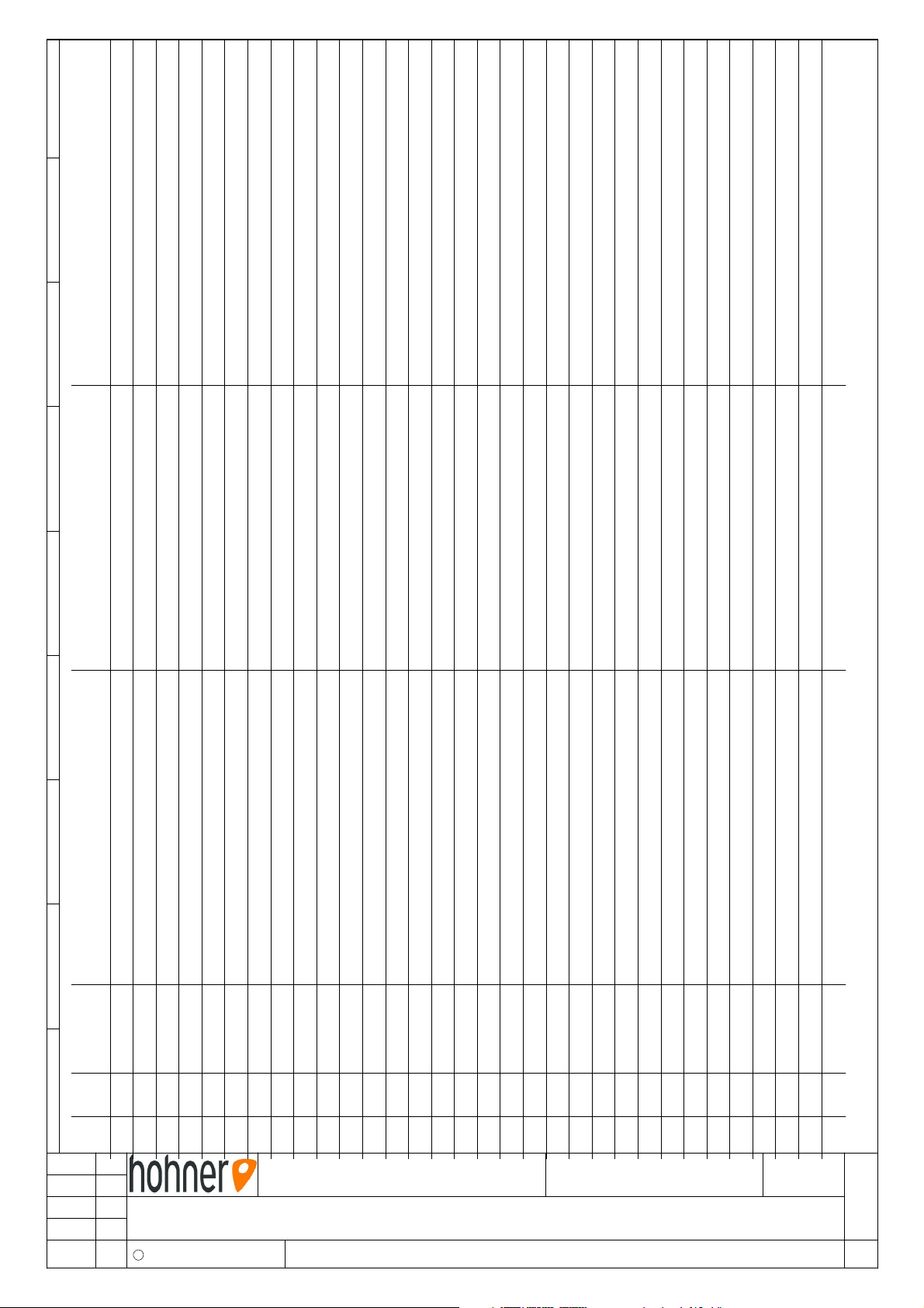
Description
interrupteur principal (interr. dúrgence)
coupe - circuit autom. porte
coupe - circuit autom. couvercle / étalange
coupe - circuit autom. couver de étalage
tôle de protection/étalage
interrupteur f. de course, tête de piquage
commande par pédale
détecteur de proximeté
tringles coulisse
reflet barrage photoélectrique
reflet barrage photoélectrique
convertisseur M3
frein M3
transf. de commande avec redesseur courant
compeur totalisateur (spécial)
fusibles de sécurité-cir. principal T6,3 A
fusibles de sécurité-transformateur
primaire T2,0 A
fusibles de sécurité-commande T2,0 A
Description
main switch (emergency switch)
cut-out, autom. switch door
cut-out, autom. switch prot. cover
delivery
cut-out, autom. switch cover plate/
delivery
micro-switch stiching head
pedal switch
proximity switch-sliding rods
fluidic light barrier
fluidic light barrier
power converter M3
brake M3
control transformer with rectifier
adding counter (special)
saftey fuses-main circuit T6,3 A
saftey fuses-transformer
primary T2,0 A
saftey fuss-electic circuit
contacteur tête de piquage
contacteur moteur-étalage
bloc contact de secours 40DILE
moteur-tête de piquage
moteur-étalage
moteur à courant contenu-tringles coulisse
relais de surchargé
adaptateur
réglette de bornes
control T2,0 A
contactor stiching head
contactor motor-delivery
auxiliary contact-block 40DILE
motor-stiching head
motor-delivery
direct current motor-sliding rods
overload relay
adapter
connector block
Bezeichnung
1 2 3 4 5 6 7 8 9
Bez. Art. Nr.
Pos.
26.11.08 SC1
Änderun g Name
Hauptschalter (Not-Aus)
Sicherheitsschalter Türe
43 00 770
43 00 004
S1
Q1
1.1
2.2
Sicherheitsschalter Abdeckblech/Auslage
Sicherheitsschalter Schutzhaube/Auslage
43 00 004
43 00 004
S2
S3
2.2
2.2
Endschalter Heftkopf
Fußschalter
Näherungsschalter Schiebegestänge
43 00 271
43 00 068
43 00 771
S4
S5
B1
2.6
2.7
2.3
Maschi ne / Machine / Machine
400/415V 3xAC Y 50/60Hz
Bennenu ng / Title / Dénomination
Ersatzteile - spare parts - pièces de recange
C Hohner Maschinenbau GmbH
Reflexlichtschranke
Reflexlichtschranke
Stromrichter M3
43 00 381
43 00 381
43 00 512
B2
B3
A1
2.4
2.9
1.5
EXACT-PLUS
Bremse M3
Steuertrafo mit Gleichrichter
Summenzähler (Sonder)
Sicherung Hauptstromkreis T6,3 A
Sicherung Trafo primär T2,0 A
Sicherung Steuerstromkreis T2,0 A
43 00 820
43 00 396
43 00 268
43 00 274
43 00 274
F1
F2
Y1
1.6
H1
G1
1.7
2.9
1.1
F3
1.7
1.8
Zeichnungs-Nr. / Drawing-Nr. / Dessin-No. Index
Schütz Heftkopfmotor
Schütz Auslagemotor
Hilfskontaktblock 40DILE
43 00 805
43 00 805
43 00 806
K1
K2
K2
2.5
2.7
2.7
43 40 935
Heftkopfmotor
Auslagemotor
Gleichstrommotor-Schiebegestänge
Motorschutzrelais
Adapter
Klemmleiste
42 00 135
42 00 159
42 00 158
43 00 743
43 00 749
F4
M1
M2
M3
1.3
1.4
1.5
X1
1.3
d
Seite
Sheet
Page
4
Page 41
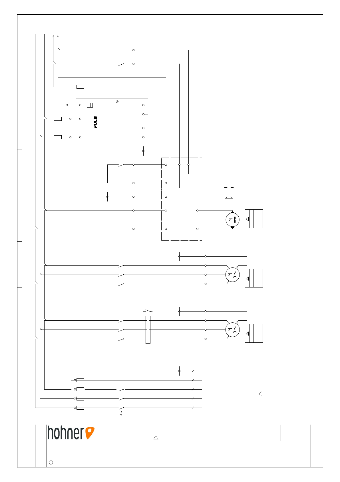
L1L2L3
/2.1
/2.1
L+
L-
13
14
X1 17 18
2.7
K2
F3
2,0A
PE
6
X1 5
F2
T2,0A
230
PE
DC ok
N
AC 11 5/230V
L
-G1
3A,72W
ML70. 100
Uout= 24VDC
Adj. 24-28V
Powe r Supply
63
K2
PE
+
+
-
DC 24 V
-
Steuertrafo
control transformer
transformateur de commande
PE
64
16
2.7
15
PE
14
X1 13
X2:6
X1
X2
L+
X2:5
X1:PE
X1:4
X1:3
A-
L3/N
L1
X1:6
A+
X1:5
L-
Bremse
brake
frein
Y1
2,5 A
0,35kW
A+ A-
M3
180 V/DC
Schiebegestänge
Gleichstrommotor-
direct current motor-
contenu-
sliding rods
tringles coulisse
moteur à courant
A1
5
6
3
4
1
2
2.7
K2
PE
PE
12
11
10
U V W
pe
230 V
0,75 A
0,12kW
Auslagemotor
motor-delivery
M2
moteur-étalage
1 2 3 4 5 6 7 8 9
26.11.08 SC1
Änderun g Name
5
6
3
4
1
2
2.5
K1
4
6
3
2
X1 1
F1
T6,3A
Maschi ne / Machine / Machine
5
4
3
2
1
Q1
20 A
EXACT-PLUS
220/230V 3xAC 50/60HZ
Bennenu ng / Title / Dénomination
Schaltplan - flow diagram -schéma des circuites
C Hohner Maschinenbau GmbH
95
96
2.5
5
6
3
4
1
2
F4
1,75
1-2,9 A
PE
PE
PE
9
8
U V W
X1 7
GNYE
PE
BU
N
GY
L3
BK
L2
BN
L1
Zeichnungs-Nr. / Drawing-Nr. / Dessin-No. Index
pe
230 V
1,75 A
0,37kW
M1
220 / 230 V
3 x AC 50/60Hz
43 40 936
head
piquage
Heftkopfmotor
Netzanschluss
moteur-tête de
motor-stiching-
main supply
au réseau
rattachement
d
Seite
Sheet
Page
1
Page 42
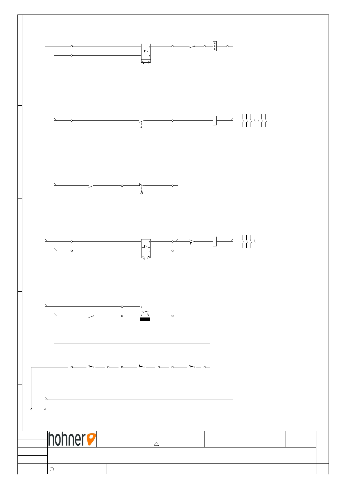
73
74
x1
21
31
BU
GY
WS
BN
+ -
+
39
.7
K2
x2
X1 40
X1 22
H1
Summenzähler
compteur-
adding counter
totalisateur
B3
23
24
X1 30
38
S5
13
14
.5
K1
21
33
22
37
S4
A1
A2
1 2
3 4
5 6
13 14 .3 53 54
63 64 .9 73 74
Heften ein
K2
1.4
1.4
1.4
1.8
1.6
stiching on
piquage marche
top
oben
Heftkopf
stiching head
en haut
tête de piquage
95
96
A1
20
X1 29
BU
GY
BN
WH
+ -
+
36
35
1.3
F4
A2
1 2
3 4
5 6
13 14
K1
.6
1.2
1.3
1.3
Papier
vorhanden
paper existing
papier existant
B2
BU
19
53
54
.7
K2
11
12
X1 23
X1 24
S1
BN
32
X1 25
BK
B1
11
12
S2
34
Heftposition
stiching position
position de piquage
11
12
X1 26
X1 27
X1 28
S3
Sicherheits-
switch
cut-out
schalter
autom.
coupe-circuit
1 2 3 4 5 6 7 8 9
L+
1.9/
19.05.08 SC1
Änderun g Name
L-
1.9/
Maschi ne / Machine / Machine
220/230V 3xAC 50/60HZ
Bennenu ng / Title / Dénomination
Schaltplan - flow diagram -schéma des circuites
C Hohner Maschinenbau GmbH
EXACT-PLUS
Zeichnungs-Nr. / Drawing-Nr. / Dessin-No. Index
43 40 936
d
Seite
Sheet
Page
2
Page 43
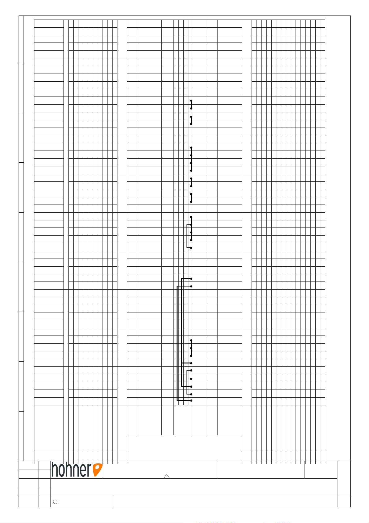
2/9
2/9
2/7
2/6
2/5
2/4
2/3
2/6
2/3
2/9
2/7
2/4
2/2
2/2
2/2
2/2
2/2
2/2
2/9
2/9
2/5
2/3
1/9
1/9
1/6
1/6
1/5
1/5
1/4
1/4
1/4
1/3
1/3
1/3
1/6
1/4
1/3
1/8
1/7
1/2
1/1
1/1
1/1
74K240X1H1
73K239GYB3
A1K23824S5
3722S4
95F436GYB2
35WHB2
34BKB1
14K13321S4
54K232BNB1
13K131
WHBN
3023S5
29BNB2
53K22812S3
2711S3
2612S2
2511S2
2412S1
13K22311S1
22X2H1
21BUB3
20BUB2
A2K219BUB1
-G118L-A1/Y1
14K217L+A1/Y1
64K2166A1
63K2155A1
144A1
133A1
6K212WM2
4K211VM2
2K210UM2
6F49WM1
4F48VM1
2F47UM1
PEPEPEA1
PEPEPEM2 / S5
PEG1PEPEPEPE / M1
230G1F26
0G1F25
F14N
6K1F136Q1
3K1F124Q1
1K1F112Q1
supply
Anschl uß
unité
Gerät
recco rdement
binder name
appli ance
Klemm enname
pont
brigde
Brüc ken
nom de la borne
supply
Anschl uß
recco rdement
numero borne
binder number
Klemm ennummer
1
GY
BU
2
GY
WH
BK
1
B3
4
3
6
5
2
1
3
2
1
3
2
1
YE
GN
YE
GN
YE
GNYEGN
BU
BK
BN
BK
unité
Gerät
appli ance
BN
BN
WH
BN
BN
2
1
2
1
2
1
2
BU
BU
BU
YE
GN
vert/ jaune
blanc
green/Yellow
white
WH = weiß
GNGE = grün/gel b
bleu
gris
blue
gray
BU = blau
GY = g rau
noir
brun
black
brow n
1 2 3 4 5 6 7 8 9
19.05.08 SC1
Änderun g Name
Maschi ne / Machine / Machine
EXACT-PLUS
220/230V 3xAC 50/60HZ
Bennenu ng / Title / Dénomination
Klemmleiste - connector block -réglette de bornes
C Hohner Maschinenbau GmbH
X1
Ziel / dest. / fin.
Q1M1M2A1S1S2S3B1B2S4S5B3H1
123456789
Nr.
Zeichnungs-Nr. / Drawing-Nr. / Dessin-No. Index
101112
43 40 936
BK = schwarz
13
BN = braun
d
Seite
Sheet
Page
3
Page 44
Description
interrupteur principal (interr. dúrgence)
coupe - circuit autom. porte
coupe - circuit autom. couvercle / étalange
coupe - circuit autom. couver de étalage
tôle de protection/étalage
interrupteur f. de course, tête de piquage
commande par pédale
détecteur de proximeté
tringles coulisse
reflet barrage photoélectrique
reflet barrage photoélectrique
convertisseur M3
frein M3
transf. de commande avec redesseur courant
compeur totalisateur (spécial)
fusibles de sécurité-cir. principal T6,3 A
fusibles de sécurité-transformateur
primaire T2,0 A
fusibles de sécurité-commande T2,0 A
Description
main switch (emergency switch)
cut-out, autom. switch door
cut-out, autom. switch prot. cover
delivery
cut-out, autom. switch cover plate/
delivery
micro-switch stiching head
pedal switch
proximity switch-sliding rods
fluidic light barrier
fluidic light barrier
power converter M3
brake M3
control transformer with rectifier
adding counter (special)
saftey fuses-main circuit T6,3 A
saftey fuses-transformer
primary T2,0 A
saftey fuss-electric circuit
contacteur tête de piquage
contacteur moteur-étalage
bloc contact de secours 40DILE
moteur-tête de piquage
moteur-étalage
moteur à courant contenu-tringles coulisse
relais de surchargé
adaptateur
réglette de bornes
control T2,0 A
contactor stiching head
contactor motor-delivery
auxiliary contact-block 40DILE
motor-stiching head
motor-delivery
direct current motor-sliding rods
overload relay
adapter
connector block
Bezeichnung
1 2 3 4 5 6 7 8 9
Bez. Art. Nr.
Pos.
26.11.08 SC1
Änderun g Name
Hauptschalter (Not-Aus)
Sicherheitsschalter Türe
43 00 770
43 00 004
S1
Q1
1.1
2.2
Sicherheitsschalter Abdeckblech/Auslage
Sicherheitsschalter Schutzhaube/Auslage
43 00 004
43 00 004
S2
S3
2.2
2.2
Endschalter Heftkopf
Fußschalter
Näherungsschalter Schiebegestänge
43 00 271
43 00 068
43 00 771
S4
S5
B1
2.6
2.7
2.3
Maschi ne / Machine / Machine
220/230V 3xAC 50/60HZ
Bennenu ng / Title / Dénomination
Ersatzteile - spare parts - pièces de recange
C Hohner Maschinenbau GmbH
Reflexlichtschranke
Reflexlichtschranke
Stromrichter M3
43 00 381
43 00 381
43 00 512
B2
B3
A1
2.4
2.9
1.5
EXACT-PLUS
Bremse M3
Steuertrafo mit Gleichrichter
Summenzähler (Sonder)
Sicherung Hauptstromkreis T6,3 A
Sicherung Trafo primär T2,0 A
Sicherung Steuerstromkreis T2,0 A
43 00 820
43 00 396
43 00 268
43 00 274
43 00 274
F1
F2
Y1
1.6
H1
G1
1.7
2.9
1.1
F3
1.7
1.8
Zeichnungs-Nr. / Drawing-Nr. / Dessin-No. Index
Schütz Heftkopfmotor
Schütz Auslagemotor
Hilfskontaktblock 40DILE
43 00 805
43 00 805
43 00 806
K1
K2
K2
2.5
2.7
2.7
43 40 936
Heftkopfmotor
Auslagemotor
Gleichstrommotor-Schiebegestänge
Motorschutzrelais
Adapter
Klemmleiste
42 00 135
42 00 159
42 00 158
43 00 743
43 00 749
F4
M1
M2
M3
1.3
1.4
1.5
X1
1.3
d
Seite
Sheet
Page
4
 Loading...