

Page 1
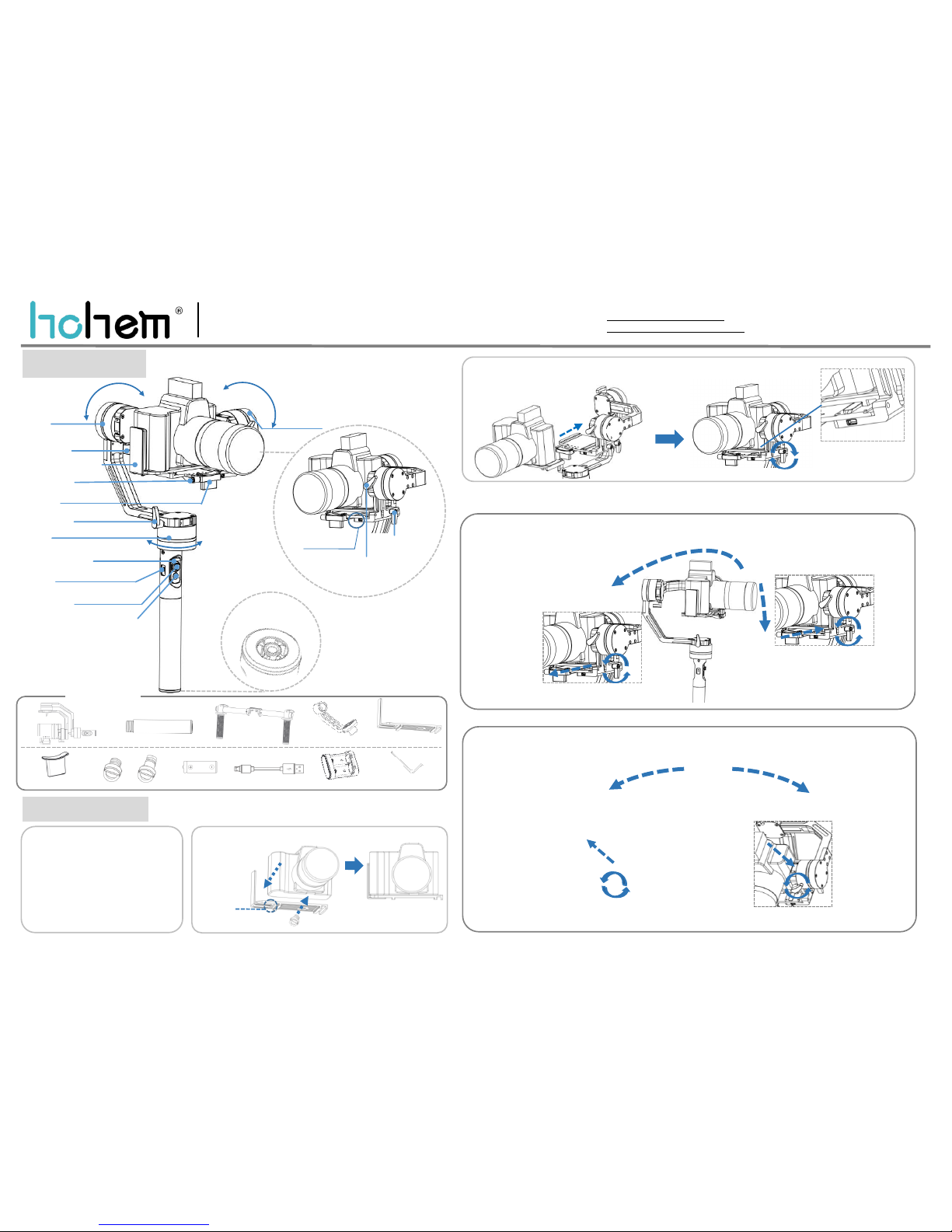
Product Overview
Quick Installation
DG1Quick Start Guide V1.0
3. Balancing:(1)Balancing the Tilt Axis
Roll Axis
L-Shape Mounting Plate
Thumb Screw 1
1.Insert 4PCS
18350 batteries,
ensure battery
positive pole upside
*4 PCS
Tilt Axis
2.Camera Installation:(1)Install Mounting Plate
(2) Place the mounting plate which the camera is mounted
on the clamping plate and tighten the screws
Button up the mounting
plate and clamping plate
via a Z-shape socket
Screwing clockwise to fix the mounting plate
If camera lens tilts downside
If camera lens
tilts upside
a. Adjust tilt axis balance in horizon direction:Placethe gimbal like picture 3-1-a, hold the roll axis and keep
it in horizontal steady, position the camera lens pointing forwards and loosen the lens, observe the camera
status.
If camera lens
tilts backwards
Loosen the thumb screw
4 on tilt axis, move the
camera downwards
through sliding arm until
camera is balanced.
Move the camera backwards
through sliding arm to make
camera lens balanced.
b. Adjust tilt axis balance in vertical direction: Place the gimbal like picture 3-1-b, hold the roll axis and
keep it in horizontal steady,position the camera lens pointing upwards, then loosen the lens, observe
the camera status.
Loosen the thumb
screw 5, move the
camera forwards
through sliding arm
to make camera
balanced
3-1-a
Web:www.hohem-tech.com
E-mail:[email protected]
Tel:0755-86573216 (Copyright: Hohem Technology Co.,Ltd)
Rolling 360°
Tilting 360°
Panning 360°
Len Holder*1 1/4 Inch Screw 18350 Battery*4 USB Cable*2 Battery Changer*2
Single Handle*1
(Please use the standard charger
for charging)
Connecting Arm*1
Accessories List
Gimbal*1
1/4 Inch short screw*1
Thumb Screw 2
Lens Holder
Pan Axis
Signal Indicator Light
1/4”Extension
Screw Hole
Short*1 L ong*1
Allen Wrench*1
Thumb Screw 5
L-Shape
Mounting Plate*1
Thumb Screw 4
3-1-b
Adjust the
screw
making
mounting
plate
appropriate
position.
Ensure the camera
tightly close to
mounting plate margin
If camera lens
tilts forwards
Thumb Screw 3
USB Port
Move the camera
upwards through
sliding arm until
camera is balanced
5-Way Joystick
Multifunctional Button(Power On/ Off)
&
Status Indicator Light
UARTExtendedPort
DUO Handles*1
Page 2
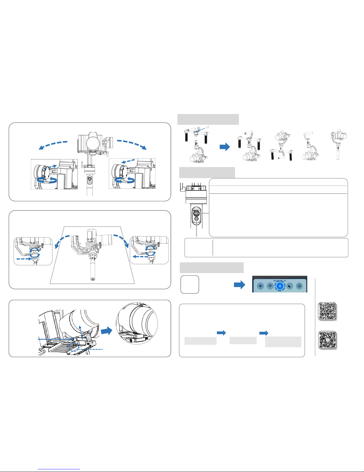
(2)Balancingthe Roll Axis
Loosen the thumb screw
3 on pan axis, move the
camera to right side
until camera is
balanced.
Place the gimbal like picture 3-3, hold the pan axis and stay level balanced, then release the camera,
observe the lens status.
3-2
(3)Balancing the Pan Axis
3-3
Horizontal
If camera flops left
4.Lens Is Fixed By The Lens Holder
After tilt, roll, pan axis balancings done, fix the lens by lens holder.
b.Loosen screw
bolt on the lens
holder, and fix the
lens with
shockproof cotton
strip to the lens
a.To adjust the lens holder position as per
the final lens position.
If camera flops left
Operating Instructions
Multifunctional button(Switch working modes&status indicator light)
Single press:Panning mode following, tilt axis&roll axis both locked, camera can move
to left or right smoothly, indicator light flash for once.
Double press: Panning&Tilting mode following,roll axis locked, camera can move to
left/right, and pitch rotate, indicator light flash for twice.
Triple press: locked mode, all 3 axis locked, the camera stays in its current orientation,
indicator light flash for triple.
Long press for 6 seconds: Enter into initialization calibration mode,status light is normal on.
Power on: Long press for 3 seconds until the status indicator light flash for twice.
Power off: Long press for 3 seconds until the status indicator light flash for twice.
*More controllable functions can be realized by connecting auxiliary device in the UART extended port.
Multi Functional
Button&Status
Indicator Light
5-Way Jostick
UP/DOWN:Adjust tilt angle RIGHT/LEFT: Adjust pan angle
APP Connecting Instruction
(1) Scan the QR code and download APP
“Hohem Gimset” in APP Store or Google Play
(2)Launch the bluetooth on the smartphone
(Support iOS system 8.0 or above and Android system 4.4 or above)
Click the correct model
(3)
Connect the device
Please scan the QR code to get
more functions introduction
Make sure the bluetooth
is connected
Multiple Configurations
By using 1/4 camera long screw to lock the DUO handles
Place the gimbal like picture 3-2, hold the rollaxis and stay level, then loosen the camera, observe
the roll axis status.
If camera flops right
Loosen the thumb screw 1, move the camera to
left side until camera is balanced.
Loosen the thumb screw 1, move the camera to
right side until camera is balanced
If camera flops right
Loosen the thumb screw
3 on pan axis, move the
camera to left side until
camera is balanced.
Please scan the QR code to get
more products enquiries
Underslung mode
Upright mode
Briefcase mode
Vertical hold mode
Page 3

FCC statements:
This device complies with part 15 of the FCC rules. Operation is subject to the
following two conditions: (1) this device may not cause harmful interference, and (2)
this device must accept any interference received, including interference that may
cause undesired operation.
NOTE: The manufacturer is not responsible for any radio or TV interference caused
by unauthorized modifications or changes to this equipment. Such modifications or
changes could void the user’s authority to operate the equipment.
NOTE: This equipment has been tested and found to comply with the limits for a
Class B digital device, pursuant to part 15 of the FCC Rules. These limits are designed
to provide reasonable protection against harmful interference in a residential
installation. This equipment generates uses and can radiate radio frequency energy
and, if not installed and used in accordance with the instructions, may cause harmful
interference to radio communications. However, there is no guarantee that
interference will not occur in a particular installation. If this equipment does cause
harmful interference to radio or television reception, which can be determined by
turning the equipment off and on, the user is encouraged to try to correct the
interference by one or more of the following measures:
‐ Reorient or relocate the receiving antenna.
‐ Increase the separation between the equipment and receiver.
‐ Connect the equipment into an outlet on a circuit different from that to which the
receiver is connected.
‐ Consult the dealer or an experienced radio/TV technician for help.
The device has been evaluated to meet general RF exposure requirement, The device
can be used in portable exposure condition without restriction
Federal Communication Commission (FCC) Radiation Exposure Statement
Power is so low that no RF exposure calculation is needed.
 Loading...