

Page 1
Grow-Flex™ Feed System
1
HS593 Feed Line Control Unit – 230V Single Phase
General Installation Notes:
Make sure that power is disconnected from system prior to servicing.
Installation of this equipment and related OEM equipment should be in accordance with these instructions, OEM’s
installation instructions and local codes (if applicable). Failure to follow specified instructions may cause damage to
equipment and/or personal injury or death.
Take special note of any Warnings or Safety Decals on the equipment and in manuals.
Always wear protective clothing and any applicable Personal Protective Equipment (Safety Glasses and/or Ear
Plugs) when working with the equipment.
Discarded materials, equipment and boxes should be recycled in accordance with local and national codes.
Unless otherwise specified, all Feed Delivery Systems (Diameters) are installed similarly.
Note: Control Unit is to be wired in accordance with all
capacities are to be sized according to applicable electrical code specifications or other regulations.
applicable
Safety Instructions:
Read all safety messages in this manual and on equipment safety decals. Follow recommended precautions an d
safe operating practices.
Ground all electrical equipment for safety.
Ground all non-current carrying metal parts to guard against electrical shock.
Always keep safety decals in good condition and replace missing or damaged decals.
Overview:
The GrowerSELECT HS593 Control Unit is designed for use with a flexible auger feed system where control of an
auger drive motor is required. Power to the auger drive motor is done through feed pressure being applied to a
diaphragm coupled to an electrical switch internal to the control unit housing. This switch is used to control the
auger drive motor by turning off the power when feed is present and turning on the power when feed has been
removed from the control unit housing.
The sensitivity of the electrical switch is not adjustable.
MAXIMUM LOAD RATING: 1 ½ HP @ 230VAC
A red indicator light on the side of the switch housing will illuminate when the diaphragm has been pressed
(MOTOR OFF) and the switch has been activated.
The ON/OFF switch is used to enable or disable the Control Unit. DO NOT USE THIS SWITCH AS
DISCONNECTING MEANS FOR SERVICING.
local and national electrical wiring codes. All wiring sizes and fuse
Page 2
Grow-Flex™ Feed System
2
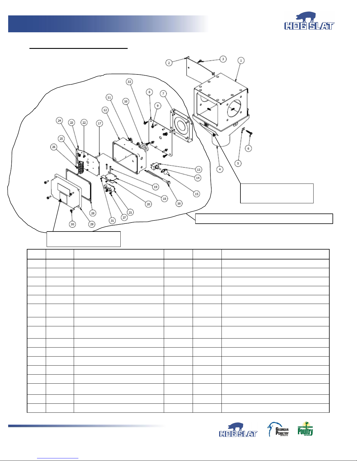
REF # PART #
DESCRIPTION
REF # PART #
DESCRIPTION
1
HS590-1
ASSEMBLY
HOPPER
17
SW
ITCH ACTUATOR PIN
2
HS590-11
ACCESS GATE
18
SW
ITCH MOUNT BRACKET
3
#10-16 X 3/4" HEX SELF DRILLING SCREW
19
#6-32 X 1", PHILLIPS PAN HEAD MACHINE SCREW
4
HS591
DROP CONE - CLARIFIED PLASTIC
20
INSULATING FILM
5
CONTROL UNIT CLAMP
21 EL1052M
SNAP ACTION 20A @ 250V
6
#10-16 X 1" HEX W ASHER SELF DRILLING
SCREW
22
#6-20 X 3/8" TAPPING SCREW TYPE BT
7
HS582
DIAPHRAGM
ASSEMBLY
23
SW
ITCH
ASSEMBLY
COMPONENT MOUNT PLATE
8
SW
ITCH ASSEMBLY MOUNT PLATE
24
#10 X 3/8" THREAD FORMING - GROUNDING
SCREW
9
#10-32 HEX MACHINE NUT
25 EL1072
6
POSIT
ION 18-10 AW G TERMINAL STRIP
10 HS529-45
PLUNGER SEAL
26
#6-32 X 1" PHILLIPS PAN HEAD TAPPING SCREW
11
#10-32 NYLON LOCK NUT
27
#6-32 HEX MACHINE NUT
12
SW
ITCH ASSEMBLY ENCLO SURE
28 HS589-3
GASKET
13 EL1011
TOGGLE SW ITCH, DPST, 20A @ 250V, 2HP
29
SW
ITCH HOUSING COVER
14
LEGEND PLATE, ON/OFF
30
SHOULDER SCREW #10-16 X1.375” HEX W ASHER
HEAD
15 EL1083
TOGGLE SW ITCH BOOT COVER
31
#6-32 X 1/4" SCREW
16 EL1079
INDICATOR LAMP, RED, 250V
32
#10-16 X 3/4" HEX W ASHER SELF DRILLING SCREW
HS593 Feed Line Control Unit
Safety Decal HSLABEL-008
“W warning Shock Hazard”
Safety Decal HSLABEL-035
“Warning Rotating Auger”
HS589 - Switch Assembly Control Unit 230V-Single Phase
Page 3
Grow-Flex™ Feed System
3
Installation:
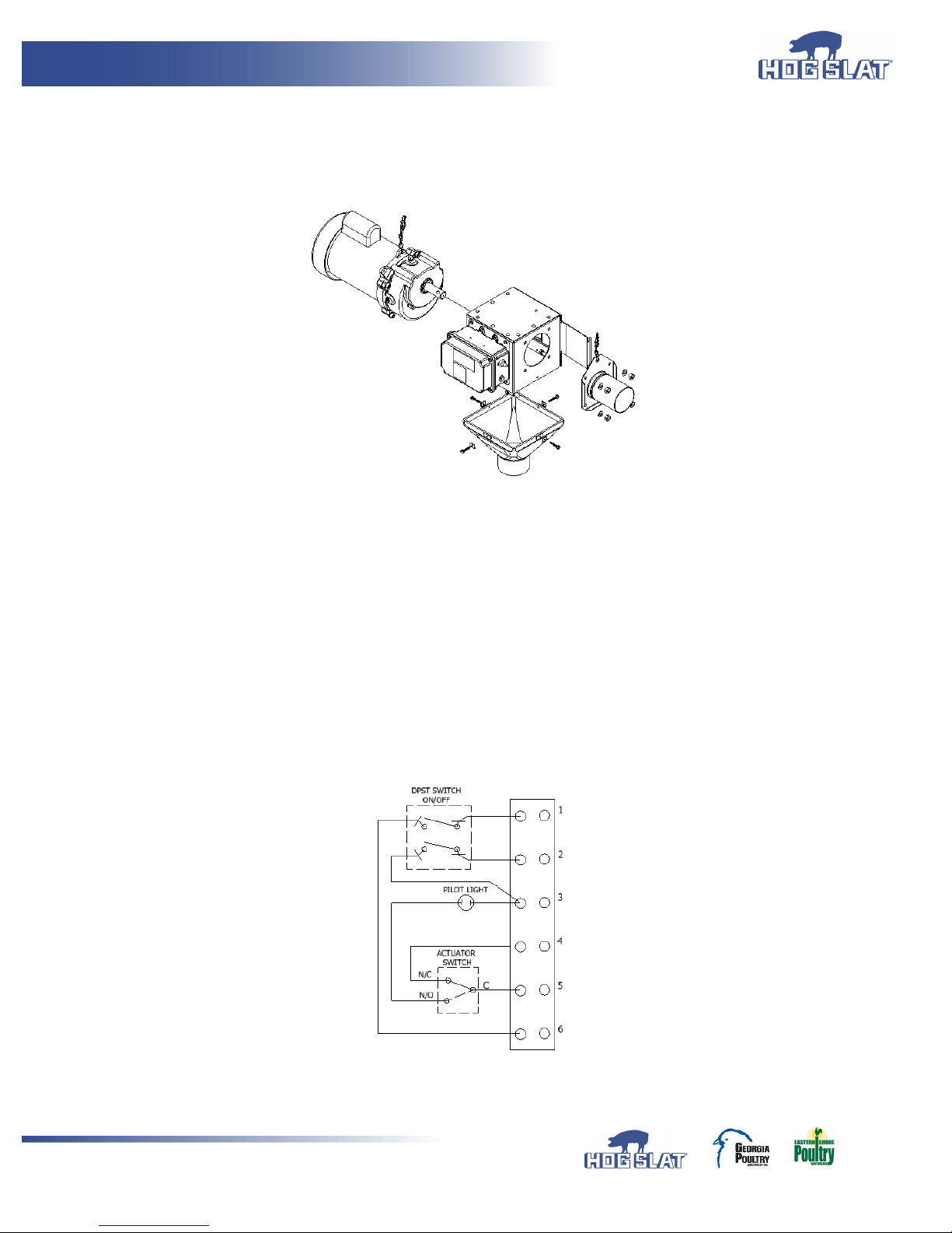
1. (Figure 1) illustrates a typical installation example of the HS593 control unit.
a. Mount tube anchor to one side using (4) 5/16” x ¾” bolts with (4) flat washers.
b. Mount auger power drive unit gear box secured with (4) 5/16” x ¾” bolts and (4) flat washers.
FIGURE 1
2. The HS593 Control Unit must be hardwired. See (Figure 2) for factory wiring diagram.
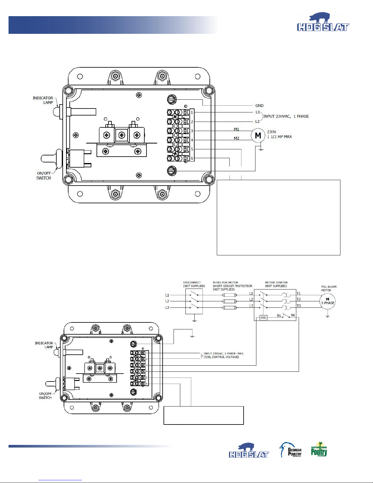
3. See below Figures 3 and 4 for external wiring for single phase and three phase operation.
4. When connecting wire from equipment to terminal strip, remove no more than ¼” of insulation from end of wire.
Be sure there are no stray wire strands before inserting wire into terminal strip. Insert wire into terminal ¼” and
tighten terminal strip set screw.
5. When using Hopper Level Control Switch, switch should be wired as “Normally Closed” contact.
6. If No Hopper Level Control Switch is to be used, Place jumper wire between terminals (5) and (6).
7. Use provided self-tapping screws to provide bonding to Control Unit Switch Assembly and other
connected equipment.
8. Pilot indentions are provided and located to allow for sufficient clearance for ½” non-metallic liquid tight strain relief
cord connectors. DO NOT USE RIGID CONDUIT.
9. Care should be taken when drilling pilot holes to prevent damage to wires or other components.
FIGURE 2
Page 4
Grow-Flex™ Feed System
4
WIRING INSTRUCTIONS FOR SINGLE PHASE – 50/60Hz W/O MOTOR STARTER
FIGURE 3
WIRING INSTRUCTIONS FOR THREE PHASE – 50/60Hz WITH MOTOR STARTER
FIGURE 4
FEED LEVEL SWITCHES
N.C.
HS529
HS597
AP-0094
07051400
14550 CT
6606-0114
HSDTC01
HALO
JUMPER IF NONE USED (16 AW G. W IRE)
REFER TO FIGURE 3 FOR
LEVEL SWITCH
EXAMPLES
CONTACT.
OR
RATED UP TO 1 1/2 HP RATED
Page 5
Grow-Flex™ Feed System
5
REFER TO
FIGURE 3
FOR LEVEL
SWITCH
EXAMPLES
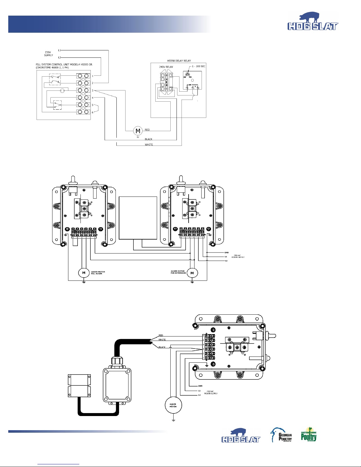
WITH OPTIONAL TIME DELAY
:
WITH EXTENSION GROW-FLEX™ AUGER USING TWO HS593 CONTROL UNITS
CHORE-TIME 46316 DROP TUBE SWITCH
Page 6
Grow-Flex™ Feed System
6
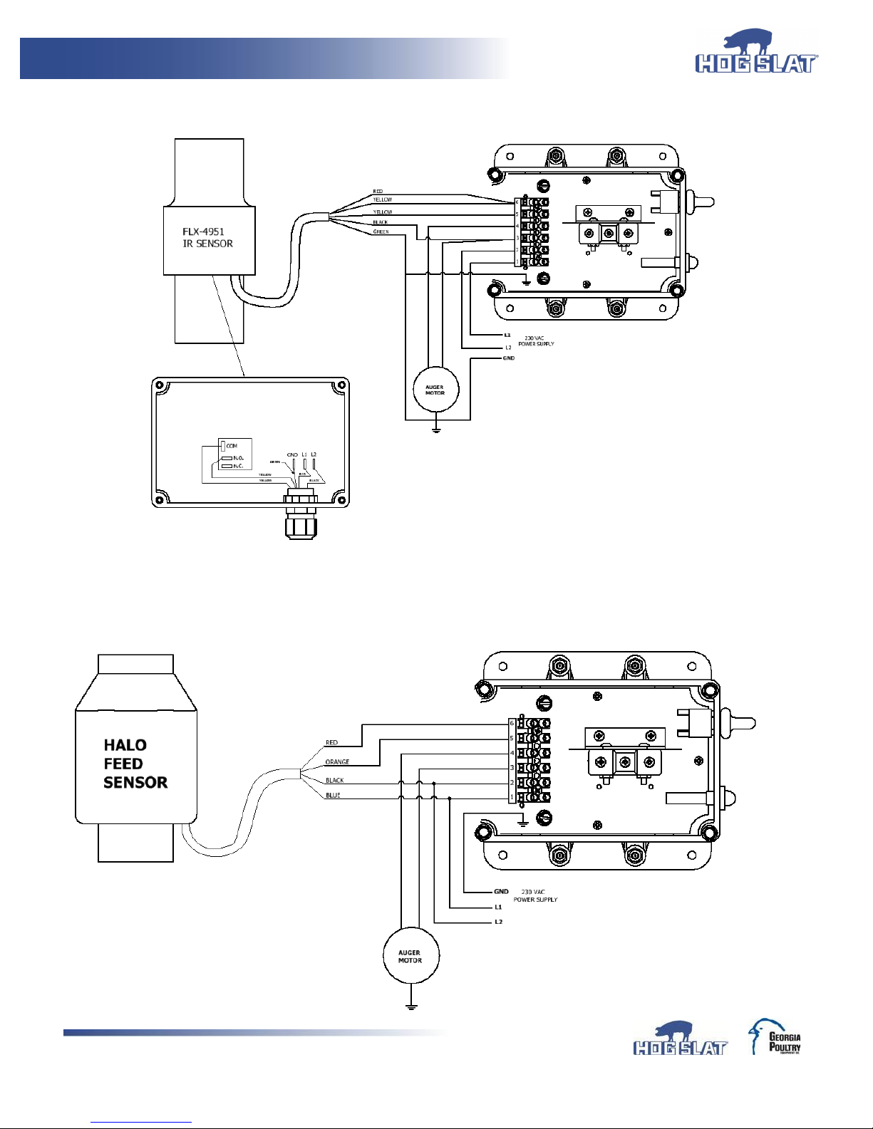
GSI SMART IR ® SENSOR
HALO JR MAX FEED SENSOR
Hog Slat Inc. Newton Grove, NC USA June 2017
Page 7

Grow-Flex™ Feed System
Hog Slat Limited Warranty
Hog Slat warrants products to be free from defects in material or workmanship for a period of
twenty-four (24) months from the date of original purchase. Hog Slat will credit, repair, or
replace, at its option any product deemed defective within this time period. Labor costs associated
with the replacement or repair of the product are not covered by the Seller/Manufacturer.
Conditions and Limitations
1. The product must be installed by and operated in accordance with the instructions published by
the Seller/Manufacturer or Warranty will be void.
2. Warranty is void if all components are not original equipment supplied by the
Seller/Manufacturer.
3. This product must be purchased from and installed by an authorized retailer/distributor
or certified representative thereof or the Warranty will be void.
4. Malfunctions or failure resulting from misuse, abuse, negligence, alteration, accident,
or lack of proper maintenance shall not be considered defects under the Warranty.
5. This Warranty applies only to components/systems for the care of poultry and livestock.
Other applications in industry or commerce are not covered by this Warranty.
6. This Warranty applies only to the Original Purchaser of the product.
The Seller/Manufacturer shall not be liable for any Consequential or Special Damage which
any purchaser may suffer or claim to suffer as a result of any defect in the product.
“Consequential” or “Special Damages” as used herein include, but are not limited to, lost or
damaged products or goods, costs of transportation, lost sales, lost orders, lost income,
increased overhead, labor and incidental costs and operational inefficiencies.
THIS WARRANTY CONSTITUTES THE SELLER/MANUFACTURER’S ENTIRE AND SOLE
WARRANTY AND THIS MANUFACTURER EXPRESSLY DISCLAIMS ANY AND ALL OTHER
WARRANTIES, INCLUDING, BUT NOT LIMITED TO, EXPRESS AND IMPLIED
WARRANTIES AS TO MERCHANTABILITY, FITNESS FOR PARTICULAR PURPOSES
SOLD AND DESCRIPTION OR QUALITY OF THE PRODUCT FURNISHED HEREUNDER.
Hog Slat Retailers/Distributors are not authorized to modify or extend the terms and
conditions of this Warranty in any manner or to offer or grant any other warranties for
GrowerSelect products in addition to those terms expressly stated above. An officer of Hog
Slat must authorize any exceptions to this Warranty in writing. The Seller/Manufacturer
reserves the right to change models and specifications at any time without notice or
obligation to improve previous models.
Hog Slat Inc. Newton Grove, NC USA June 2017
7
Page 8
Grow-Flex™ Feed System
Part Number: HSMANUAL-009
REV A9
Market: Hog & Poultry
This equipment must be installed in accordance with all State
and Local Codes and applicable Regulations which should
be followed in all cases. Authorities having jurisdiction
should be consulted before installations are made.
Hog Slat, Inc.
PO Box 300
Newton Grove, NC 28366
Phone: (910) 594-0219
Fax: (910) 594-1392
www.hogslat.com
Copyright © 2017 by Hog Slat, Inc
Hog Slat Inc. Newton Grove, NC USA June 2017
8
 Loading...