

Hogfors 465, 465KX, 46501KX, 46501, 46501KC Instructions For Installation, Use And Maintenance Manual
...Page 1

SILVER LINE
BALL V-SECTOR VALVE
INSTALLATION AND MAINTENANCE
MANUAL
465 series
20-04-2011
Page 1 of 4
BALL-SECTOR VALVE
465, 46501 SERIES
INSTRUCTIONS FOR INSTALLATION, USE AND
MAINTENANCE
1. Before installation.
Read these instructions carefully before starting the valve installation and start-up work.
During the receiving inspection, check that the valve and its accessories are free from any transportation-
induced damage.
During storage, the valve must be protected from dirt, rain, prolonged sunshine or sub-zero temperatures.
The protecting cap should be removed from the valve ends just before installation
2. Installation.
In outdoor installation, take care to drain the valve, as there is danger of freezing; especially the
space between the ball and valve body.
The valve should not be fitted at the lowest point of the pipework or in over low-level locations.
The pipework should be carefully cleaned before the valve is fitted. Remove any foreign matter that may
have got into the valve during transportation or storing.
Test the proper operation by opening and shutting the valve.
During installation, the ball sector must be close.
When installing the valve in the pipeline, the arrow on the body denotes the correct direction of flow.
After completion of flange welding, make sure that valve will not be under excess load, that flanges are
parallel and coaxial to each other.
After installation, flush out the pipework through.
3. Valve operation.
The ball sector valve is specially design for the controlling pulp and liquid flows.
4. Maintenance.
In normal conditions, these valves do not require maintenance.
Never remove the gland and sub-shaft cover while the valve is pressurised.
Page 2

SILVER LINE
BALL V-SECTOR VALVE
INSTALLATION AND MAINTENANCE
MANUAL
465 series
20-04-2011
Page 2 of 4
The valve must be removed from pipe system and disassembled when performing the following
maintenance operations:
−
Inner cleaning of the valve.
−
Ball seat cleaning/lapping.
−
Bearing replacement.
−
Body joint replacement.
Disassembly
Always empty the valve before disassembling for maintenance operations or before returning it to the
manufacturer for service.
Remove the hand lever or actuator and mounting bracket.
When detaching and installing the actuator, take care not to hit or load the stem, as this will result
in damage to the ball sector.
−
Mark the position of the actuator to the valve.
−
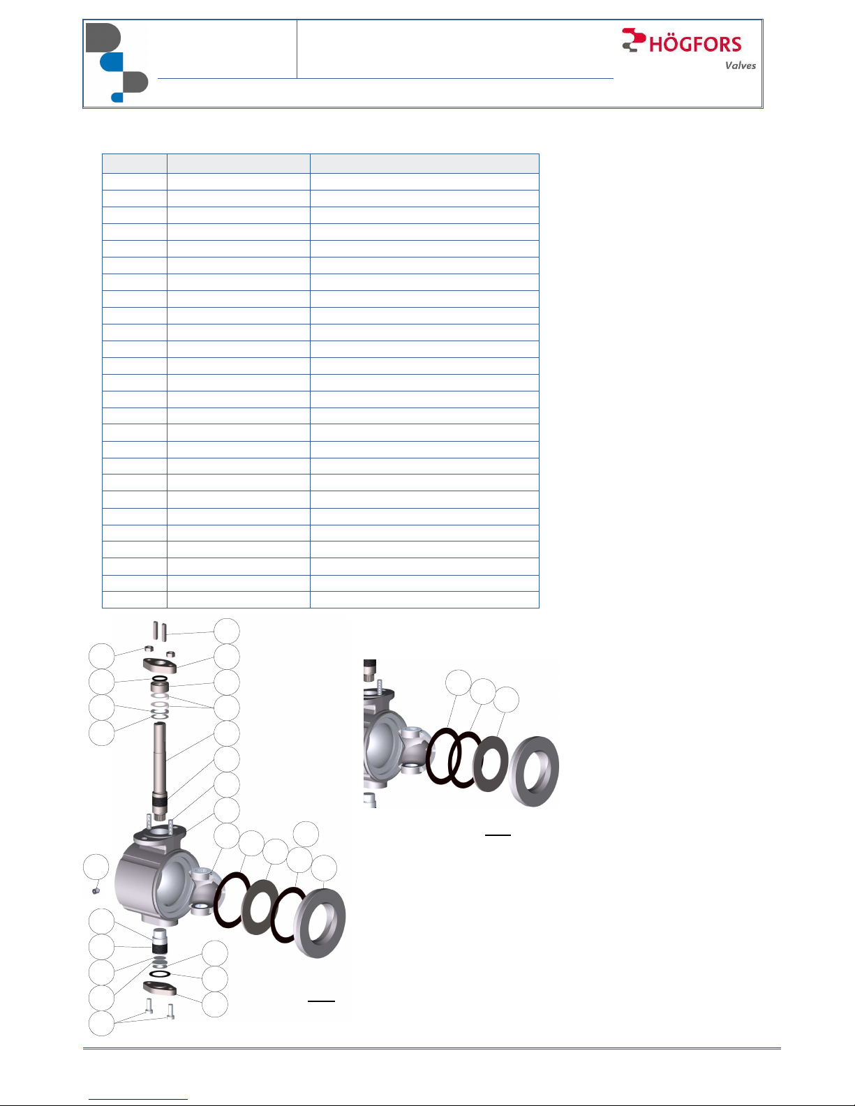
Remove the end piece 2, secured by spot locking from the body 1.
−
For version with lock by kernel: use suitable chisel, and hit on several
spots to loose the end piece (see picture). After removing of end piece,
correct hitting points in body so that the valve can be assembled again.
−
For version with lock screw: unbolt 2 screws and remove the end piece.
−
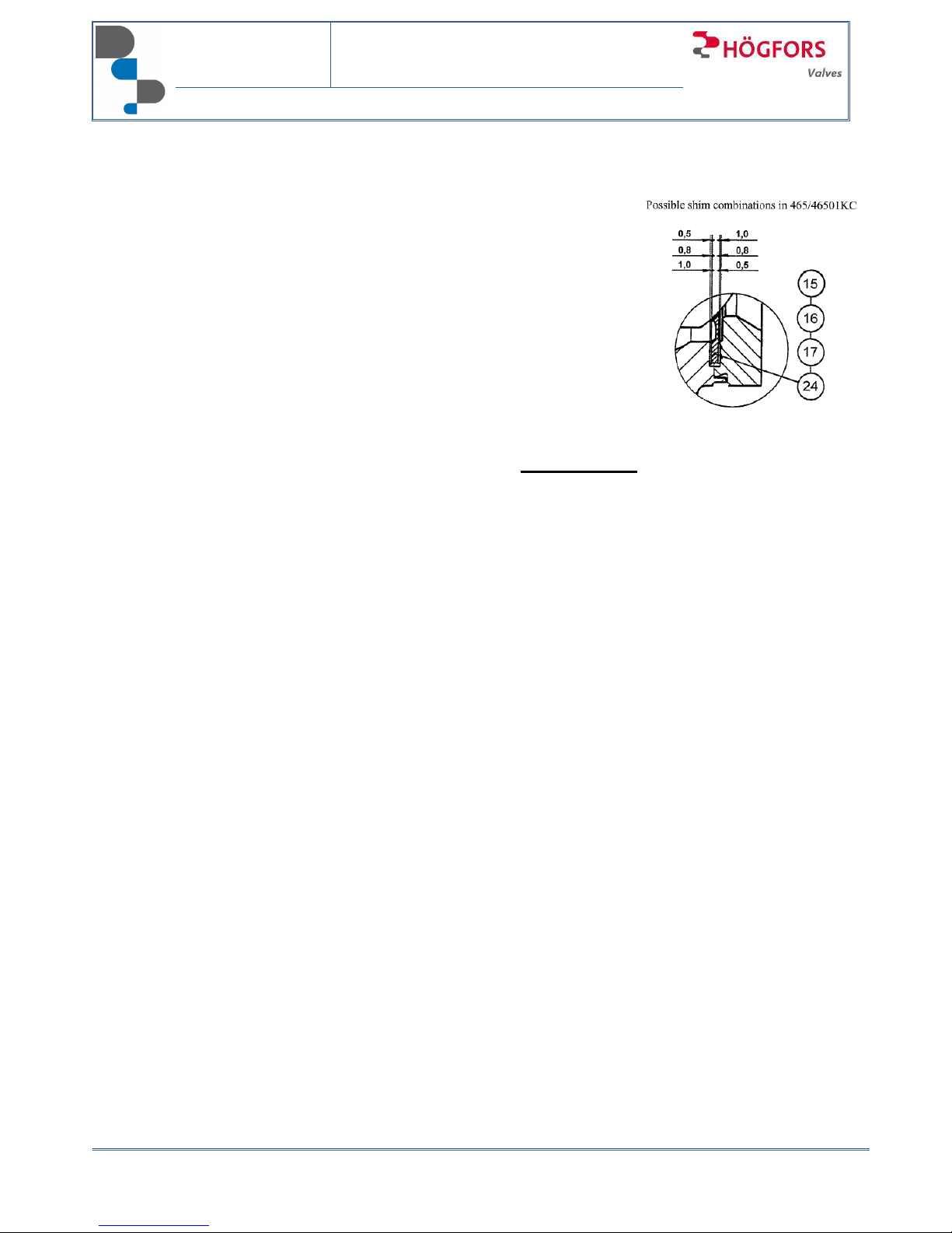
KC: remove shims 15, 16, 17 and seat 24 (actually 2 shims only in use).
−
TC: remove shim 26, support ring 25 and seat 24.
−
Remove hexagonal socket screws 23, sub-shaft cover 8 and sub-shaft cover packing 18.
−
Remove cup spring 14 thrust bearing plate 10, lower thrust bearing 13.
−
Remove nuts 22, gland 6, O-ring 20 and spacer ring 7.
−
Pull out stem 4, and push sub-shaft 5 out through inside of the valve by supporting the ball at the
same time.
−
Remove V-ball 3.
−
Remove (from upper shaft 4) gland packing 19, thrust bearing ring 9, upper thrust bearing 12 and
shaft bearing 11.
Assembling
In assembly, follow the disassembly instructions in reverse order. Note the marking groove when joining
the upper shaft to the ball. Make sure all sliding and sealing surfaces are clean before assembling the
valve.
The Pampus material journal bearing is mounted so that the stainless steel reinforcing net is on the outer
surface.
The installation of the upper shaft bearing can be simplified by using special
bushing (see picture) or by attaching the bearing on the stem with a piece of tape,
which is removed after the stem and bearing have been partly pushed in place.
After assembling the shafts and linked parts, tighten nuts 22 evenly (gland 6) so
that packing is tight. Tighten hexagonal socket screws 23 (sub-shaft cover 8)
evenly. After the tightening, operate the valve several times ensuring smooth
operation.
Page 3
SILVER LINE
BALL V-SECTOR VALVE
INSTALLATION AND MAINTENANCE
MANUAL
465 series
20-04-2011
Page 3 of 4
Set the ball to shut – position.
465KC / 46501KC:
The fit of contact of seat to the ball can be adjusted by the shims (15) and
(16) on the side of the body. Try first 1.0 mm thickness, and if contact to the
ball is not complete, use 0.8 or 0.5 mm thickness. On the side of body
flange, use the remaining shim 15.
Total thickness of body joints must be 1.5mm.
Place end piece 2. Press body and end piece together, and lock by kernel
at 4 points.
Actuator assembly
Check the limit switches. Refer to the actuator installation manual. Execute
pressure test if necessary.
When installing the valve to the pipeline, the ball sector must be closed.
5. Spare part kits
465 / 46501KC:
Shims ..... (0.5, 0.8, 1.0mm) . (15, 16, 17)
Sub-shaft cover packing ...... (18)
Graphite packing.................. (19)
Shaft bearing ....................... (11)
Stellite seat .......................... (24)
Thrust bearings .................... (12, 13)
O-ring .................................. (20)
Order number 465KX__
Order number 46501KX__
465TC:
Shim .................................... (26)
Sub-shaft cover packing ...... (18)
Graphite packing ................. (19)
Shaft bearing ....................... (11)
PTFE seat ........................... (24)
Support ring ......................... (25)
Thrust bearing ..................... (12, 13)
O-ring .................................. (20)
Order number 465TX__
6. Warranty.
The warranty period is stated in the contract.
HÖGFORS OY takes no responsibility for any damage caused by the valve’s incorrect
transportation, handling, installation or use.
The non-leakage warranty exclusively applies to the valves that are provided with a hand gear or an
actuator installed at the manufacturer’s factory, provided that the hand gear or actuator in question
has not been removed or adjusted by the user.
Page 4
SILVER LINE
BALL V-SECTOR VALVE
INSTALLATION AND MAINTENANCE
MANUAL
465 series
20-04-2011
Page 4 of 4
7. Parts list and standard materials
Part Material
1
Body
Stainless steel ASTM A351 CF8M
2
End piece
Stainless steel ASTM A351 CF8M
3
V-ball
Stainless steel ASTM A351 CF8M
4
Stem
Stainless steel 1.4404
5
Subshaft
Stainless steel 1.4404
6
Gland
Stainless steel 1.4404
7
Spacer ring
Stainless steel 1.4404
8
Subshaft cover
Stainless steel 1.4404
9
Thrust bearing ring
Stainless steel 1.4404
10
Thrust bearing plate
Stainless steel 1.4404
11
Shaft bearing
PTFE on stainless steel net
12
Upper thrust bearing
PTFE on stainless steel net
13
Lower thrust bearing
PTFE on stainless steel net
14
Cup spring
Stainless steel 1.4404
15, 16, Shim
Carbon Fibre SFS5811/ Graphite
18
Subshaft cover
Carbon Fibre SFS5811/ Graphite
19
Packing
Graphite
20
O-ring
EPDM
21, 22 Bolt or stud and nut
Stainless steel ISO 3506 A4-80
23
Hexagonal socket
Stainless steel ISO 3506 A4-80
24
T-seat
PTFE
24
K
-seat
Stellite
25
Support ring
Stainless steel 1.4404
26
Shim
Carbon Fibre SFS5811/ Graphite
27
Key
Carbon steel
28
Screw
Stainless steel A4 DIN914
9
12
22
20
24
15
16
3
1
21
11
4
19
7
6
27
2
23
10
8
18
14
13
11
5
24
465TC
465KC
26
25
17
28
 Loading...