

Page 1

geodyna optima
Additional instructions
Wheel balancer
Page 2

Page 3

DISCLAIMER OF WARRANTIES AND LIMITATIONS
OF LIABILITIES
While the authors have taken care in the preparation of
this manual, nothing contained herein:
- modifies or alters in any way the standard terms
and conditions of the purchase, lease or rental
agreement under the terms of which the
equipment to which this manual relates was
acquired,
- increases in any way the liability to the
customer or to third parties.
TO THE READER
While every effort has been made to ensure that the
information contained in this manual is correct, complete
and up-to date, the right to change any part of this
document at any time without prior notice is reserved.
Before installing, maintaining or
operating this unit, please read
this manual carefully, paying extra
attention to the safety warnings
and precautions.
All Information in this manual has been
supplied by the producer of the
equipment:
Snap-on Equipment GmbH
Geschäftsbereich Hofmann Werkstatt-Technik
Postfach 1202
D-64311 Pfungstadt
Tel. +49 6157 12-482
Fax +49 6157 12-484
E-mail: service @hofmann-ge.com
Internet www.hofmann-ge.com
geodyna optima Operator’s Manual
1
Page 4

Contents
1.0 Safety ........................................................................................................................ 6
1.1 Typographic style ....................................................................................................... 6
1.2 Scope of application.................................................................................................. 6
1.3 General safety rules ................................................................................................... 7
1.4 Description of function ............................................................................................... 8
1.4.1 Switching operating modes ....................................................................................... 9
1.4.2 TDI Tread Depth Indication ...................................................................................... 10
1.4.3 Print functions .......................................................................................................... 10
8.0 Layout ..................................................................................................................... 12
9.1 Balancing ................................................................................................................ 10
9.1.1 Wheel measuring run in Optima Mode ..................................................................... 12
9.2 Optima Entry Screen ............................................................................................... 13
9.2.1 Warning Messages in Optima Entry screen.............................................................. 14
9.3 Optima Diagnosis ................................................................................................... 16
9.4 Optima Matching ..................................................................................................... 17
9.4.1 Geometric Matching ................................................................................................ 17
9.4.2 Geometric matching with only the rim ....................................................................... 18
9.5 Rim Only Diagnosis ................................................................................................. 18
9.6 Behind-the-spokes placement ................................................................................. 19
9.7 Advanced Spoke Detection ..................................................................................... 19
9.8 Optima Parameters ................................................................................................. 20
9.9 Print Report ............................................................................................................. 21
10.0 Changing modes of operation ................................................................................. 22
11.0 Optional functions .................................................................................................... 23
11.1 OPTI LINE mode ..................................................................................................... 24
11.1.1 PULL calibration ...................................................................................................... 30
12.0 Error codes ............................................................................................................. 31
13.0 Optimisation / Weight minimisation .......................................................................... 47
14.0 Readjustment by the operator .................................................................................. 47
15.0 Maintenance ............................................................................................................ 48
15.1 Laser scanners seating glass cleaning .................................................................... 48
16.0 Technical data ......................................................................................................... 49
17.0 Accessories ........................................................................................................... 50
17.1 Printer ..................................................................................................................... 50
17.2 Wheel elevator ......................................................................................................... 50
17.3 Trolley for Flanges ................................................................................................... 50
17.4 Perforated flanges for screw stud............................................................................. 50
17.5 SCA Flange............................................................................................................. 50
17.6 Tapered ring ............................................................................................................ 51
17.7 Wheel weight removal tool ....................................................................................... 51
18.0 Printer Installation Instructions (optional) ................................................................... 52
Page 5

1.0 Safety
All safety information relative to the unit is described in
the Safety Manual (fig. 1-1) supplied alongside this
operator’s manual.
The safety precautions must be completely understood
and observed by every operator. We recommend
keeping a copy of the Safety Manual next to the unit
within easy reach of the operator.
This manual contains notes and specific warnings for
dangerous situations that can occur during the
procedures described.
1-1
1.1 Typographic style
This manual contains specific styles of text that
suggest the relative operating modes:
Note: provides a suggestion or an explanation.
WARNING: NON-OBSERVANCE CAN CAUSE
DAMAGES TO THE UNIT OR TO OBJECTS
CONNECTED TO IT.
WARNING: NON-OBSERVANCE CAN CAUSE
INJURY (ALSO SERIOUS) TO THE OPERATOR OR
OTHER PEOPLE.
Dotted list:
• Indicates an action or sequence of actions that the
operator must carry out in the order set out.
1.2 Scope of application
The geodyna 6800 optima balancer is identical to the
geodyna 6800 basic model apart from three laser
scanners for the automatic detection of the wheel data
and the absence of the right detecting arm.
Note: the following additional operating
instructions integrate, but do not replace,
the geodyna 6800 basic manual and the
supplement for wheel balancers with
Power Clamp device, to which reference
must be made for all instructions,
operations, notes and warnings. This
manual refers to them when required.
1
1.2-1
geodyna 6800 optima model (figure 1.2-1)
1 Pedal to operate the Power Clamp and the main
shaft lock.
3
Page 6

Safety & function
1.3 General safety rules
Only properly trained personnel shall be allowed to
operate the geodyna 6800 optima balancer.
The machine must be used exclusively for the scope
of application by following the operating indications
container in the manual.
Unauthorised changes and modifications to the
machine relieve the manufacturer from any liability for
damages and injuries that might result there from.
On no account should safety features be removed or
made inoperative. In general any work on the electrical
1
1.2-1
system, during installation or power supply
modifications, must be carried out by a qualified
electrician in line with relevant national standards and
the regulations of the local power station.
Note: Remove jumper X46 prior to insulation
resistances tests (500 V DC) and high
voltage tests (1000 V AC), in line with EN
60204-1 (see electrical diagram).
It should be noted that working with technical
equipment may always involve an unforeseeable
acceptable risk. Therefore the operator should
eliminate such dangers by operating the machine with
care.
The following points should be observed:
use the machine only as a technical work tool for its
specified scope of application only;
always use original accessories, approved by the
manufacturer, in perfect condition and suitable for the
type of work to be carried out;
follow the instructions, notes and technical data of the
machine manufacturer and the manufacturer of the
wheels to be balanced;
wear suitable protective clothing and accessories (e.g.
goggles, safety shoes, etc.);
avoid eye contact with the laser scanners;
do not knock or camper the laser scanners;
carry out a regular cleaning of the laser scanners
glass;
do not rest on the wheel guard whilst the laser scanner
is in operation.
In case of calibration defects there is an internal
diagnostic that prompts contacting service.
geodyna optima Operator’s Manual
4
Page 7

1.4 Description of function
The wheel data detection is carried out automatically
and with no contact by 3 laser scanners, with
integrated CCD. The 6800 optima balancer calculates
the co-ordinates of the optimal positions for the
application of balancing counter-weights.
The geodyna 6800 optima balancer can be used to
determine geometric information relative to rim
deformations (deviations of the axis in respect of its
rotation axis, commonly referred to as RUNOUT); to
determine geometric information relative to tire
deformations (deviations of the axis in respect of its
rotation axis). This information is useful for an accurate
diagnosis of the wheel behaviour as well as providing
the operator with useful indications to minimise the
effects of these deformations.
The geodyna 6800 optima balancer is able to
automatically determine the unbalance of the rim or
of the wheel in respect of its rotation centre. At the
end of the measuring run the control software carries
out a matching, that consists in corresponding the top
part of the tire with the bottom part of the rim. The
balancer analyses the overall state of the wheel and
prompts for any repairs required.
1.4-1
The geodyna 6800 optima balancer carries out two
types of runout:
1) radial (on the radius);
2) lateral (on the lateral shift).
The geodyna optima balancer also has the TDI (Tread
Depth Indication) system, which provides a general
indication of tread wear. This function is only active in
OPTIMA mode.
The geodyna 6800 optima balancer can operate in
three distinct modes:
a) MANUAL
b) PROFILING
c) OPTIMA
MANUAL
The machine guarantees the basic functions,
suggesting the position and value of the weights to
apply to the rim. The use is similar to the standard
models; balancers fitted only with the left detecting
device. The MANUAL mode is activated through the
functions menu.
PROFILING
This mode is identifiable on the monitor with the symbol
displayed in fig. 1.4-1 detail 1. The control software
automatically acquires the wheel dimensions during
the measuring run. During the normal measurement
cycle the laser scanner automatically sample the rim
shape (internal and external). The machine optically
5
Page 8

Safety & function
suggests the exact application point of the weight on
the rim through the laser beam (laser pointer).
LASER POINTER: even if inactive, the
Laser Pointer function is present on the
optima balancer. The machine is set in
geodata arm mode as default. The Laser
Pointer mode can be activated by
contacting service. For the use of the
geodata arm refer to the instructions
contained in the geodyna 6800 basic
manual.
OPTIMA
Identifiable on the monitor with the symbol displayed
in fig. 1.4-2 detail 1. In this mode the balancer, as well
as the profiling, carries out the automatic diagnosis
of the runout and the reading for the TDI function.
1.4-2
1.4-3
Control of the rim only: in OPTIMA mode, clamping
only the rim on the balancer, the laser scanner detects
the absence of the tire. In this condition, the rear laser
analyses the runout on the bead recess in the internal
part of the rim and will prompt to automatically proceed
with the matching.
1.4.1 Switching operating modes
(fig. 1.4-3)
The balancer can be set so that it presents the desired
mode of operation at power-on.
• Set the desired value in the functions menu:
0 - MANUAL;
1 - PROFILING;
2 - OPTIMA.
Keep the F6 key pressed to switch from Profiling to
Optima and vice versa.
Note: refer to the geodyna 6800 basic manual
for the navigation procedure through the
function menus and personal data entry
modalities.
geodyna optima Operator’s Manual
6
Page 9

1.4.2 TDI Tread Depth Indication
When run in OPTIMA mode, the machine always
automatically detects the depth of the tread groove at
the centre of the tire and over its whole circumference.
According to the mean value detected and the limit
a
b c
1.4.2-1
value set, the program displays one of the following
Tread Groove indications on screen (Fig. 1.4.2-1):
a) GREEN icon = higher than limit set.
b) YELLOW icon = close to limit.
c) RED icon = below limit set.
Note: The information provided for the operator is
intended as a guideline only. The TDI
function is designed to alert the operator
to the need for a closer examination of
wear on the tread.
The operator can set the tread depth limit value for which
wear information will appear on screen. To change the
limit value go to the “Optima Operating Parameters”
menu (Section 9.7).
1.4.3 Print functions
The FUNCTION screen page includes three print settings
items:
Printing. Field for switching the printer On/Off. Set to
On to enable printing. Set to Off to disable printing.
Paper size. Field for selecting the print format. Activate
the format which matches the paper size used, A4 or
Letter.
Printer type. Field for selecting the type of connection
to the machine PC.
- 0 activates the connection via parallel port.
- 1 activates the connection via USB port.
- 2 sets the machine up for a special connection,
reserved for technicians.
7
Page 10

Installation & operation
2.0 Installation
See geodyna 6800 basic model instructions.
3.0 Electrical connection
See geodyna 6800 basic model instructions.
4.0 Controls and displays
See geodyna 6800 basic model instructions.
5.0 Starting the machine
See geodyna 6800 basic model instructions.
6.0 Clamping the wheel
See geodyna 6800 basic model instructions and the
supplement for wheel balancers with Power Clamp
device.
7.0 Entry of wheel type,
balancing mode and wheel size
In Profiling and Optima mode the wheel data entry is
automatic (see later instructions).
For Manual mode functioning see geodyna 6800 basic
model instructions.
geodyna optima Operator’s Manual
8
Page 11

8.0 Layout
The geodyna optima balancer is fitted with a laser
scanner (fig. 8-1, details 1, 2 and 3) for the automatic
measurement of the wheel data.
The internal laser scanner (detail 1) carries out the
following measurements:
a) detects the internal profile of the rim to identify the
optimum position of the weight to apply on the left
part or internal part of the rim;
b) calculates the distance and diameter of the rim;
c) detects the left outer radial and lateral runout;
d) detects the number and position of any spokes.
The laser scanner integrated on the wheel protection
2
1
8-1
3
guard (detail 2), carries out the following
measurements:
a) automatically calculates the best point for the
application of the weight on the external part of the
rim;
b) detects the right lateral and radial runout;
c) detects the width of the rim.
The rear laser scanner (detail 3) carries out the
following measurements:
a) detects the tread runout, or the runout of only the
rim on the bead recess.
9
Page 12

9.1-1
Operational Selections
9.0 Optima BALANCING
The geodyna optima balancer is fitted with 3 laser
scanners with integrated CCD that guarantee an
accurate detection of the characteristics of any type of
wheel. The laser scanners carry out a series of
geometric measurements on the rim, the tread, the
flange and the profile of the rim and of the whole wheel
with a single measuring run of a few seconds. The
measurements detected are then interpreted by the
integrated pc that provides detailed comparative
evidence with a geometric comparison aimed at
improving the wheel efficiency and can print an
exhaustive diagnostic report.
Note: the following instructions describe the
specific functions of the geodyna 6800
optima wheel balancer in OPTIMA mode.
For operations different from the ones
described refer to the manual for the
geodyna 6800 basic model.
9.1-1a
F1 F1
9.1-2 9.1-3
9.1-4
9.1 Balancing
The balancer displays the start screen at power-on (see
geodyna 6800 basic model generic instructions).
The screen in fig. 9.1-1 appears automatically on the
monitor after clamping the wheel or by pressing F4
from the start screen. Keep the F6 key pressed to
select the Optima or the Profiling mode (fig. 9.1-4).
Note: If the Laser Pointer mode was activated
instead of the geodata system, the
balancing screen page appears as
shown in fig. 9.1-1a.
Note: With the Laser Pointer mode switched on,
the image is a true representation of the
actual location of the adhesive weights.
A larger rim cross-section shows the
weights suggested (yellow) or possible
alternatives (grey) in the 6 o-clock zone,
precisely where the laser beam indicates
they should be applied.
F1: to access the rim nominal dimensions screen.
With ALU mode selected, when the geodata arm is
removed, key F1 changes icon (fig. 9.1-2), allowing
relocation of the weight in a different position to the
one suggested.
In contrast, with Laser Pointer mode active the key
appears split in two (fig. 9.1-3): hold down the lower
part of the key and turn the wheel manually to vary the
position of the weight indicated by the pointer. In both
cases, changing the position varies the value of the
weight. Changing position is possible on both wheel
planes. When you change the position of the weight on
one side of the wheel the value of the weight on the
opposite plane turns red to indicate the change of value
and/or angular position.
10
geodyna optima Operator’s Manual
Page 13

9.1-5
Note: The change in the position of the weight
is saved by the machine, then
automatically suggested for all subsequent
wheels with the same dimensions. The
selection is deleted when the machine is
switched off.
F2: the top part of the key is described in the geodyna
6800 basic model instructions. The bottom part of the
key changes the weights application mode. The
normal mode is accessed by pressing the key for
longer (clip balance weights).
F2
F3
F4
Note: The possible application of the weights in
ways other than that suggested by the
machine is indicated by the grey weights
in the positions compatible with the rim
configuration detected.
Note: The change in the weight application mode
is then automatically suggested for all
wheels with the same dimensions, until
the machine is switched off.
F3: The upper part of the key is described in the geodyna
6800 basic model manual.
Use the lower part of the key to select the Vehicle Type
to be operated on. There are three vehicle types
selectable (fig. 9.1-5): CAR, SUV, TRUCK, with runout
limits suitable for the class of vehicle set for each. The
limit values assigned separately to each Vehicle Type
are:
- First harmonic Wheel radial Runout,
- Peak to Peak Wheel radial Runout and
- Tread Depth.
The values can be changed individually and saved by
the user in the "OPTIMA PARAMETERS" menu.
9.1-6
F5
F5
9.1-7
F4: prints the diagnostic report (the printer must be
active). Pressed again it interrupts the current print (in
this case the key will be blocked).
F5: activates the mode on the spokes. For a correct
detection the spokes on the rim must be equidistant,
of a regular shape and of a minimum number of 3
and maximum number of 12. If the number of spokes
has been detected correctly, a check mark will appear
on the relative key (fig. 9.1-6). If the spokes cannot be
detected, the pictorial as shown in Fig 9.1-7 is displayed.
Pressing F5 will display the values of the two separate
weights to apply on the wheel. Therefore it will not be
necessary to introduce the reference spoke location
data as it has already been detected by the control
software. Proceed directly with the application of the
wheel weights. To exit the Spoke mode, press F5 once
again or remove the wheel.
11
Page 14

F6
Operational Selections
If the laser scanners have not been able to detect the
spokes or estimate their location, even if the type of
wheel has been correctly identified, activate the
Advanced Spoke Detection function (Section 10.1) in
the OPTIMA PARAMETERS screen and repeat the
wheel run. In any event, the data with the number of
spokes and their position can be nevertheless
introduced manually
Proceed as follows:
• Keep F5 pressed and contemporaneously manually
rotate the wheel.
• Release F5 when the correct number of spokes is
displayed on the monitor.
• Manually rotate the wheel in order to align one of the
spokes at 12 o’clock.
• Press F5, the control software carries out the
calculation and displays the two weight values,
appropriately divided.
• Fit the weights to the wheel, behind the spokes, as
shown on the monitor.
F6: keeping it pressed changes the mode from Profiling
to Optima. Pressed briefly it accesses the OPTIMA
ENTRY Screen.
9.1.1 Wheel measuring run in
OPTIMA Mode
• Lower the covering guard. If the automatic measuring
run function has not been activated, press the
START key: the balancer carries out the wheel
measuring run piloted by the laser scanners. They
detect the rim profile; measure the wheel runout;
the internal rim lateral and radial and the external
rim lateral and radial.
At the end of the wheel measuring run the balancer
displays any unbalance on the wheel and signals the
points to fit the weights, unless the RUNOUT limits
have not been exceeded, in this case the balancer
automatically suggests the OPTIMA ENTRY procedure.
Press F1 to display the wheel (rim + tire) size data
detected with the wheel measuring run.
12
Press F2 to alternate the characteristics of the weights
(ALU or adhesive): the balancer will automatically
recalculate the value and position of the corresponding
weights.
The wheel measuring run may have detected the
number of spokes: in this case press F5 to determine
the position of the hidden weights.
geodyna optima Operator’s Manual
Page 15

gh
9.2 OPTIMA ENTRY Screen
(fig. 9.2-0)
Press F6 in the balancing screen to access.
The control software automatically displays this screen
a
b
c
e
f
whenever, at the end of the wheel measuring run, the
i
measuring values exceed the preset limits.
d
The overall wheel (rim + tire) measuring run is displayed.
To move the cursor on the wheel graph, rotate the wheel
k
by hand in both directions.
All of the OPTIMA ENTRY screens show the first
harmonic Peak index (1, fig. 9.2-1), which facilitates
advanced diagnosis of the rim or the wheel.
The unbalance data is shown under the graph (first runout
9.2-0
harmonic).
The automatic Position Brake fitted on the machine will
be activated when the peak position is manually brought
to the 12 o'clock point.
The Position Brake function can be temporarily disabled
in two ways:
- In the BALANCING or OPTIMA ENTRY screens press
the STOP key once to disable, press it a second time
to re-enable the function.
- The brake is not activated if the "Rim Cleaning Position
Brake Control" function has been activated in the
FUNCTIONS menu.
1
9.2-1
a) Wheel radial runout.
b) Rim radial runout (if measured).
c) Rim lateral runout (if measured).
d) Runout proportion due to rim or tire.
e) Equivalent static unbalance estimate given by the
runout at 100 km/h.
f) Describes the performance improvement if the
geometric matching is applied.
g) Runout value at the position the graph cursor is
in, which corresponds to the wheel at 12 o’clock.
h) Peak to peak (p-p) graph; the peak to peak value
is the difference between the maximum and
minimum value.
i) Preset threshold on the wheel runout.
k) Warning of defective rim and/or tire. The software
prompts the operator to check for rim or tire
defects, suggesting matching or automatically
showing the screen for the appropriate corrective
action, where necessary.
If defects are found, box “j” may display from one to
9.2-2
three Warning Messages (Section 9.2.1). Each
message may indicate two levels of seriousness,
as follows:
For measurements above the limit value, a Problem
indication is displayed.
For measurements straddling the limit value, the
Possible Problem indication is displayed.
13
Page 16

9.2-2
Operational Selections
If no problems are found with the wheel, tire or rim,
the OPTIMA ENTRY screen page shows “OK” (Fig.
9.2-2).
The appearance of the messages is linked to the limit
values set, which the operator can change using the
OPTIMA PARAMETERS menu (Section 9.6).
(fig. 9.2-3)
F1: restarts an interrupted matching procedure.
F2: displays the screen for the advanced rim diagnosis
(see “OPTIMA DIAGNOSIS” section).
F3: access the preset work parameters in Optima mode
(see “OPTIMA PARAMETERS” section).
F4: print (if printer is available) or interrupts the current
print (in this case the key is blocked).
F5: opens the "OPTIMA MATCHING" screen.
F1 F2 F3 F4 F5
9.2-3
9.2.1-1 9.2.1-2
9.2.1 Warning Messages in
OPTIMA ENTRY screen
Wheel assembly problems messages appear when:
1) wheel peak-to-peak runout is high
or
2) wheel 1-harmonic runout is high and the
proportion of runout between rim and tire is
close to 50 per cent.
Alert Message (Fig. 9.2.1-1):
If no matching is recommended:
High runout on wheel, but no possibility of improving by
matching. Check rim and tire for defects.
If matching is recommended:
High runout on wheel. Geometric matching is
recommended.
Warning Message (Fig. 9.2.1-2):
Possible issue with wheel, but no possibility of improving
by matching. Check rim and tire for defects.
If matching is recommended:
Potential problem on the wheel. Check rim and tire for
defects.
14
geodyna optima Operator’s Manual
Page 17

Rim problems messages appear when:
1) rim radial runout is high
or
2) rim lateral runout is high
or
3) wheel 1-harmonic runout is high and the
proportion of runout between rim and tire is
greater than 60 per cent (high rim 1-harmonic
runout).
Alert Message
If no matching is recommended:
High runout on rim, but no possibility of improving by
matching. Check rim for defects.
If matching is recommended:
High runout on rim. Geometric matching is
recommended.
Warning Message
Possible issue with rim, but no possibility of improving
by matching. Check rim for defects.
If matching is recommended:
Potential problem on the rim. Check rim for defects.
Tire problems messages appear when:
1) wheel 1-harmonic runout is high and the
proportion of runout between rim and tire is
less then 40 per cent (low rim 1-harmonic
runout)
Alert Message
If no matching is recommended:
High runout on tire, but no possibility of improving by
matching. Check tire for defects.
If matching recommended:
High runout on tire. Geometric matching is
recommended.
Warning Message
Possible issue with tire, but no possibility of improving
by matching. Check tire for defects.
If matching is recommended:
Potential problem on the tire. Check tire for defects.
The last line of the warning box is:
Press HELP for more information. Press ESC to return
to balancing screen.
15
Page 18

Operational Selections
9.3 Optima Diagnosis
Advanced diagnostics data
(fig. 9.3-1)
The top graph shows the wheel runout. The lower graph
shows the rim radial runout.
F3: to change from this screen to the following one (see
“Rim radial and lateral runout” section).
Rim radial and lateral runout
(fig. 9.3-2)
The screen page shows the rim radial and lateral runout
graphs.
9.3-1
9.3-2
F3: to change from this screen to the previous one.
16
geodyna optima Operator’s Manual
Page 19

9.4 OPTIMA MATCHING
There are two ways to access the Matching procedure:
1) Manually,
• Press F5 in the "OPTIMA ENTRY" screen (fig. 9.4-1)
to go to the "Optima Matching" screen (fig. 9.4-2).
• From "OPTIMA MATCHING" continue by pressing
- F2 Continues the interrupted Matching.
- F5 Matching from complete wheel.
- F6 Matching from rim only.
9.4-1
9.4-2
9.4.1-1
2) Automatically,
by observing the following conditions:
• RIM ONLY function OFF ("0" for RIM ONLY item in
"OPTIMA PARAMETER" screen).
• Perform the rim only run.
9.4.1 Geometric Matching
(fig. 9.4-2)
At the end of the wheel measuring run the balancer
may prompt carrying out a geometric matching (F5 key
highlighted in the “Optima Matching” screen), whose
diagnosis can provide a substantial improvement to the
wheel performance. To start the geometric matching
procedure proceed as follows:
• Press F5 on the “Optima Matching” screen to start
the procedure. The control software prompts to position
the wheel valve at 12 o’clock (fig. 9.4.1-1).
• Press F6 to confirm the operation.
• Mark the tire in the position suggested by the control
software (fig. 9.4.1-2) and press F6 to confirm. The
control software suggests moving the tire to the tire
changer in order to align the mark on the tire with the
wheel valve (fig. 9.4.1-3).
• After the tire changer, clamp the wheel on the balancer
and confirm with F6. The control software prompts to
carry out a checking cycle. (Press F4 to carry out a
checking cycle of the runout directly).
• Lower the wheel guard and press START: the
balancer will start the checking cycle.
9.4.1-2
9.4.1-3
At the end of the checking cycle the control software
will suggest the new value of the weights and their
location on the rim.
During the geometric matching procedure you can
return step by step to the previous screens by pressing
F5. Pressing F1 displays the balancing screen; press
the ESC or STOP keys to return to the “Optima
Matching” screen; from this last press F1 to continue
the previously interrupted geometric matching
procedure.
17
Page 20
9.4.2-1
9.4.2-0
9.4.2-2
Operational Selections
9.4.2 Geometric matching with
only the rim
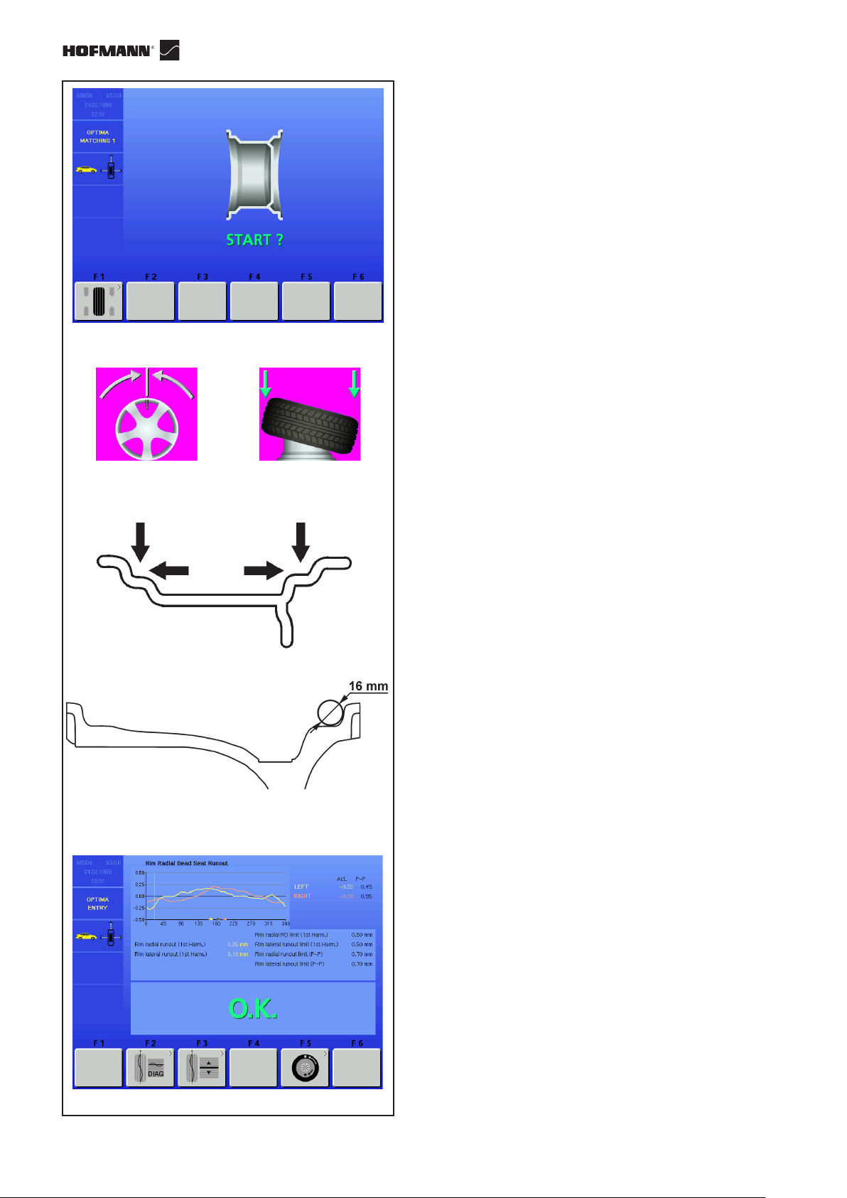
(fig. 9.4.2-0)
• After having clamped the rim to analyse on the balancer,
press F6 on the “OPTIMA MATCHING” screen.
• Lower the wheel guard and press the START key: the
laser scanners carry out the runout measurement in
the bead seats. At the end of the measurement the
control software prompts the alignment of the rim valve
at 12 o’clock (fig. 9.4.2-1).
• Press F6 to confirm.
• Release the rim and move it to the tire changer to fit
the tire (fig. 9.4.2-2).
• After the tire changer, clamp the wheel (rim + tire) on
the balancer and confirm with F6.
• Lower the wheel guard and press START: the balancer
will proceed with the runout calculation with the tire
fitted.
To carry out the geometric matching of the complete
wheel proceed as indicated in the “Geometric
matching” section.
9.5-1
9.5-2
9.5 Rim Only Diagnosis
Optima can be used to perform an analysis of the rim
only and to process its structural parameters,
independently of the tire.
If only the rim is clamped, the machine always
automatically recognises the presence of a rim without
the tire.
To activate the "Rim only diagnosis" function:
• enable "1" in the "Optima Parameters" screen at the
"RIM ONLY" item (m, Section 9.6).
• start the run.
During the run measurements are taken on the lateral
internal profiles and on the bead recesses (fig. 9.5-1).
The laser reading positions on the rim are the same as
the contact points obtained with a circle with 16mm
diameter, as shown in figure 9.5-2.
When the run is complete, the graph showing the curves
for the radial Run-out of the right and left bead recesses
appears (fig. 9.5-3).
Only in the RIM ONLY function, the graph shows three
different coloured markers, indicating the first harmonic
peak position for:
Left bead recess - Yellow triangle
Right bead recess - Red triangle
Mean of the entire rim - Grey triangle
When the rim is turned, it will be stopped by the brake
in each peak position, to facilitate rim marking. The
18
9.5-3
geodyna optima Operator’s Manual
Page 21
9.5-4
peak markings on the rim can then be suitably combined
with the minimum reference present on the tyre.
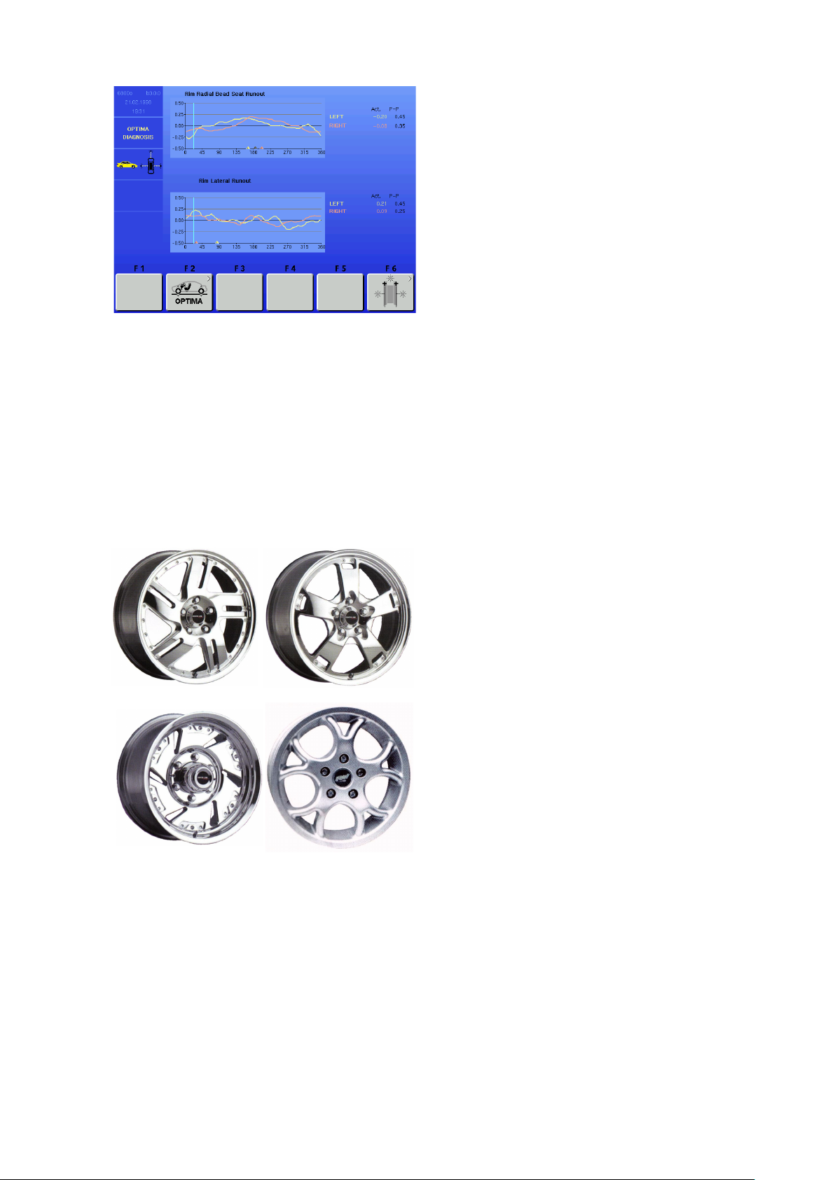
• press F2 for further information about the rim Runout
(Fig. 9.5-4).
These graphs also show the first harmonic peak
markers, combined with the Position Brake.
The "RIM ONLY" diagnosis uses specific limit values,
irrespective of those used for the whole wheel. The
factory values set are:
First harmonic Radial/Lateral Runout = 0.5
Peak to Peak Radial/Lateral Runout = 0.7.
The values can be changed by the user in the "OPTIMA
PARAMETERS" menu.
Note: Activating the "RIM ONLY" function also
allows a specific printed report to be
obtained (if optional printer is present) for
the rim only "Rim diagnostic report" (see
Section 9.7).
Note: The function lengthens the measuring
cycle to a total of 55 seconds.
9.7-1
9.6 Behind-the-spokes
placement
See geodyna 6800 basic model instructions and F5
key description in section 9.1.
9.7 Advanced Spoke Detection
This mode, which can be activated when required, allows
absolute precision when detecting the position and
dimensions of the rim spokes, to allow more precise
behind the spokes placement. If the laser scanners can't
recognise the spokes or the operator decides he is
dealing with a rim with a particularly complex shape,
enable the Advanced Spoke Detection function which
recognises any type of spokes, even those with unusual
19
Page 22
Operational Selections
shapes, for example: paired, oblique, with holes or of
different sizes to one another (fig. 10.1-1).
a
b
c
d
e
f
g
h
i
k
m
n
Before performing the measuring run:
• From the OPTIMA PARAMETERS screen select 1
next to the "Advanced Spoke Detection" item.
• Perform the normal procedures for the run.
Note: This function increases the time for the tota
measuring cycle by 5 seconds
m1
m2
m3
m4
n1
n2
n3
n4
9.8-1
9.8-2
9.8-3
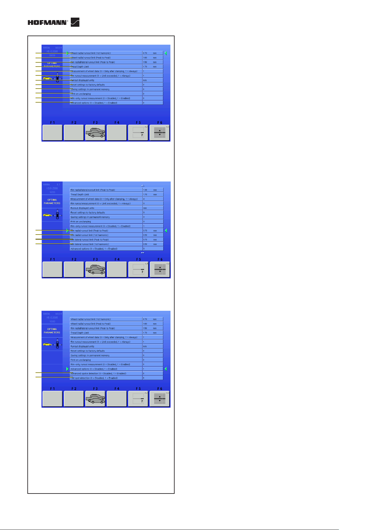
9.8 OPTIMA PARAMETERS
(fig. 9.6-1)
F5 and F6 have the same meaning of the screen relative
to the geodyna 6800 basic model.
a) Limit (threshold) for wheel first harmonic radial
runout. Preset value: 0.7 mm.
b) Limit (threshold) for wheel peak to peak radial
runout. Preset value: 1,5 mm.
c) Limit (threshold) for peak to peak radial/lateral
runout of rim only. Preset value: 1 mm.
d) Set the limit value for the Tread Depth TDI. The
scale is 0 to 10 mm (0-0,400 ince). Set the value 0
or “0,00” to disable the function; no icon appears
on screen.
Preset value: 1,7 mm (0,068 ince).
e) The wheel data detection scan occurs always during
the first measuring run. This function allows the
exclusion of the activation of the laser scanner in
the following measuring runs, in order to optimise
the operating times whenever it is necessary to
carry out more than one measuring run for the same
wheel. By assigning value “0” the scan occurs
automatically and only at the first measuring run,
after fixing the wheel. By assigning value “1” the
scan occurs automatically at every wheel
measuring run (Preset value).
f) Sets the rim runout measurement (if the value is 0
the measurement occurs only if the threshold is
exceeded; if the value is 1 the measurement
occurs always). Preset value: 0.
g) Runout measurement unit selection in mm or
inches. Preset value: mm.
h) Reset the preset default values.
i) Saves the values set by the operator.
k) Automatically prints when the wheel is removed
(only if the printer is present and active). If the
value is “0” (preset) it doesn’t print, if the value is
“1” it prints.
m) Allows selection of RIM ONLY advanced diagnosis.
Select "1" = Enables RIM ONLY advanced diagnosis
and opens the screen shown in fig. 9.6-2.
20
geodyna optima Operator’s Manual
Page 23
n1
n2
n3
n4
9.8-3
Select "0" = Enables automatic switching to the
MATCHING procedure if the machine detects the
presence of the rim only (fig. 9.6-2).
m1)Limit (threshold) for RIM ONLY peak to peak radial
Runout. Preset value: 0.7 mm.
m2)Limit (threshold) for RIM ONLY first harmonic radial
Runout. Preset value: 0.5 mm.
m3)Limit (threshold) for RIM ONLY peak to peak lateral
Runout. Preset value: 0.7 mm.
m4)Limit (threshold) for RIM ONLY first harmonic lateral
Runout. Preset value: 0.5 mm.
n) ADVANCED OPTIONS 1 and 2 (fig. 9.6-3).
“1” = Enables additional fields for managing
advanced features.
n1) Advanced Spoke Detection, activated in the OPTIMA
PARAMETERS menu, useful if the rim has complex
spokes that are difficult to identify.
“1” = Enables function. “0” = Disables function.
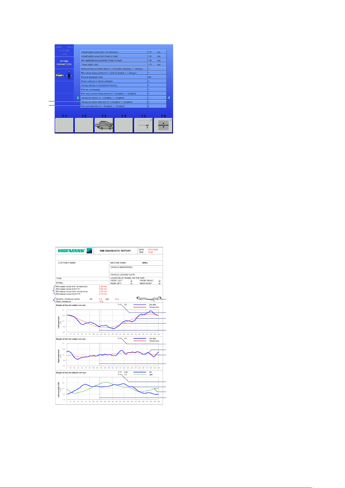
9.9 Print Report
The report print out (only possible with the optional
printer) is a summary of technical information.
The information saved during rim or rim and tire analysis
can be printed on paper in a sheet called a Report.
There are two types of Report, automatically selected
by the machine:
- Rim diagnostic report
The report print out, after a rim only run, shows the
following information:
(fig. 9.7-1)
a
b
a) Dynamic unbalance (right and left). Static
c
unbalance.
b) Limits (thresholds) for first harmonic and peak to
d
e
f
k
peak (radial/lateral) rim runout.
c) Suggested position for application of weights.
d) Left bead recess runout peak to peak value.
e) Graph of left bead recess runout (blue curve).
f) Graph of left bead recess first harmonic (red curve).
d1
d1) Right bead recess runout peak to peak value.
e1
e1) Graph of right bead recess runout (blue curve).
f1
f1) Graph of right bead recess first harmonic (red
k
curve).
g) Rim lateral runout peak to peak values (left and
g
h
i
k
9.9-1
right).
h) Graph of rim left lateral runout (blue curve).
i) Graph of rim right lateral runout (dashed green
curve).
k) Rim 12 o'clock position indicator at moment of
printing (green line).
21
Page 24
m
o1
Operational Selections
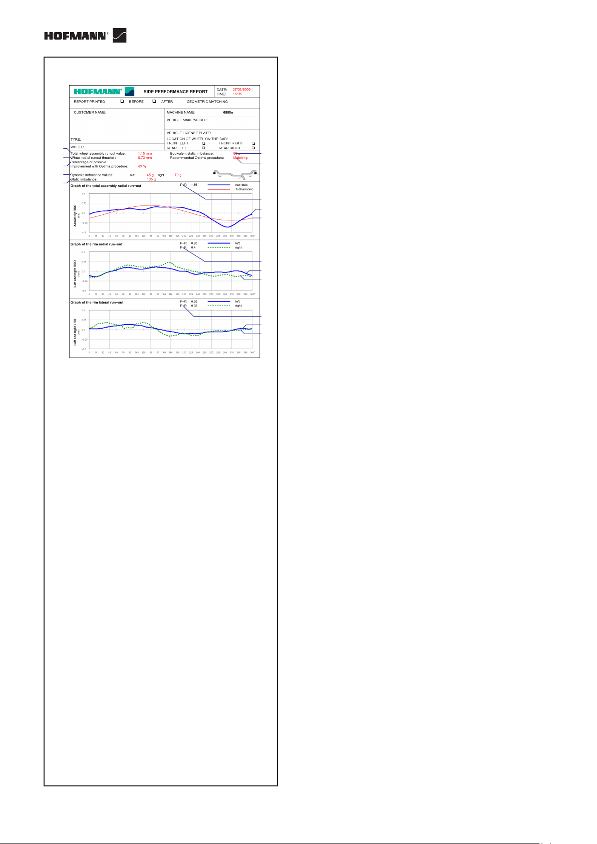
- Wheel performance report
The report print out, after a complete wheel run, shows
the following information:
(fig. 9.7-2)
j) Rim - tire assembly total runout value.
m) Wheel radial runout threshold value.
j
p
q
9.9-2
n) Equivalent Static Unbalance, induced by Runout
n
o
r
n
n
n
v
w
x
v1
w1
x1
measured.
o) Recommended Optima procedure.
o1) Percentage improvement which can be achieved
using recommended Optima procedure.
p) Dynamic Unbalance measured (right and left).
q) Static Unbalance calculated from dynamic
components measured.
r) Suggested position for application of weights.
s) Complete wheel radial runout peak to peak value.
t) Graph of complete wheel radial runout (blue curve).
u) Graph of wheel total first harmonic (red curve).
v) Rim (left and right) radial runout peak to peak
values.
w) Graph of rim left radial runout (blue curve).
x) Graph of rim right radial runout (dashed green
curve).
v1) Rim (left and right) lateral runout peak to peak
values.
w1) Graph of rim left lateral runout (blue curve).
x1) Graph of rim right lateral runout (dashed green
curve).
22
10.0 Changing modes of
operation
See geodyna 6800 basic model instructions.
geodyna optima Operator’s Manual
Page 25
11.0-1
11.0 Optional functions
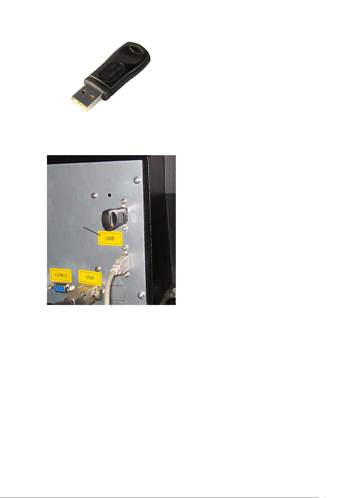
The wheel balancer has additional functions, which can
be enabled individually after purchasing the machine.
They are enabled by plugging a software key (fig. 11.0-
1) into one of the USB ports on the back of the machine
(fig. 11.0-2).
Each USB key acts exclusively as an enabling device
and its presence on the machine is essential in order
to use the Optional Functions. The USB key must
remain plugged in constantly until the cycle of the
Function it enables is complete.
You can plug in the key at any moment. The program
recognises the key immediately and the Optional
Function is instantly made available, without the
operator having to perform any other procedures.
The key can also be removed at any moment, disabling
any Optional Functions.
A
THE OPTIONAL FUNCTIONS ARE ONLY ACTIVE
WHEN THE USB KEY IS PLUGGED INTO THE
MACHINE'S USB PORT.
AS SOON AS THE KEY IS REMOVED FROM THE
USB PORT THE OPTIONAL FUNCTIONS ARE NO
LONGER AVAILABLE ON THE MACHINE.
How to use the key:
• Plug the key into one of the USB ports, shown by the
yellow sticker (A fig. 11.0-2), on the back of the
machine.
11.0-2
Keep the key by leaving it plugged into the machine's
USB port.
23
Page 26
Operational Selections
11.1 OPTI LINE mode
The OPTI LINE mode is a computerised function
designed to improve the vehicle "PULL" effect, that is
to say, the lateral pull force caused by excessive tread
conicity, as well as to minimise the vibrations caused
by any residual wheel unbalance.
Note: is an optional function which must
be requested and enabled separately.
With the OPTI LINE mode (function only possible in
OPTIMA mode) the balancer analyses a set of wheels,
saving their tread conicity index. When the procedure
is complete the machine selects the best four wheels,
suggesting the order in which they should be mounted
to minimise the lateral pull force they produce on the
moving vehicle.
The "PULL" effect caused by excessive tread conicity,
which cannot be corrected by means of wheel
positioning, can be eliminated thanks to Optima's OPTI
LINE mode, using the "Set of Wheels" procedure.
11.1-1
Start the "Set of Wheels" procedure and the run, then
complete compensation of the unbalance, remove the
wheel from the balancer and finally assign the wheel to
the Set, saving its data. When the procedure is
complete, repeat these operations for up to five wheels.
When the fourth wheel is assigned to the Set, a
suggestion for mounting on the vehicle is provided,
allowing you to conclude the procedure. After entry of
the fifth wheel, the program selects and proposes the
best four wheels with the relative mounting suggestion.
Procedure:
• Check that the key which enables the Optional
Function is plugged in. See section 11.0.
Note: The OptiLine mode is active on the machine
when the specific USB key is plugged in.
If the key is removed the Function is not
available.
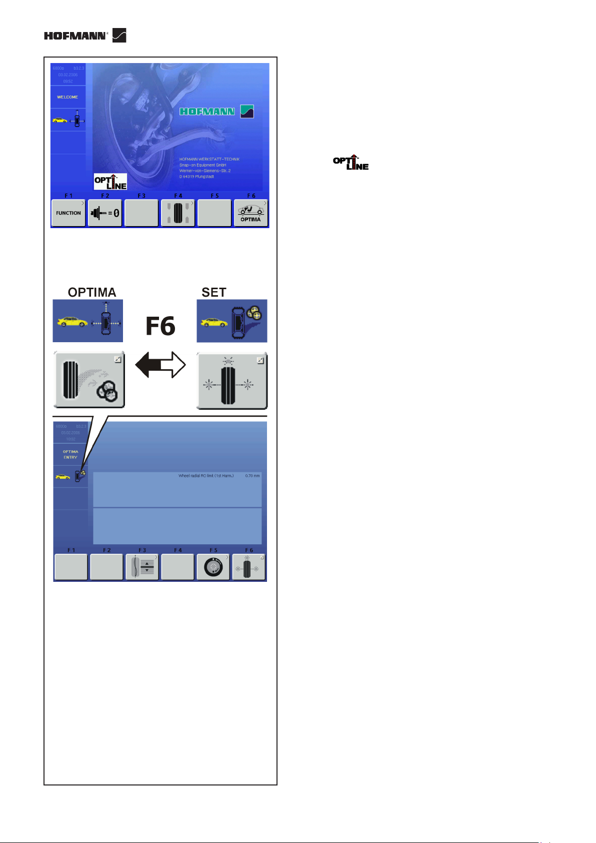
• Check that OPTIMA mode is switched on.
• Press F6 to go to the OPTIMA ENTRY SCREEN.
• Press F6 to switch on the Set of Wheels
procedure.
24
Note: When the "Set of Wheels" procedure is on,
the status bar shows the relative icon (Fig.
11.1-1) and key F6 shows the OPTIMA icon
again for exiting and returning to OPTIMA
mode.
geodyna optima Operator’s Manual
Page 27
WHEEL No. 1
123
The balancer completes the optima program readings,
then the rear laser scanner scans the tread to acquire
the conicity indices.
11.1-2
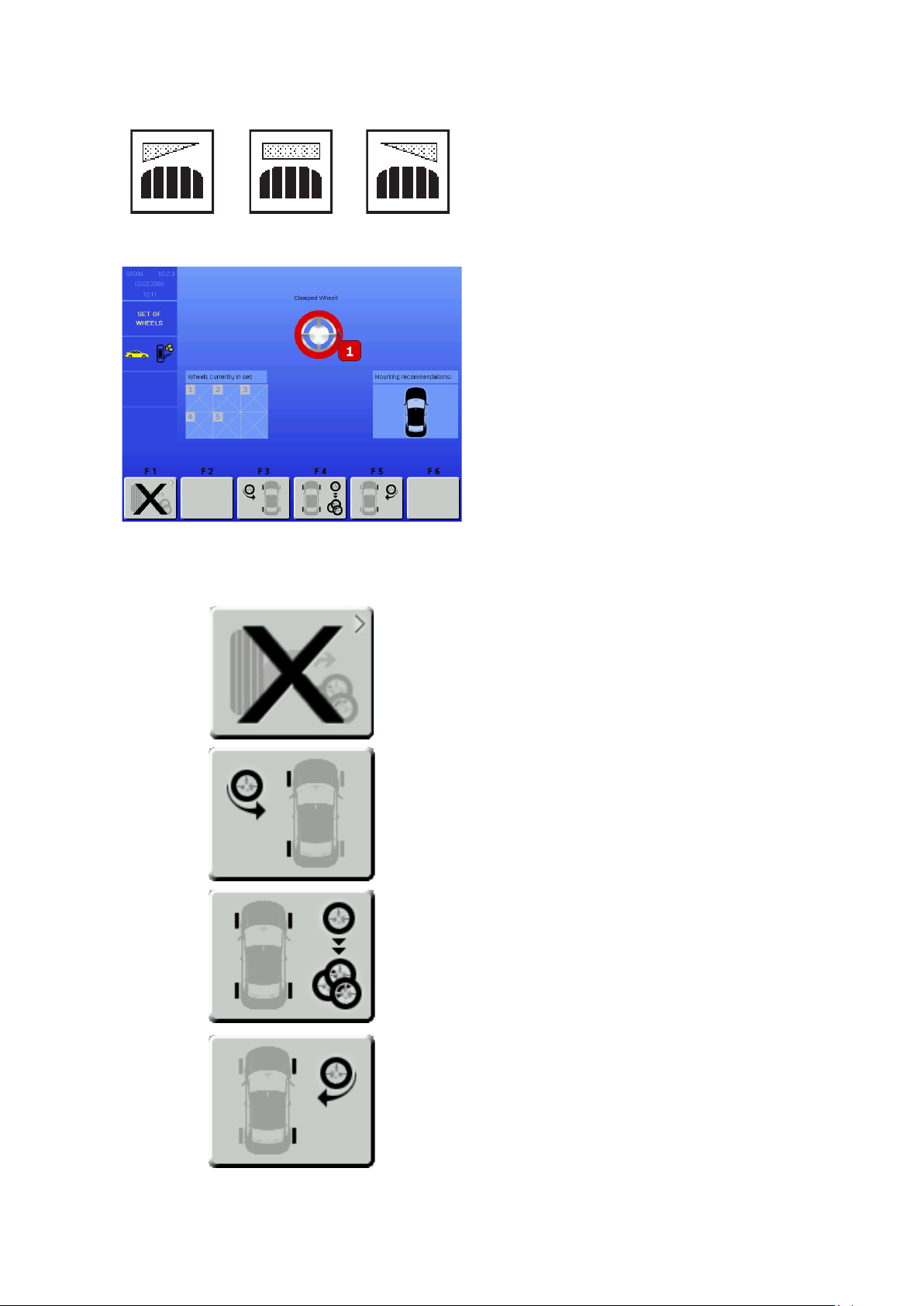
The icon indicating the tread conicity angle appears on
the OPTIMA ENTRY screen page (Fig. 11.1-2).
The meanings of the icons are as follows:
1) Tread conicity reading with pull towards LEFT.
2) Tread conicity reading with NEUTRAL pull.
3) Tread conicity reading with pull towards RIGHT.
• Mount the wheel on the balancer shaft.
• Perform the run.
Note: The overall cycle time is increased by this
operation.
F1
F3
F4
11.1-3
• Balance the planes and make any corrections
suggested by optima.
• Remove the wheel from the balancer.
When you remove the wheel, the screen shows a
number and a colour assigned to the wheel, useful for
identifying it until the procedure is complete (Fig. 11.1-
3).
From this moment the keys in the control bar have the
following functions (Fig. 11.1-4):
Key F1
EXIT the Set of Wheels program; the data acquired up
to this point is definitively deleted. The machine returns
to the OPTIMA ENTRY screen and stands by for further
commands.
Key F3
ENTER a wheel which can be mounted only on the left
of the vehicle; tyres with mandatory direction.
Key F4
ENTER a wheel without direction constraints, which
can therefore be used on either side of the vehicle.
F5
Key F5
ENTER wheels which can only be mounted on the right
of the vehicle; tyres with mandatory direction.
11.1-4
25
Page 28
F2
11.1-5
Operational Selections
To continue,
• Select one of the keys F3, F4 or F5 to add the
wheel to the Set, assigning the mandatory side
mounting position if necessary.
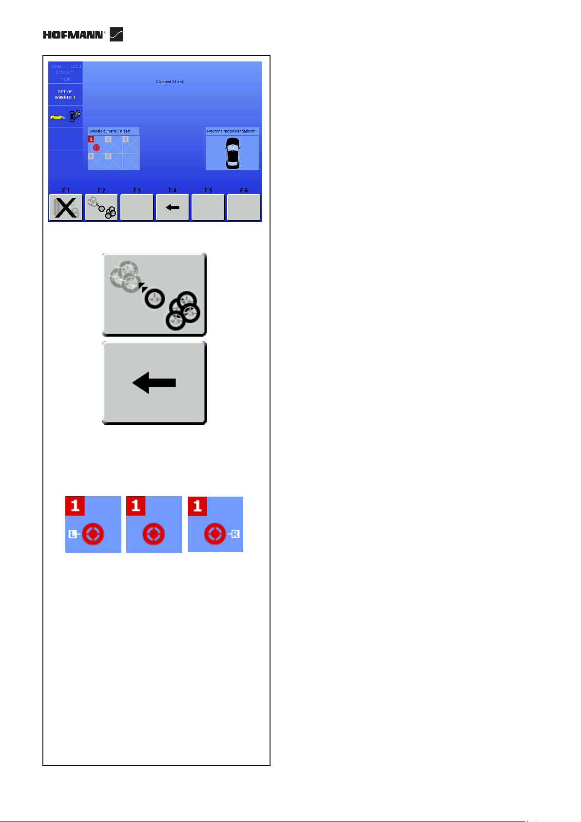
The "SET OF WHEELS 1" screen page appears
automatically (Fig. 11.1-5).
The screen page shows new keys, for moving
backwards in the Set of Wheels procedure (Fig. 11.1-
6):
Key F2
Deletes the current Set and starts a new "Set of
Wheels".
The last wheel examined will be kept and automatically
proposed again as wheel number 1 of the new Set.
Note: Starting with wheel No. 2, the key will be
available for wheel removal, as an
alternative to entry keys F3, F4, F5.
Key F4
RETURN to the previous step, so that you can assign
the wheel a different use in the Set.
F4
11.1-6
12 3
11.1-7
The wheels definitively acquired in the memory are
represented by icons grouped in the "Wheels Currently
in the Set" box. These icons also show any specific
mandatory position assigned as described (Fig. 11.1-
7):
1) Wheel assigned only to left side of vehicle.
2) Wheel available for both sides of vehicle.
3) Wheel assigned only to right side of vehicle.
To continue,
• Apply the appropriate identification tag to the
wheel valve, with the same number and colour
as the last wheel shown (Fig. 11.1-8).
26
11.1-8
geodyna optima Operator’s Manual
Page 29
WHEEL No. 2
• Mount the wheel on the balancer shaft.
• Perform the run.
• Balance the planes and make any corrections
suggested by optima.
• Remove the wheel from the balancer.
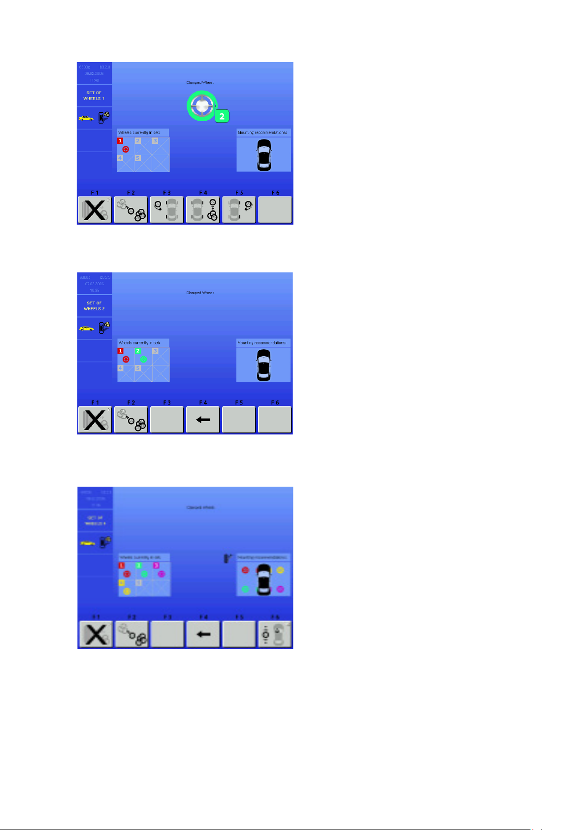
The screen page shows the wheel with the number after
the previous one and a different colour (Fig. 11.1-9).
• Select one of the keys F3, F4 or F5 to enter the
current wheel in the set.
The "SET OF WHEELS 2" screen page appears
automatically (Fig. 11.1-10).
11.1-9
11.1-10
Note: After selecting key F3 or key F5 twice in the
procedure, the program does not allow
you to select this key again.
You cannot assign more than two wheels
to the same side of the vehicle.
WHEEL No. 3
• Perform the procedure as described for wheel
No. 2.
WHEEL No. 4
• Perform the procedure as described for wheel
No. 2.
At this point of the procedure the machine already has
a first mounting suggestion.
The box on the right shows the number and colour of
each wheel in the appropriate mounting position on the
vehicle (Fig. 11.1-11) for optimising the PULL.
11.1-11
You can now select one of these options:
"Optimise vibrations",
"Enter fifth wheel"
"Start a new Set of Wheels", or
"Terminate and exit procedure"
as described below.
27
Page 30
F6
11.1-12
Operational Selections
Optimise vibrations
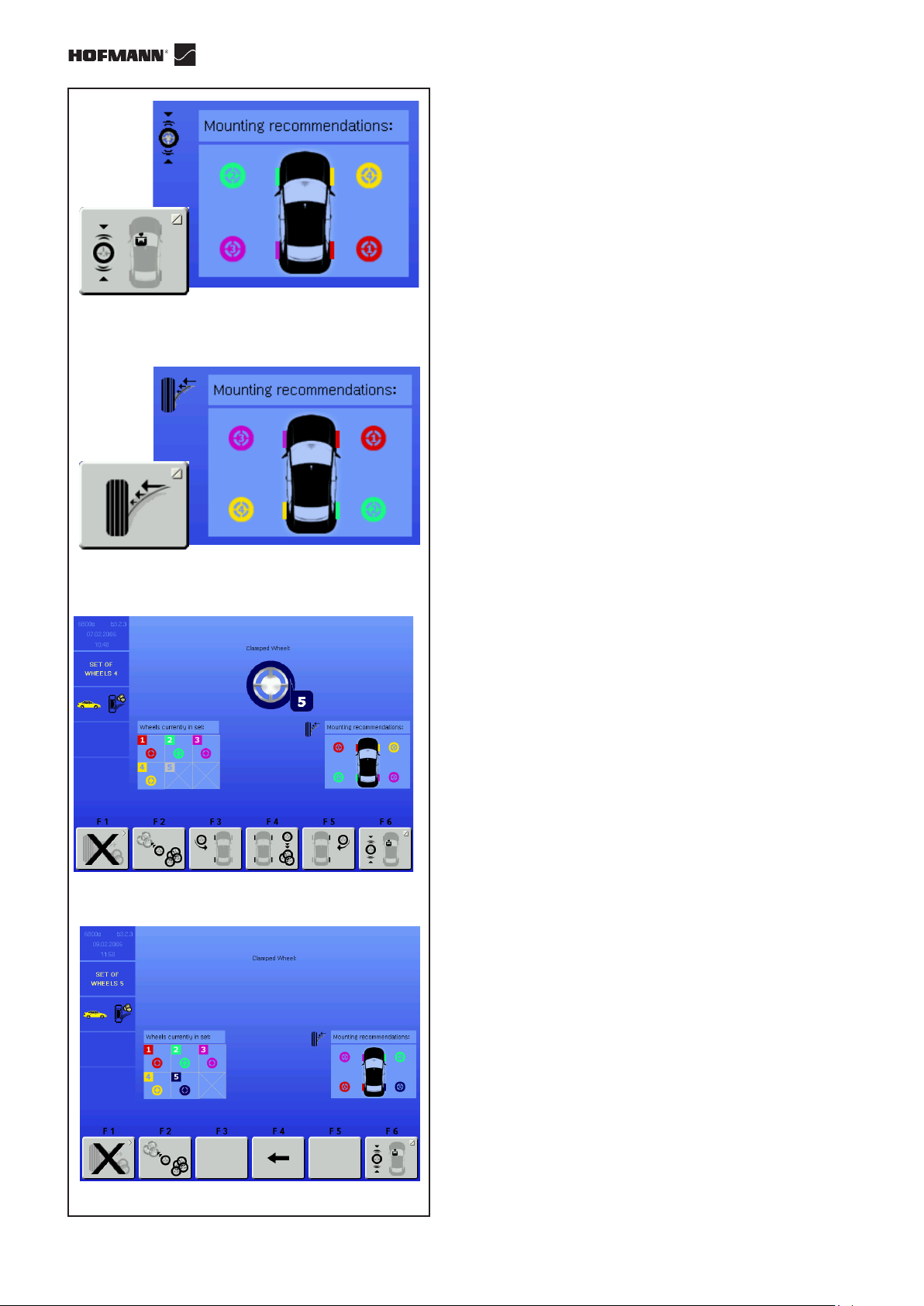
As an alternative to the mounting recommendation for
the set of wheels to minimise the PULL, you can select
a different set-up, suggested to reduce the vibrations
caused by any residual unbalance on the wheels in the
Set.
• Press key F6 to view the recommended
mounting option for optimising vibrations (Fig.
11.1-12).
If you follow this mounting diagram the driver's side of
the vehicle will benefit by feeling the least possible
vibrations.
Note: The different mounting suggestions which can
be selected are not correlated.
You must choose one of the recommended
mounting options, depending on the
priority correction requirement for the
vehicle in question.
• Press key F6 again to view the mounting
recommendation for PULL optimisation seen
before (Fig. 11.1-13).
F6
11.1-13
11.1-14
Note: Key F6 allows you to toggle between the
different mounting options.
The icon on the top left of the screen
indicates the type of optimisation referred
to by the mounting order shown at that
time.
Enter fifth wheel
(Fig. 11.1-14)
The Set of Wheels procedure in the OPTI LINE mode
allows the entry of a fifth wheel in the set, to guarantee
greater scope for improvement.
WHEEL No. 5
• Perform the procedure as described for wheel
No. 2.
When you enter the 5th wheel in the Set the "SET OF
WHEELS 5" screen page appears automatically (Fig.
11.1-15) and the selection of the best four wheels is
shown, with their relative positions on the vehicle, taken
from the set of five wheels processed.
28
Note: No further wheels can be entered in the Set.
If you try to enter another wheel the
machine starts the procedure for a new
Set of Wheels and all of the data relative
to the previous Set will be deleted.
11.1-15
geodyna optima Operator’s Manual
Page 31
Start a new Set of Wheels
After entry of WHEEL No. 5 in a Set, you can start a
new Set, without exiting the Set of Wheels mode.
Proceed as follows:
• Perform the procedure as described for wheel
No. 1.
The machine deletes the data relative to the previous
wheels and shows the current wheel as the first wheel
in a new Set.
After entry of WHEEL No. 4 in a Set you can start a
new Set, without exiting the Set of Wheels mode.
Proceed as follows:
F2
F1
11.1-14
11.1-6
• Mount the wheel on the balancer shaft.
• Perform the run.
• Complete any normal correction and balancing
operations required.
• Remove the wheel from the balancer.
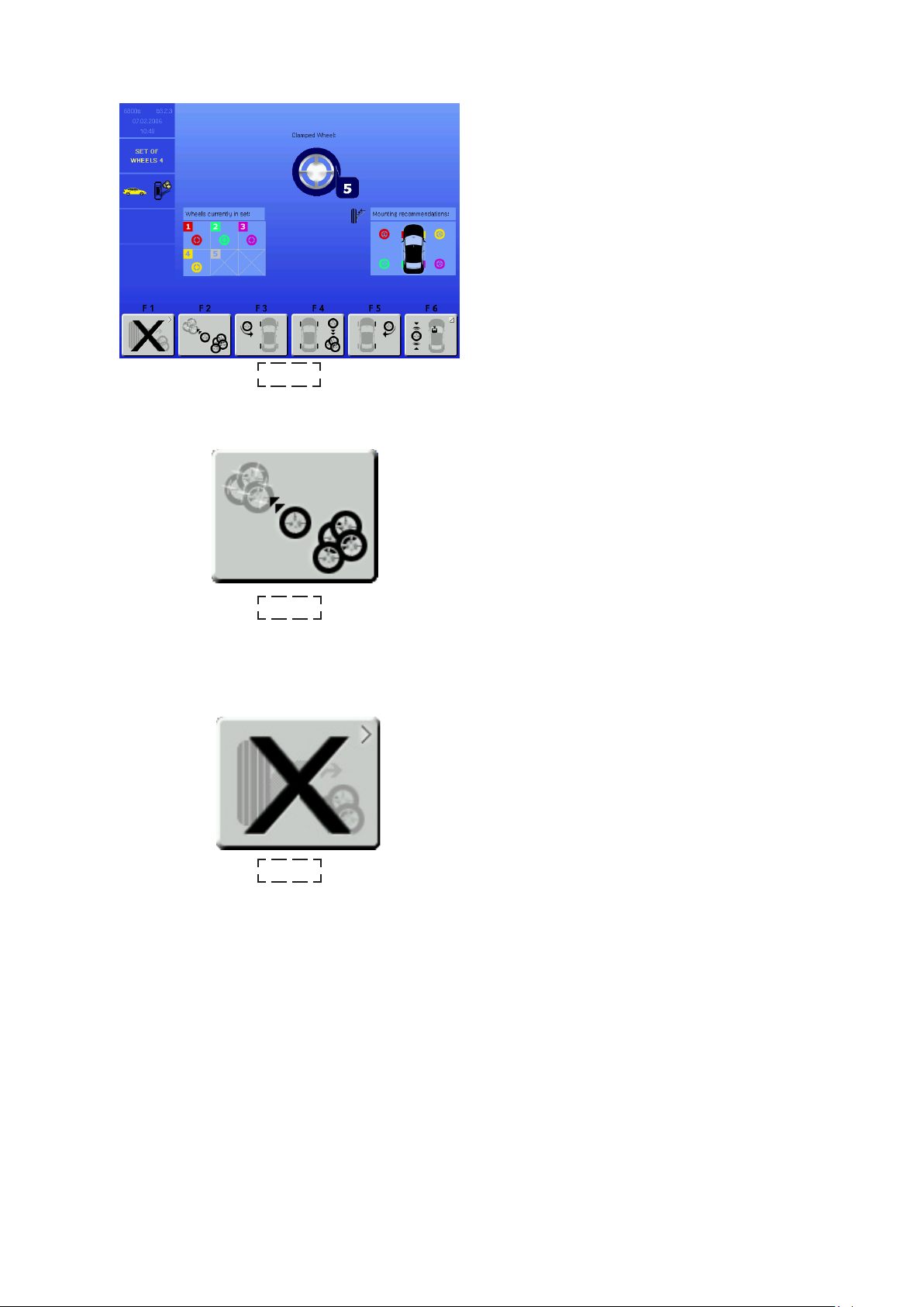
Wheel number 5 is shown on the screen page (Fig.
11.1-14).
• Press key F2 (Fig. 11.1-6).
The machine deletes the data relative to the previous
wheels and shows the last wheel as wheel number 1,
starting a new Set of Wheels.
Terminate and exit procedure
To exit the Set of Wheels procedure and return to the
OPTIMA ENTRY screen page.
• Press key F1 (Fig. 11.1-4).
All data relative to the Set of Wheels is deleted.
11.1-4
29
Page 32
11.1.1-1
Operational Selections
11.1.1 PULL calibration
The PULL calibration procedure is available if the OPTI
LINE mode is installed.
This procedure is for checking and correcting any
parallax problems between the rear scanner running
plane and the axis of the machine wheel shaft, to
guarantee precision measurement of the tread conicity
indices.
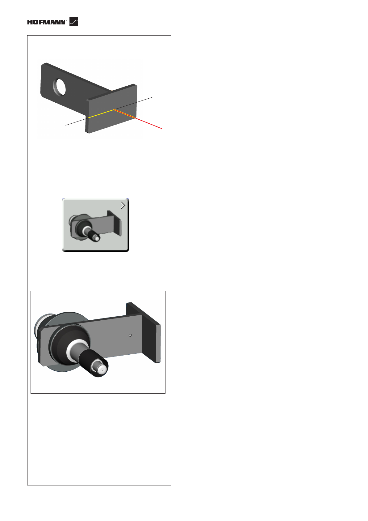
The procedure uses the special Calibration Tool
supplied, on whose front surface the rear laser's beam
must run (Fig. 11.1.1-1).
CAUTION: HANDLE THE CALIBRATION TOOL
WITH CARE. AVOID BUMPS AND KEEP IN A SAFE
PLACE.
Calibration must be carried out regularly.
When using the Set of Wheels procedure, the last
calibration should have been performed within a month.
F1
11.1.1-2
H
11.1.1-3
To perform the PULL calibration, proceed as follows:
• Open the OPTIMA screen page (F6).
• Select key F3 to open the OPTIMA
PARAMETERS screen page.
• Select key F1 (Fig. 11.1.1-2).
• Install the Calibration Tool so that the blind hole
used as a reference faces the outside of the
machine, as illustrated (H, Fig. 11.1.1-3).
• Turn the front surface of the Tool towards the
back of the balancer, angle the plate towards
the scanner, then lock it in position using the
pedal brake.
• Lower the wheel guard.
• Press F6 to start calibration.
The rear scanner starts up, starting the calibration.
If the difference between the PULL index calculated by
the user calibration and the value set by the factory
calibration is less than 0.5, the operation ends with a
positive result and the text OK appears.
If not, error E400 is signalled (see "Error Messages"
section).
30
• Remove the calibration tool.
Note: For an on-line description of the procedure
select the HELP key in the OPTIMA
PARAMETERS screen page.
geodyna optima Operator’s Manual
Page 33

12.0 Error codes
Note: E Prefix = Errors in operation
H Prefix = Warnings
The error codes are displayed for ca. 3 seconds on
the left of the screen above the F1 menu key with an
E followed by the numerical code (e.g. E10).
Use the HELP key to call up a help text (installed as
of version 1.34 of the software).
• To cancel the error message, the error must be
removed (e.g. open the wheel guard) or press the
STOP or ESC key.
The error messages with reference to the optima wheel
balancer functionality are described below:
E1
Rim dimensions incorrect or incomplete.
• Repeat rim data input.
• If the problem persists, you can have a manual
data entry by pressing F1 in the balancing
screen.
E30
No runout detection.
• Repeat the measuring run to determine the
runout detection.
• If the problem persists call service.
E31
If the operator, following a rim profile reading,
chooses to proceed with a complete wheel
measurement, the control software prevents the
operation because only the presence of the rim is
detected.
• Fit a tire on the rim.
E32
The user selected to proceed with a bare rim
measurement but the machine actually detects
that a complete wheel is on the machine.
• Mount a bare rim.
31
Page 34

Error Codes
E40
Printing error. Check that:
• the printer is connected to the balancer;
• the printer is switched on;
• there is paper.
• If the problem persists, reset the printer by
disconnecting and connecting the power supply
cable.
E360
Wheel profiler position calibration required
Possible causes:
• the camera controller board has been replaced
• at least one scanner has been replaced
• the calibration data is missing
• the scanner cables have been swapped
Corrective actions:
• check the connections
• calibration procedure (C122) is required to
calibrate the actual position of the laser
scanners with respect to the balancer reference
plane.
E361
Wheel profiler not present or not responding
during self test
The balancer controller board was not able to
communicate with the camera controller board during
power on self test.
Possible causes:
• the camera controller board is missing or
damaged
• the flat cable connecting the keyboard, the
balancer controller board and the camera
controller board is unplugged, damaged or
missing
Corrective actions:
• check the camera controller board
• check the connections
• re-install the camera controller board software.
32
geodyna optima Operator’s Manual
Page 35

E362
Main camera board power on self test failure
Possible causes:
• there is a fault in the camera controller board
• the flat cable connecting the keyboard, the
balancer controller board and the camera
controller board is partially unplugged or
damaged
• the supply voltage is not configured properly
on the power interface board
Corrective actions:
• check the camera controller board
• check the connections
• check the supply voltage with service code
C110.
E363
Left scanner self test failed, CCD not reset or zero point
mark not detected.
The balancing is not possible as the laser scanners
cannot detect the wheel data.
Problems have occurred at power-on.
• Switch off and power-on again.
• If the problem persists call service.
E364
Right scanner self test failed, CCD not reset or zero
point mark not detected.
The balancing is not possible as the laser scanners
cannot detect the wheel data.
Problems have occurred at power-on.
• Switch off and power-on again.
• If the problem persists call service.
33
Page 36

Error Codes
E365
Rear scanner self test failed, CCD not reset or zero
point mark not detected.
The laser scanners can detect the wheel data: the
balancing is possible, but the runout measurement
cannot be carried out.
Problems have occurred at power-on.
• Switch off and power-on again.
• If the problem persists call service.
E366
Main camera board memory self test failure
Possible causes:
• there is a fault in the camera controller board
Corrective actions:
• check the camera controller board.
E367
Motor power supply missing or out of range
Possible causes:
• the cable connecting the camera controller
board and the motor power supply is
unplugged, damaged or missing
• the motor power supply is not configured
properly
• there is a fault in the motor power supply board
• the cable connecting the mains supply and the
motor power supply board is unplugged,
damaged or missing
Corrective actions:
• check all items above.
E368
Main camera board A/D converter failure
Possible causes:
• there is a fault in the camera controller board
Corrective actions:
• check the camera controller board.
34
E369
Main shaft encoder zero mark detection failure or
missing cable
Possible causes:
• there is a fault in the camera controller board
• there is a fault in the encoder
geodyna optima Operator’s Manual
Page 37

• the cable connecting the camera controller
board and the encoder board is unplugged,
missing or damaged
Corrective actions:
• check the camera controller board
• check the encoder
• check the connections.
E370
Inner CCD signals failure
Possible causes:
• the flat cable connecting the camera controller
board and the inner scanner CCD board is
unplugged, missing or damaged
• there is a fault in the inner scanner CCD board
• there is a fault in the camera controller board
• the supply voltage is configured too high on
the power interface board
Corrective actions:
• check all items above
• switch power off and on again; should the
problem not go away please call service.
E371
Inner scanner memory not responding
Possible causes:
• the flat cable connecting the camera controller
board and the inner scanner CCD board is
unplugged, missing or damaged
• there is a fault in the inner scanner CCD board
• there is a fault in the camera controller board
Corrective actions:
• check the connections
• check the inner scanner CCD board
• check the camera controller board
• switch power off and on again; should the
problem not go away please call service.
E372
Inner scanner memory not valid
Possible causes:
• the flat cable connecting the camera controller
board and the inner scanner CCD board is
partially unplugged or damaged
• there is a fault in the inner scanner CCD board
Corrective actions:
• check the connections
35
Page 38

Error Codes
• check the inner scanner CCD board
• switch power off and on again; should the
problem not go away please call service.
E373
Inner scanner not calibrated
Possible causes:
• the inner scanner has not been factory
calibrated
Corrective actions:
• please call service and replace the inner
scanner.
E374
Inner motor current sink or power supply failure
Possible causes:
• the cable connecting the camera controller
board and the inner scanner motor is
unplugged, damaged or missing
• the motor power supply is not configured
properly
• there is a fault in the motor power supply board
• the cable connecting the mains supply and the
motor power supply board is unplugged,
damaged or missing
• there is a fault in the inner scanner motor
• there is a fault in the camera controller board
motor drivers
Corrective actions:
• check all items above.
E375
Inner scanner zero mark not detected
Possible causes:
• the flat cable connecting the camera controller
board and the inner scanner CCD board is
unplugged, missing or damaged
• there is a fault in the inner scanner CCD board
• the inner scanner is locked
• the inner scanner zero mark is missing, bent,
locked or damaged
• the cable connecting the camera controller
board and the inner scanner motor is
unplugged, damaged or missing
• there is a fault in the motor power supply board
• there is a fault in the inner scanner motor
• there is a fault in the camera controller board
motor drivers
Corrective actions:
• check all items above.
36
geodyna optima Operator’s Manual
Page 39

E376
Inner motor missing steps
Possible causes:
• the inner scanner movement is not smooth or
it is striking the frame
• the motor power supply is not configured
properly
• there is a fault in the motor power supply board
• there is a fault in the inner scanner motor
• there is a fault in the camera controller board
motor drivers
• the cable connecting the camera controller
board and the inner scanner motor is partially
unplugged or damaged
Corrective actions:
• check all items above.
E377
Inner laser current sink or power supply failure
Possible causes:
• the flat cable connecting the camera controller
board and the inner scanner CCD board is
unplugged, missing or damaged
• the cable of the laser module of the inner
scanner is damaged or there is a fault in the
laser module itself
• there is a fault in the camera controller board
laser drivers
Corrective actions:
• check all items above.
E378
Inner laser modulation failure
Possible causes:
• the flat cable connecting the camera controller
board and the inner scanner CCD board is
unplugged, missing or damaged
• the cable of the laser module of the inner
scanner is damaged or there is a fault in the
laser module itself
• there is a fault in the camera controller board
laser drivers
Corrective actions:
• check all items above.
37
Page 40

Error Codes
E380
Outer CCD signals failure
Possible causes:
• the flat cable connecting the camera controller
board and the outer scanner CCD board is
unplugged, missing or damaged
• there is a fault in the outer scanner CCD board
• there is a fault in the camera controller board
• the supply voltage is configured too high on
the power interface board
Corrective actions:
• check all items above
• switch power off and on again; should the
problem not go away please call service.
E381
Outer scanner memory not responding
Possible causes:
• the flat cable connecting the camera controller
board and the outer scanner CCD board is
unplugged, missing or damaged
• there is a fault in the outer scanner CCD board
• there is a fault in the camera controller board
Corrective actions:
• check the connections
• check the outer scanner CCD board
• check the camera controller board
• switch power off and on again; should the
problem not go away please call service.
E382
Outer scanner memory not valid
Possible causes:
• the flat cable connecting the camera controller
board and the outer scanner CCD board is
partially unplugged or damaged
• there is a fault in the outer scanner CCD board
Corrective actions:
• check the connections
• check the outer scanner CCD board
• switch power off and on again; should the
problem not go away please call service.
38
geodyna optima Operator’s Manual
Page 41

E383
Outer scanner not calibrated
Possible causes:
• the outer scanner has not been factory
calibrated
Corrective actions:
• please call service and replace the outer
scanner.
E384
Outer motor current sink or power supply failure
Possible causes:
• the cable connecting the camera controller
board and the outer scanner motor is
unplugged, damaged or missing
• the motor power supply is not configured
properly
• there is a fault in the motor power supply board
• the cable connecting the mains supply and the
motor power supply board is unplugged,
damaged or missing
• there is a fault in the outer scanner motor
• there is a fault in the camera controller board
motor drivers
Corrective actions:
• check all items above.
E385
Outer scanner zero mark not detected
Possible causes:
• the flat cable connecting the camera controller
board and the outer scanner CCD board is
unplugged, missing or damaged
• there is a fault in the outer scanner CCD board
• the outer scanner is locked
• the outer scanner zero mark is missing, bent,
locked or damaged
• the cable connecting the camera controller
board and the outer scanner motor is
unplugged, damaged or missing
• there is a fault in the motor power supply board
• there is a fault in the outer scanner motor
• there is a fault in the camera controller board
motor drivers
Corrective actions:
• check all items above.
39
Page 42

Error Codes
E386
Outer motor missing steps
Possible causes:
• the outer scanner movement is not smooth or
it is striking the frame
• the motor power supply is not configured
properly
• there is a fault in the motor power supply board
• there is a fault in the outer scanner motor
• there is a fault in the camera controller board
motor drivers
• the cable connecting the camera controller
board and the outer scanner motor is partially
unplugged or damaged
Corrective actions:
• check all items above.
E387
Outer laser current sink or power supply failure
Possible causes:
• the flat cable connecting the camera controller
board and the outer scanner CCD board is
unplugged, missing or damaged
• the cable of the laser module of the outer
scanner is damaged or there is a fault in the
laser module itself
• there is a fault in the camera controller board
laser drivers
Corrective actions:
• check all items above.
E388
Outer laser modulation failure
Possible causes:
• the flat cable connecting the camera controller
board and the outer scanner CCD board is
unplugged, missing or damaged
• the cable of the laser module of the outer
scanner is damaged or there is a fault in the
laser module itself
• there is a fault in the camera controller board
laser drivers
Corrective actions:
• check all items above.
40
geodyna optima Operator’s Manual
Page 43

E390
Rear CCD signals failure
Possible causes:
• the flat cable connecting the camera controller
board and the rear scanner CCD board is
unplugged, missing or damaged
• there is a fault in the rear scanner CCD board
• there is a fault in the camera controller board
• the supply voltage is configured too high on
the power interface board
Corrective actions:
• check all items above
• switch power off and on again; should the
problem not go away please call service.
E391
Rear scanner memory not responding
Possible causes:
• the flat cable connecting the camera controller
board and the rear scanner CCD board is
unplugged, missing or damaged
• there is a fault in the rear scanner CCD board
• there is a fault in the camera controller board
Corrective actions:
• check the connections
• check the rear scanner CCD board
• check the camera controller board
• switch power off and on again; should the
problem not go away please call service.
E392
Rear scanner memory not valid
Possible causes:
• the flat cable connecting the camera controller
board and the rear scanner CCD board is
partially unplugged or damaged
• there is a fault in the rear scanner CCD board
Corrective actions:
• check the connections
• check the rear scanner CCD board
• switch power off and on again;
• should the problem not go away please call
service.
41
Page 44

Error Codes
E393
Rear scanner not calibrated
Possible causes:
• the rear scanner has not been factory calibrated
Corrective actions:
• please call service and replace the rear
scanner.
E394
Rear motor current sink or power supply failure
Possible causes:
• the cable connecting the camera controller
board and the rear scanner motor is unplugged,
damaged or missing
• the motor power supply is not configured
properly
• there is a fault in the motor power supply board
• the cable connecting the mains supply and the
motor power supply board is unplugged,
damaged or missing
• there is a fault in the rear scanner motor
• there is a fault in the camera controller board
motor drivers
Corrective actions:
• check all items above.
E395
Rear scanner zero mark not detected
Possible causes:
• the flat cable connecting the camera controller
board and the rear scanner CCD board is
unplugged, missing or damaged
• there is a fault in the rear scanner CCD board
• the rear scanner is locked
• the rear scanner zero mark is missing, bent,
locked or damaged
• the cable connecting the camera controller
board and the rear scanner motor is unplugged,
damaged or missing
• there is a fault in the motor power supply board
• there is a fault in the rear scanner motor
• there is a fault in the camera controller board
motor drivers
Corrective actions:
• check all items above.
42
geodyna optima Operator’s Manual
Page 45

E396
Rear motor missing steps
Possible causes:
• the rear scanner movement is not smooth or it
is striking the frame
• the motor power supply is not configured
properly
• there is a fault in the motor power supply board
• there is a fault in the rear scanner motor
• there is a fault in the camera controller board
motor drivers
• the cable connecting the camera controller
board and the rear scanner motor is partially
unplugged or damaged
Corrective actions:
• check all items above.
E397
Rear laser current sink or power supply failure
Possible causes:
• the flat cable connecting the camera controller
board and the rear scanner CCD board is
unplugged, missing or damaged
• the cable of the laser module of the rear
scanner is damaged or there is a fault in the
laser module itself
• there is a fault in the camera controller board
laser drivers
Corrective actions:
• check all items above.
E398
Rear laser modulation failure
Possible causes:
• the flat cable connecting the camera controller
board and the rear scanner CCD board is
unplugged, missing or damaged
• the cable of the laser module of the rear
scanner is damaged or there is a fault in the
laser module itself
• there is a fault in the camera controller board
laser drivers
Corrective actions:
• check all items above.
43
Page 46

Error Codes
E400
Pull index user calibration failure
The pull index user calibration performs a scanning of
the flat surface of the calibration flange and calculates
a pull index.
This is compared with the factory/service calibration
(step 7 of C122):
• if the difference is less then 0.5 degrees, OK
is displayed and the user calibrated pull index
overrides the factory/service value for set of
wheels calculations;
• if the difference is more then 0.5 degrees, the
error code E400 is displayed and a service call
is suggested; the machine still runs using the
most recent factory/service calibrated pull
index. This might result in a slight inaccuracy
of the conicity measurement.
Corrective actions:
• press F6 to repeat the procedure
press ESC or STOP to release the brake and exit
the procedure.
E404
Rear shift motor current sink or power supply
failure
Possible causes:
• the cable connecting the camera controller
board and the rear shift scanner motor is
unplugged, damaged or missing
• the motor power supply is not configured
properly
• there is a fault in the motor power supply board
• the cable connecting the mains supply and the
motor power supply board is unplugged,
damaged or missing
• there is a fault in the rear shift scanner motor
• there is a fault in the camera controller board
motor drivers.
Corrective actions:
• check all items above.
44
geodyna optima Operator’s Manual
Page 47

E405
Rear shift scanner zero mark not detected
Possible causes:
• the flat cable connecting the camera controller
board and the rear shift scanner CCD board is
unplugged, missing or damaged
• there is a fault in the rear shift scanner CCD
board
• the rear shift scanner is locked
• the rear shift scanner zero mark is missing,
bent, locked or damaged
• the cable connecting the camera controller
board and the rear shift scanner motor is
unplugged, damaged or missing
• there is a fault in the motor power supply board
• there is a fault in the rear shift scanner motor
• there is a fault in the camera controller board
motor drivers
Corrective actions:
• check all items above.
E406
Rear shift motor missing steps
Possible causes:
• the rear shift scanner movement is not smooth
or it is striking the frame
• the motor power supply is not configured
properly
• there is a fault in the motor power supply board
• there is a fault in the rear shift scanner motor
• there is a fault in the camera controller board
motor drivers
• the cable connecting the camera controller
board and the rear shift scanner motor is
partially unplugged or damaged
Corrective actions:
• check all items above.
45
Page 48

Error Codes
E623
Error in virtual dimensions calculation
The distance of the left virtual compensation plane from
the reference plane in the measuring system is incorrect.
One of the unbalance sensors may have been mounted
with inverted polarity.
• Check and correct if connection is wrong.
46
geodyna optima Operator’s Manual
Page 49

13.0 Optimisation / Weight
minimisation
See geodyna 6800 basic model instructions (function
can only be carried out in Manual mode).
14.0 Readjustment by the
operator
See geodyna 6800 basic model instructions.
47
Page 50
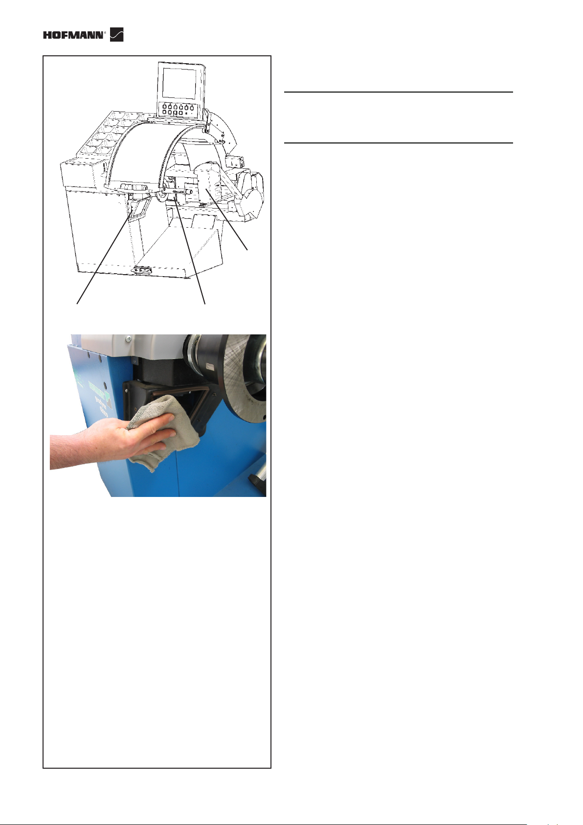
Maintenance, technical data
15.0 Maintenance
WARNING: PRIOR TO MAINTENANCE OR REPAIR
WORKDISCONNECT THE MACHINE FROM THE
MAINS SUPPLY AND PROTECT AGAINST
UNINTENTIONALSWITCHING ON.
Note: refer to the geodyna 6800 basic model
instructions for all the maintenance and
cleaning operations.
2
1
15.1-1
3
15.1 Laser scanners seating glass
cleaning
The laser scanners seats (fig. 16.1-1, details 1, 2 and
3) are fitted with a protection glass, which must be
regularly dusted. Only use a clean, dry and soft cloth
as shown in figure 16.1-2, so as not to make scratches
to the glass surface. In case of oil or grease stains,
add an ordinary detergent product for glass.
15.1-2
48
geodyna optima Operator’s Manual
Page 51
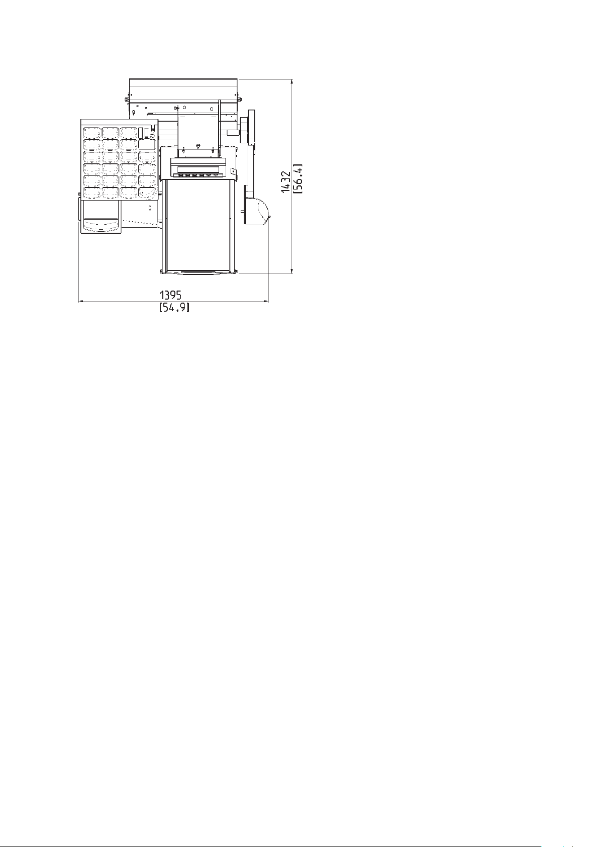
16.0 Technical data
Power supply (v):
230 volt 1 Ph 50-60 hertz
Series of concentric cones:
3 cones 43 - 115 mm
Shaft length:
7.5 “ 190 mm
Shaft diameter:
1.57 “ 40 mm
Measuring speed:
200 rpm
Balancing precision:
0.035 ounces 1 gr
Scanning device precision:
0,039" 0.1 mm
Rim width (dynamic balancing):
3 “- 20”
Rim diameter:
8 “- 30”
Overall wheel width:
21" 530 mm
Overall wheel diameter:
37" 950 mm
Maximum wheel weight:
154 lbs 70 kg
Maximum cycle time:
30 sec.
Type of data input for the DISTANCE:
Automatic, no contact with the wheel
Type of data input for the DIAMETER:
Automatic, no contact with the wheel
Type of data input for the WIDTH:
Automatic, no contact with the wheel
Dimensions of the package (mm) H x L x D:
1640 x 1420 x 1850
Dimensions (mm) H x L x D with wheel guard raised:
1700 x 1395 x 1150
Shipment weight:
350 kg
49
Page 52
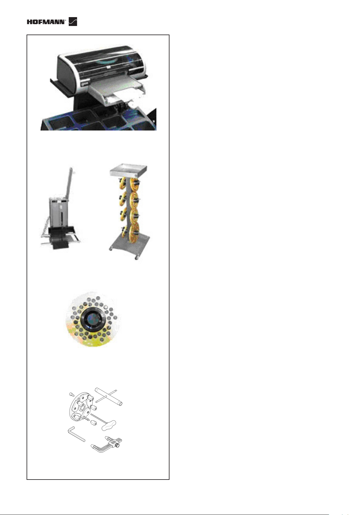
17-1
Maintenance, technical data
17.0 Accessories
17.1 Printer
The ink jet colour printer produces a professional
report that can be delivered to the client as the
balancing certificate. This certificate can function as
an extended guarantee of performance.
17.2 Wheel elevator
It can operate with a balancer, a tire changer or placed
between a balancer and a tire changer. Lifting capacity
up to 90 kg.
17.3 Trolley for Flanges
Designed for the complete range of universal and
special perforated flanges (17.4). This accessory
guarantees maximum safety in stocking.
17-2
17.4 Perforated flanges for screw
stud
A complete range of 6 universal flanges for all European
vehicles. Four flanges designed for North American
vehicles. Including bolts. Special flanges for BMW and
OPEL available. Special flange for custom-built vehicles.
17-3
17-4
17.5 SCA Flange
Adaptor for wheels with closed center hole also known
as UniLug adaptor.
When the SCA adaptor is attached to the geodyna
optima the power clamp system needs to be
switched off in the FUNCTION screen.
The operation of the geodyna optima depends a lot on
the power clamp in order to have the information
addressed to the software during some procedures. In
order not to loose the capability to know if a wheel has
been clamped or not and to keep the procedures identical
a special procedure has been implemented when the
SCA adaptor is attached to the machine.
The operator tells the machine that he clamps or
unclamp the wheel on SCA adaptor by simply
lifting the pedal in the same way as in the standard
procedure with the mid centering device.
50
17-5
geodyna optima Operator’s Manual
Page 53
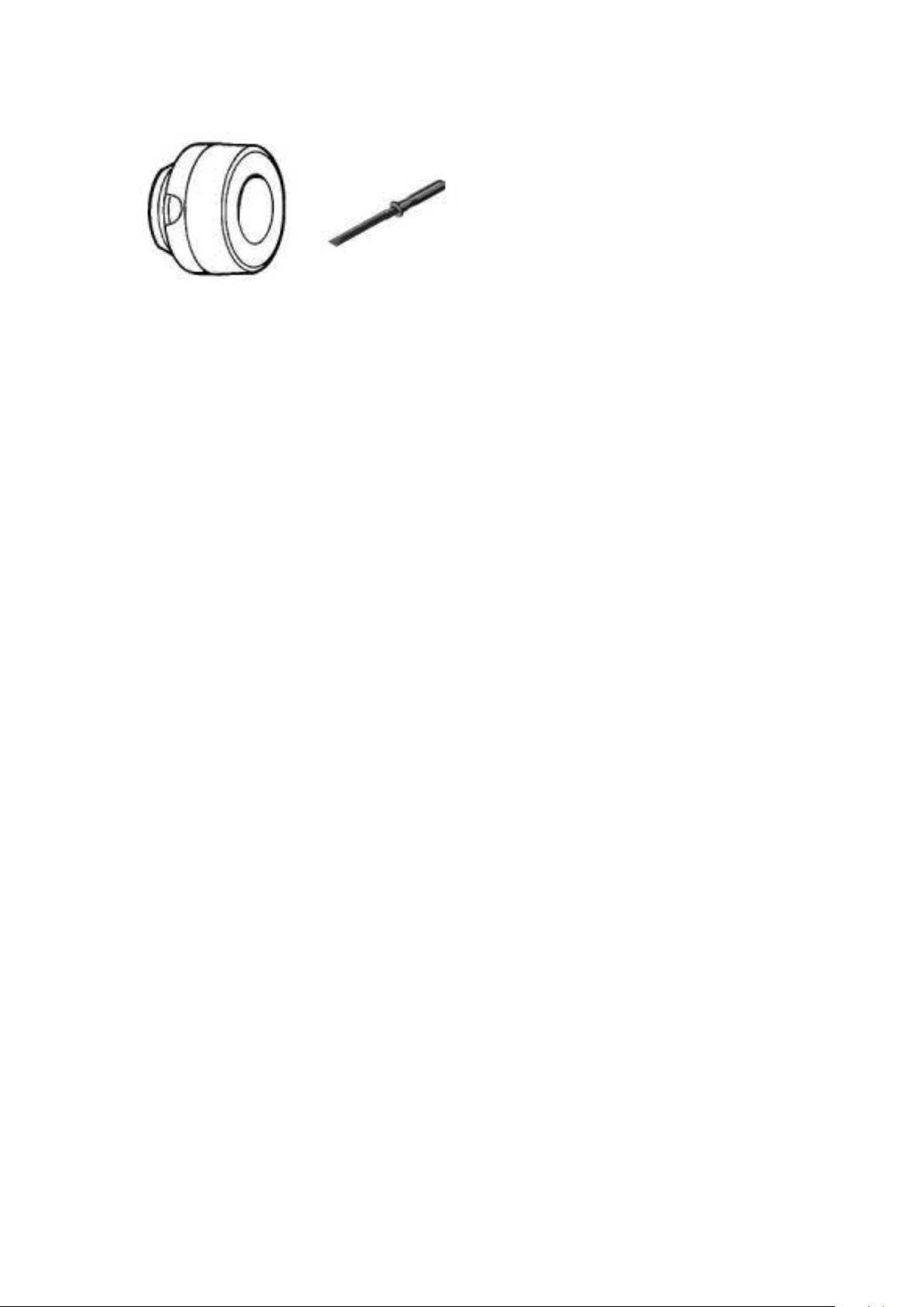
17-6
17-7
17.6 Tapered ring
A centring cone with a 5° taper, to achieve a higher
degree of wheel centring precision when fitting the wheel
on the balancer.
17.7 Wheel weight removal tool
Special tool in wear resistant plastic material, essential
for the removal of adhesive weights from alloy wheels.
Ensures that the rim surfaces are not damaged.
51
Page 54

18.0 Mise en place de la Imprimante (disponible en option)
Printer Installation Instructions (optional)
4
3
7
6x
1
(8x20)
6x
2
(6x20)
2x
(Ø 6)
2x
6
5
(Ø 8)
6
5
VELCRO
2x
geodyna optima - Operator’s Manual / Manuel d’Utilisation
52
USB
2x
EPC
MONITOR
Page 55

La página de la nota
NoteNote page
geodyna optima - Operator’s Manual / Manuel d’Utilisation
53
Page 56
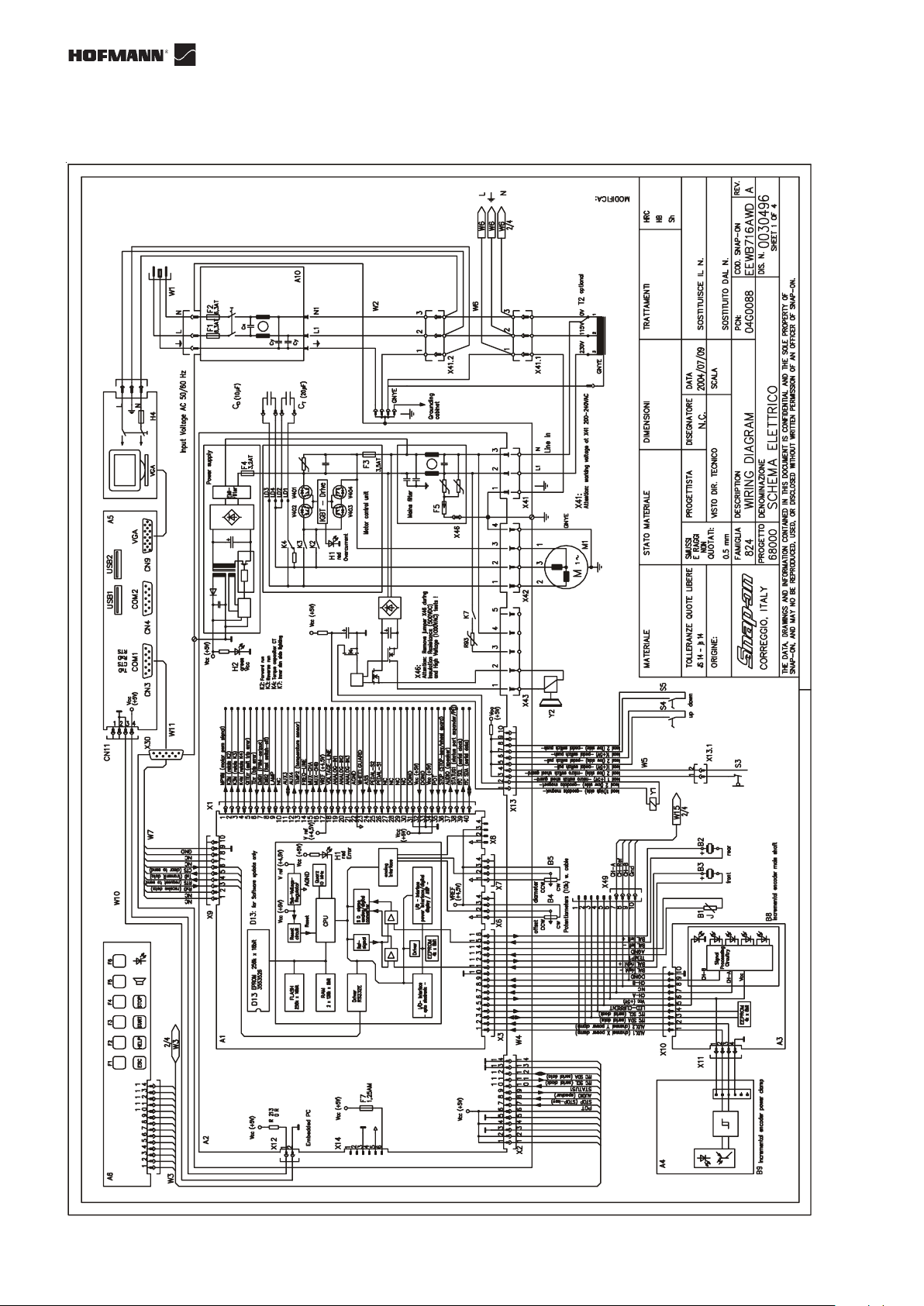
Electrical diagram
54
Page 57
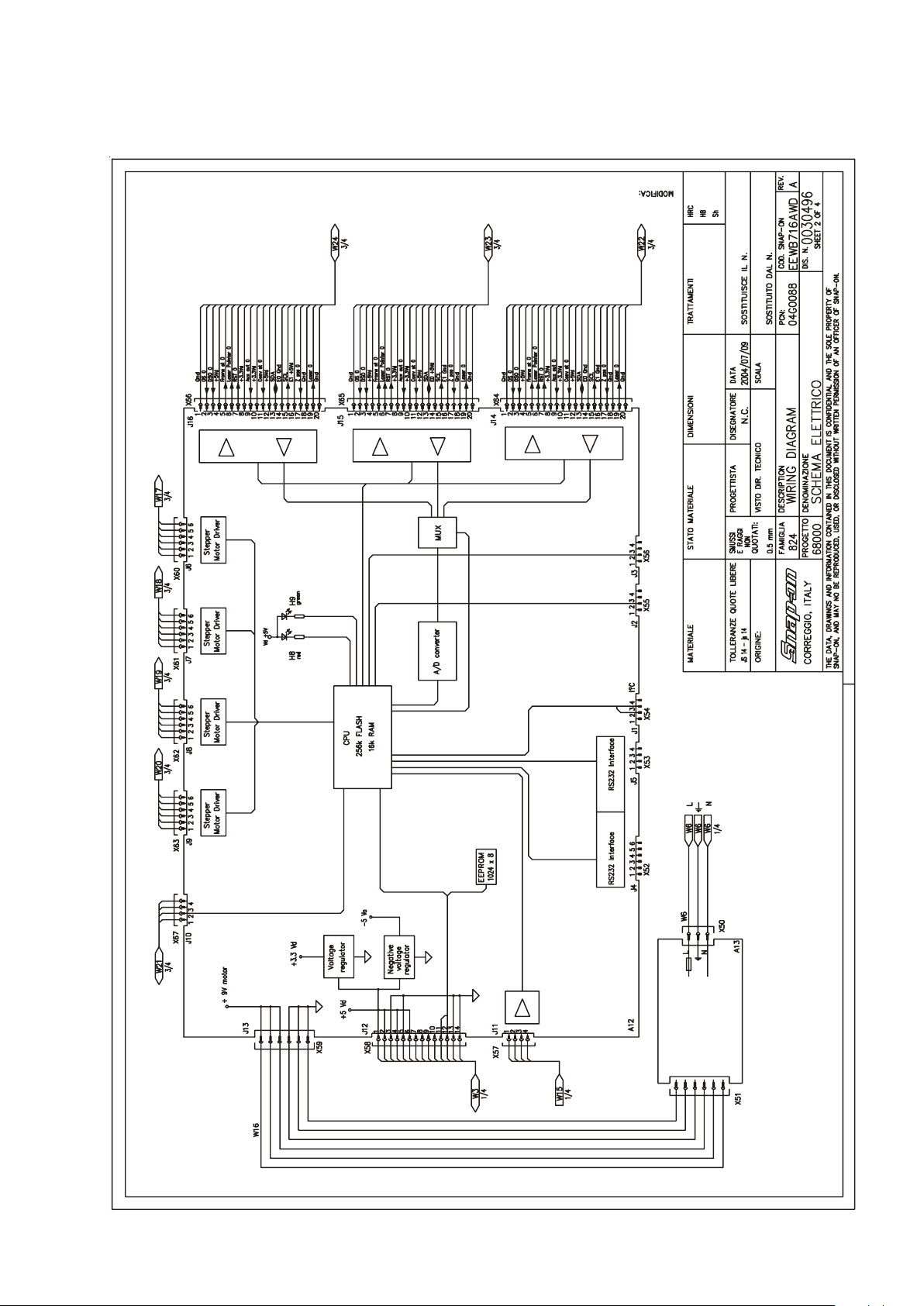
Electrical diagram
55
Page 58
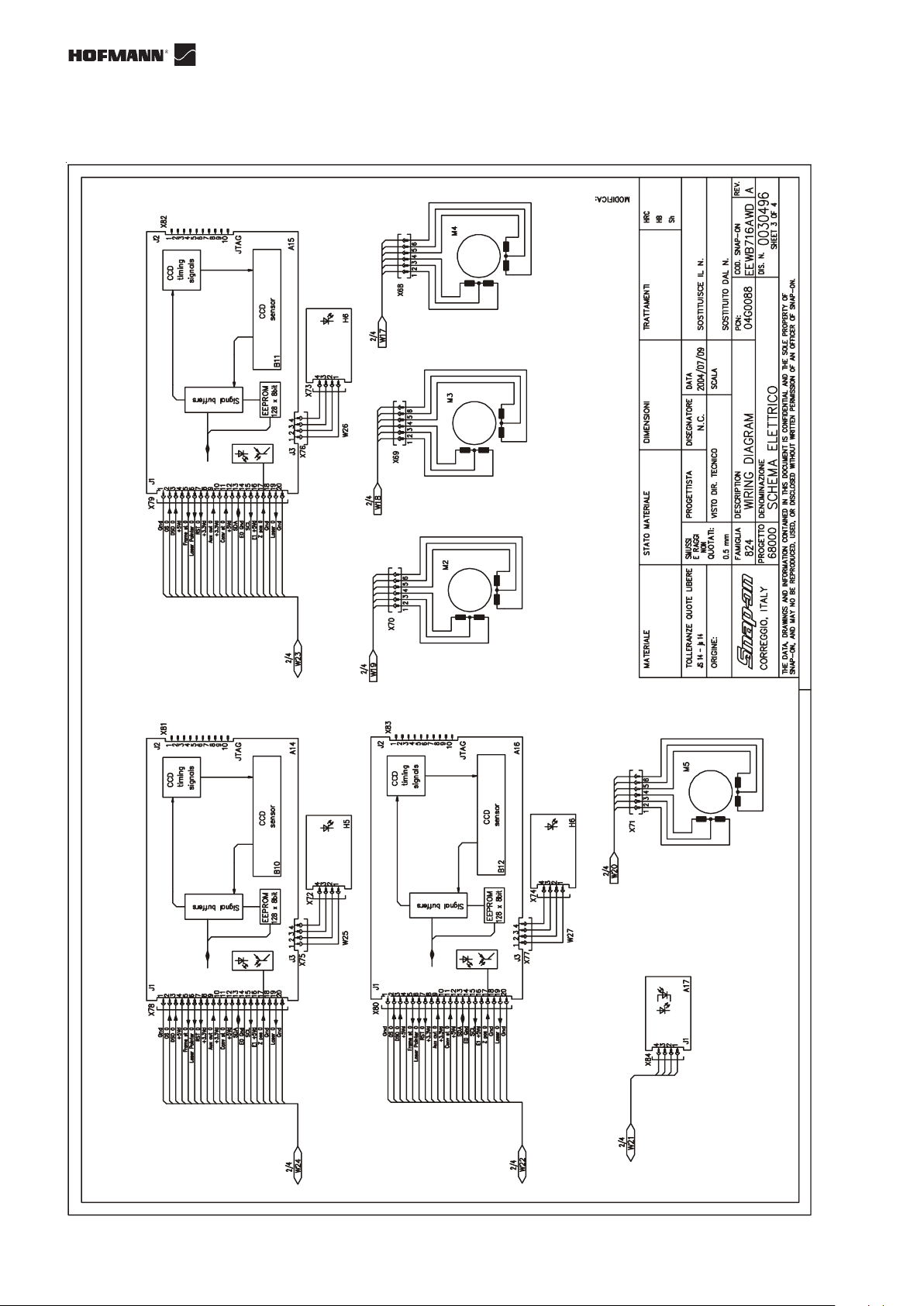
Electrical diagram
56
Page 59
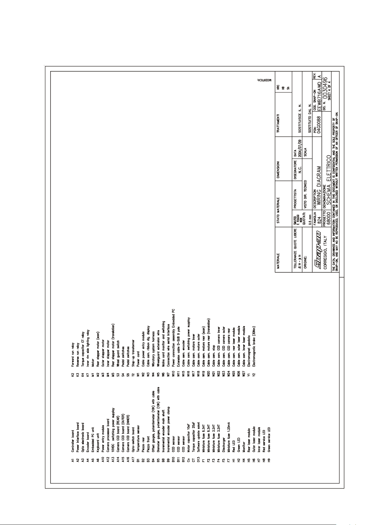
Electrical diagram
57
Page 60

Note page
MODIFIED / CHANGED PARTS Regarding Revision 02.05 (B)
List of new chapter from this revision:
At page 16-17 1.4.2 TDI Tread Dept Indication
At page 16-17 1.4.3 Print functions
At page 28-29 9.2.1 Warning Messages in Optima Entry Screen
MODIFIED / CHANGED PARTS Regarding Revision 07.05 (C)
List of new chapter from this revision:
At page 32-33 9.3 Optima Matching
At page 34-35 9.4 Rim Only diagnosis
At page 40-41 9.8 Print Report
At page 56-57 17.5 SCA Flange
At page 60-61 18 Printer Installation Instructions
UPDATING REPORT
Information added:
at Chapter 9.2
at Chapter 9.2.1
at Chapter 9.7
First edition in IT-ES-PT (the Previous Revision was available in DE-GB-FR only)
List of the changes, introduced beginning from the revision 09.05 (D)
Instruction added regarding software version 3.0
- page 20-22-24 > New Function key (F1) and (F3). Information added in (F5).
- page 26 > Position Brake Control.
- page 34 > Chapter 9.4 Rim Only Diagnosis, rewrited.
- page 38 > Chapter 9.7 Optima Parameters, point (m, n) rewrited, (n1,n2,n3,n4) added.
- page 38 > Chapter 10.1 Advanced Spoke Detection, added.
UPDATING REPORT
Raplaced/New pictures: 1.4-2 1.4-3 9.1-1 9.1-1a 9.1-2 9.1-3 9.1-4 9.1-5 F2 F3 F4 F5(9.1-6)
F5(9.1-7) F5 F6 9.2-0 9.2-1 9.2-2 9.2-3 9.2.1-1 9.2.1-2 9.3-0 9.3-1 9.3.1-2 9.3.1-3 9.3.2-0 9.41 9.4-2 9.4-3 9.4-4 9.5-0 9.6-0 9.7-0 9.7-1 9.9-1 9.9-2 10.1-1
List of the changes, introduced beginning from the revision 01.06 (E)
Additional instruction regarding software version 3.1
- page 32 > Chapter 9.3 replace the previous release chapters 9.5 and 9.6.
- page 34 > The previous release chapter 9.3 becomes chapter 9.4.
- page 36 > The previous release chapter 9.4 becomes chapter 9.5.
- page 40 > The previous release chapter 9.7 becomes chapter 9.6. Changed description from
point “m”, added description for point “n” and “n2”.
- page 38 > The previous release chapter 9.8 becomes chapter 9.7. Changed description at
UPDATING REPORT
point “a”, added description at point “b”.
- page 50 > Replaced the error messages “E360 - E361 - E362”. Added new error messages
list, from “E366”.
Raplaced/New pictures: 9.6-2, 9.6-3, 9.7-1 9.7-2
List of the changes, introduced from the revision 04.06 (F2)
Additional instruction regarding software version 3.2
- page 46 > Chapter 11.0 has been added. “Optional Functions”.
- page 48 > Chapter 11.1 has been added. “OPTI LINE Instruction”.
- page 90 > Instruction for the Error E400 has been added.
New pictures: > All the pictures of the chapters Optional Functions and OPTI LINE.
UPDATING REPORT
Page 61

Note page
Page 62

EC declaration of conformity
– Sr. No. –
EC declaration of conformity
The company
Snap-on Equipment GmbH
Geschäftsbereich Hofmann WerkstattTechnik Werner-von-Siemens-Str. 2
D – 64319 Pfungstadt
declares herewith that the
wheel balancer
geodyna optima
as designed, manufactured and put by us
on the market meets relevant basic safety
and health requirements as set forth in the
relevant EC guide-lines for machines and
electromagnetic compatibility as specified
hereafter (in their latest versions):
98/37/EC
89/336/EC
Applied harmonized and national standards:
EN 292–1, 292–2 / EN 294 / EN 349 / DIN 30 600 /
DIN 8418 / VDE 0100 / EN 5501 /
EN 50081-1 / EN 61000-6-2 / EN 61000-3-2 / EN 61000-3-3
This declaration becomes null and void if
the machine is not used as set forth under
„Scope of application” of this operation
manual, or if any modifications or changes
whatsoever are made to the machine
without prior approval from our end.
ppa.
Hans-J. Rupp
Director Sales & Service
ZEEWB716B01 12.06 cullum ENG geodyna optima.. copyright 2006 Snap-on Equipment All rights reserved
SOE Digital Code: OM-GEODYNA OPTIMA-04-06_ZEEWB716A03_RF2
 Loading...