

Page 1

Dripmaster EDD-4C
U.S. Patent No. 5,996,739 & other countries
User Guide
Document filename: Dripmaster_EDD-4C_User_Guide_18May10.doc
Important notice: Hoffmann & Hoffmann reserves the right to change this document without further notice due
to design improvements, functional modifications or quality/reliability amendments.
Copyright © 2010 Hoffmann & Hoffmann Ltd.
1
Rev. 04, May 2010
Page 2
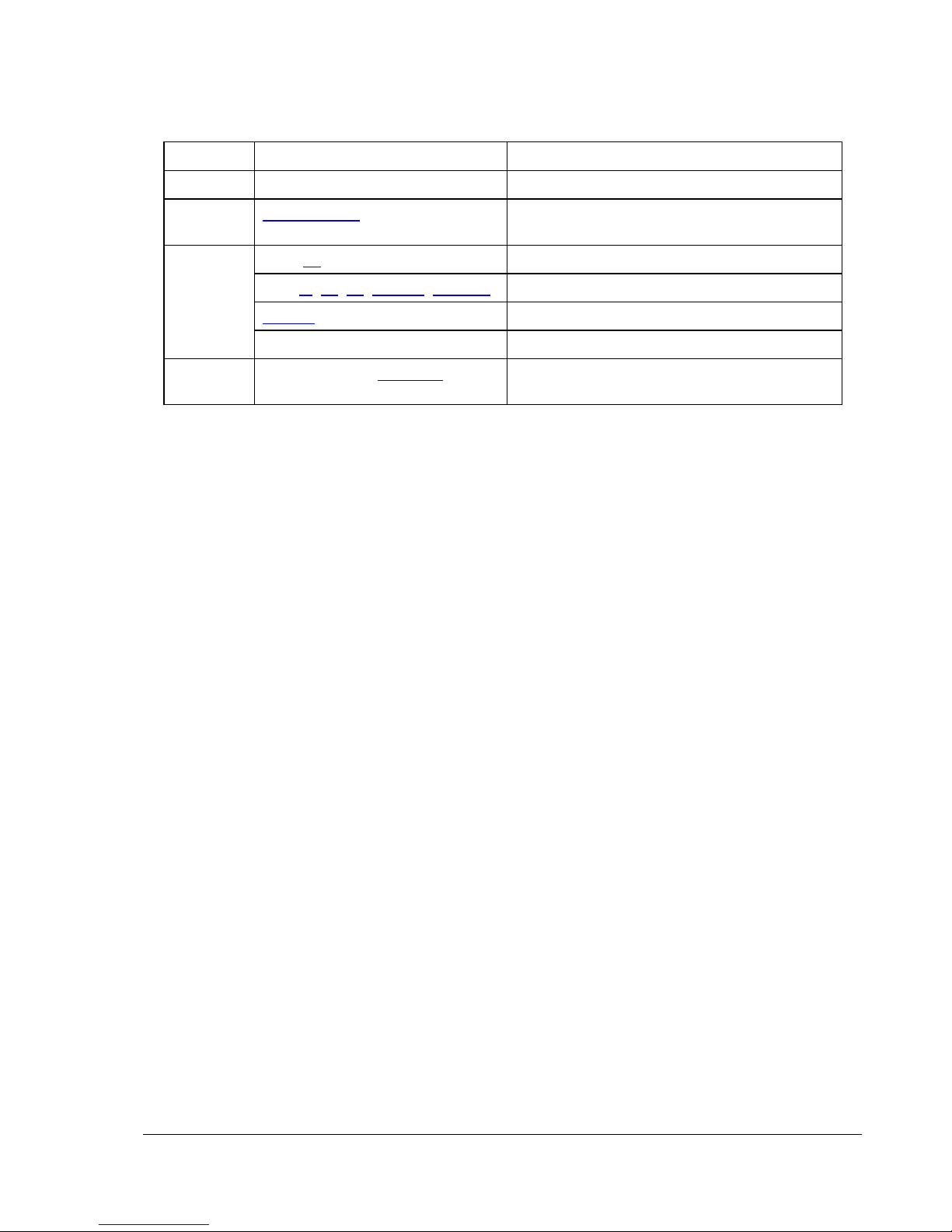
Revision History
Revision Section Notes
01 – Initial document
02 Installation Kit on page 9 Deleted ¼-inch fuel hose as part of
installation kit
03
04 Cover page and Section 7. Updated company logo and contact
Page 18 Third line of text: ...flow switch to the right...
Page 7, 10, 22, Table 1, Figure 9 Line power includes 220 VAC
Table 6 Updated specifications
Last page Updated contact information
information
2
Page 3

Contents
Section 1: Introduction ............................................................................................................................... 5
Overview ..........................................................................................................................................5
Section 2: Installation ................................................................................................................................. 7
General............................................................................................................................................. 7
Well Site Requirements.................................................................................................................... 7
Installation Kit................................................................................................................................... 9
Mounting the Dripmaster.................................................................................................................. 9
Wiring the Power and Control Cables............................................................................................ 10
Setting the Drip Rate......................................................................................................................12
Section 3: Operation ................................................................................................................................ 13
Controls and Indicators .................................................................................................................. 13
Automatic Control........................................................................................................................... 16
Setting Normal (pump on) Mode Drip Rates ....................................................................... 16
Pre-lube (pump off) Mode.................................................................................................... 17
Manual Control...............................................................................................................................17
Resetting the Dripmaster ............................................................................................................... 18
Section 4: Theory of Operation ................................................................................................................ 19
General........................................................................................................................................... 19
Search Feature .............................................................................................................................. 21
Push-Down and Push-up Features................................................................................................22
Section 5: Maintenance and Troubleshooting.......................................................................................... 23
Section 6: Specifications.......................................................................................................................... 25
Overall Dimensions ........................................................................................................................ 26
Section 7: Dripmaster Service Policy.......................................................................................................27
Installation ...................................................................................................................................... 27
Repair procedure ........................................................................................................................... 27
Product within the Warranty Period ............................................................................................... 28
Product Out-of-Warranty Period .................................................................................................... 28
Return Instructions ......................................................................................................................... 28
Terms & Conditions on reverse ..................................................................................................... 29
3
Page 4

List of Figures
Figure 1: Dripmaster EDD-4C............................................................................................................... 5
Figure 2: Installation requirements ....................................................................................................... 8
Figure 3: Dripmaster—rear view showing mounting centers................................................................ 9
Figure 4: Connection box – cable routing...........................................................................................10
Figure 5: Connection box – electrical terminals: 115 VAC unit shown............................................... 10
Figure 6: Dripmaster control panel ..................................................................................................... 13
Figure 7: Dripmaster EDD-4C Needle Valve Assembly ..................................................................... 18
Figure 8: Common Needle Valve compared to Dripmaster................................................................ 19
Figure 9: Dripmaster functional diagram ............................................................................................20
Figure 10: Dripmaster EDD-4C Needle Valve Assembly ...................................................................21
Figure 11: Dripmaster dimensions...................................................................................................... 26
List of Tables
Table 1: Connection box—power and control lines............................................................................ 11
Table 2: Pump On/Off conditions ....................................................................................................... 12
Table 3: Control panel—controls and indicators................................................................................. 13
Table 4: Routine Maintenance............................................................................................................ 23
Table 5: Troubleshooting.................................................................................................................... 23
Table 6: Dripmaster EDD-4C specifications .......................................................................................25
4
Page 5
Section 1: Introduction
Overview
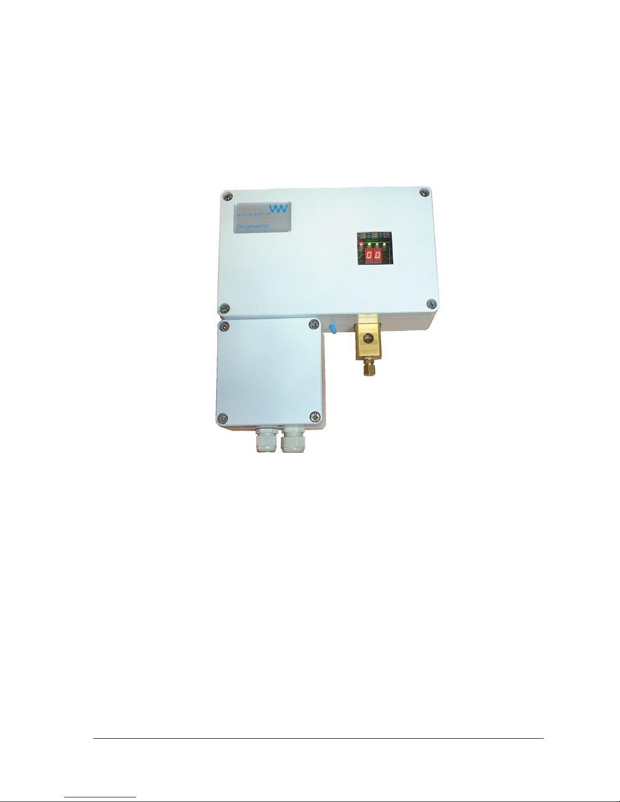
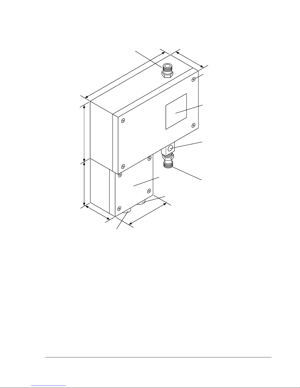
The Dripmaster is an active vertical line-shaft lubrication control and monitoring device. It
automatically stabilizes the oil drip rate so as to comply with pump manufacturer's requirements.
Figure 1: Dripmaster EDD-4C
Constant drip rate is maintained regardless of ambient temperature or hydrostatic pressure in the
feeding oil tank. This is achieved by monitoring and controlling the drip rate 55 times per hour.
There are two modes of operation:
• Normal (pump on) mode—when the well pump is operational
• Pre-lube (pump off) mode—ensures that the line-shaft is lubricated prior to turning on the well
pump.
Automatic switching between the Normal (pump on) and Pre-lube (pump off) modes is achieved by
remotely sending a control signal to the Dripmaster.
The SCADA interface provides:
• Accurate oil consumption data (drip rate count)
• Total lack of oil warning
• Automatic pump shutdown
A built-in manual mechanism ensures oil flow even in the remote possibility of unit malfunction.
5
Page 6

End of section
6
Page 7

Section 2: Installation
General
The Dripmaster installation procedure is simple and does not require any special tools, but requires
site preparation.
Well Site Requirements
• Line power (115 VAC or 220 VAC), or 24 V AC/DC must be available at the well pump.
• An eight-wire control cable (containing wires not smaller than 22 AWG) needs to be laid
between the well pump and the local PLC enclosure.
• A sturdy, vertical pole with a welded metal plate should be in close proximity to the well pump.
Note: For large oil tanks (35 to 50 gallons), mount the Dripmaster to the oil tank stand.
7
Page 8
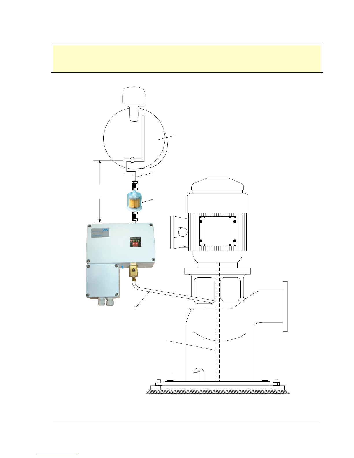
Important: The relative spacing between the oil tank, the Dripmaster, and the line-shaft inlet should be
according to Figure 2. In order to maintain minimal oil pressure on the needle valve
(especially when the oil tank is almost empty), the oil inlet should be in the range of 10 to 14
inches below the oil tank.
Oil tank
1/4-inch
(0.635 cm)
10 to 14 inches
copper pipe
(25.4 to 35.6 cm)
Oil filter
1/4-inch flexible
copper tubing
Lineshaft
Figure 2: Installation requirements
8
Page 9
Installation Kit
The Dripmaster is supplied with the following parts:
1 – oil filter (fuel filter for ¼-inch hose)
4 – mounting bolts
8 – nuts
8 – lock washers
2 – cable bushings (glands)
Make sure that all of the kit items are present. You need to obtain ¼-inch fuel hose to complete the
installation.
Mounting the Dripmaster
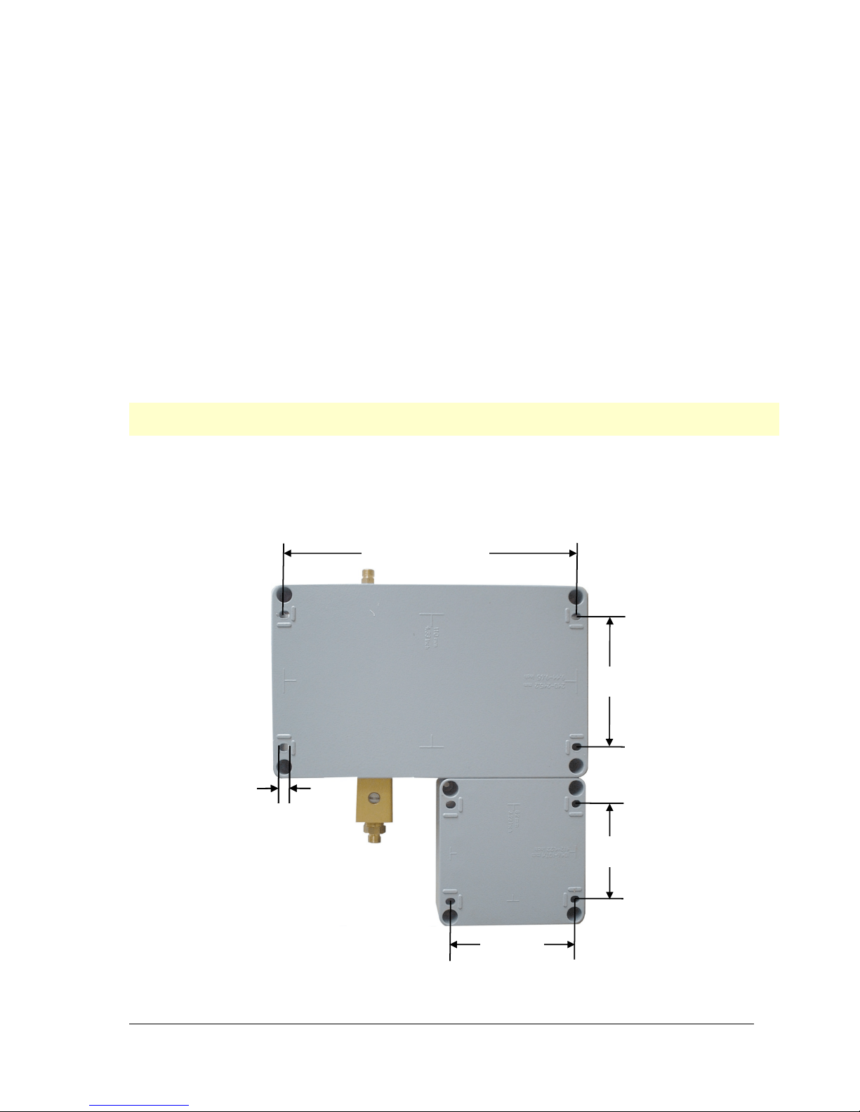
1. In order to mount the Dripmaster, drill four 1/4-inch holes in the metal plate that mounts the
Dripmaster according to the drilling template shown in Figure 3.
Note: The mounting centers for the Dripmaster are shown on the back of the unit for convenience.
Mounting the unit does not require more than four bolts.
2. Remove the Dripmaster front covers.
3. Place a bolt into a mounting hole, and keep it in place by using a nut.
4. Repeat step 3 for the other bolts.
5. Secure the device to the metal plate using the remaining nuts and lock washers.
9.55 inches (242.6 mm)
4.33 inches
(110 mm)
0.25 inches
(6.4 mm)
3.23 inches
(82 mm)
Figure 3: Dripmaster—rear view showing mounting centers
4.17 inches
(106 mm)
9
Page 10
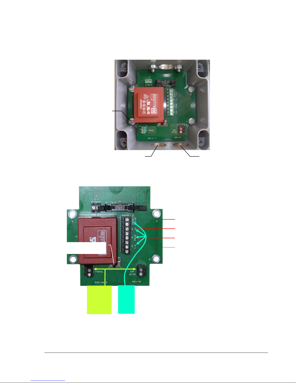
Wiring the Power and Control Cables
Power and control cables are routed through the bottom of the connection box through two strain
relief bushings.
Green ground wire
connects here
Power cable entry Control cable entry
Figure 4: Connection box – cable routing
Wire the connection box according to Figure 5. Connections are described in detail in Table 1 on
page 11.
I
I
24VAC/DC S.B. - Pre-lube (pump off) mode
J
J
LL - Total lack of oil
J
J
PULSE - Drip indication
J
Voltage selector switch SW 1:
115 VAC / 24 V AC/DC
Power
cable
115 VAC
or
24 VAC/VDC
Control
cable
J
O.K. . - Sufficient lubrication
Note: The pump can be optionally
wired to shut down when the O.K.
relay contacts open.
Figure 5: Connection box – electrical terminals: 115 VAC unit shown
1. Set the power switch SW1 located just below the transformer, for line power (115 VAC or
220 VAC) or 24 V AC/DC according to your requirements. See Figure 5.
10
Page 11

Caution: External 24 VAC power source must be
isolated from ground.
2. Route the power cable through a cable strain relief on the left side of the connection box
(Figure 4).
3. Connect the green ground wire to a chassis screw or bolt, preferably using a ring terminal. See
Figure 4.
4. Route the control cable through the right cable strain relief (Figure 4).
5. Connect control cable according to Table 1.
The connection box power and control line descriptions are shown below.
Table 1: Connection box—power and control lines
Cable or Terminal (Figure 5) LED
indicator
(Figure 6)
Power Cable (contains 3, 18 AWG
wires)
Control Cable (contains 8, 22 AWG
wires):
24VAC/DC S.B. – Pre-lube
This cable provides power to the Dripmaster. Using the
Input and output control or status signals are routed through
SB
mode
LL – Total lack of oil
PULSE – Drip indication
O.K. – Sufficient lubrication1
1
In the Pre-lube (pump off) mode, the OK contacts are always closed.
During the transition period from the 2 dpm Pre-lube mode to the preset Normal (pump on) drip rate settting (20 to 40
dpm), the OK relay is not energized (contacts open and OK LED is off) since the 15 dpm threshold has not yet been
reached. In order to signal to the SCADA room that the Dripmaster is functioning normally during this transition period
(from 2 dpm to the preset value), the OK contacts of the external time delay relay should remain closed for
approximately four minutes. In case of a total lack of oil (e.g., empty oil tank) the LL contacts close, and the OIL LED
turns on.
OIL
DRIP
OK
Function
selector switch and appropriate terminal block, for line power
(115 VAC or 220 VAC) or 24 V AC/DC can be supplied.
this cable.
When applying 24 V AC/DC to these terminals, the
Dripmaster switches to the Pre-lube (pump off) mode. The
Dripmaster rate is 2 dpm in this mode. The SB LED (item 3
in Figure 6 also lights. See page 13).
A dry contact that closes when a total lack of oil condition
occurs. The OIL LED (item 1 in Figure 6) also lights. See
page 13.
A dry contact that transmits the drip rate. The contact closes
for every drop fed to the line-shaft. The DRIP LED lights
momentarily whenever an oil drop passes through the
Dripmaster.
A dry contact that closes when sufficient oil is present. This
contact closes when the OK LED (item 2) in Figure 6 lights.
See page 13.
11
Page 12
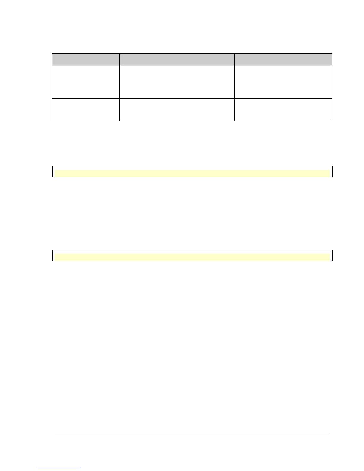
Table 2: Pump On/Off conditions
Status OK LED on OK LED off
Pump on
Pump off
• Drip rate greater than 15 dpm
• O.K. relay contacts are closed
• Drip rate is equal to or greater than 2 dpm
• O.K. relay contacts are closed
• Drip rate less than 15 dpm
• Total lack of oil (OIL LED on)
• O.K. relay contacts are open
• Total lack of oil (OIL LED on)
• O.K. relay contacts are open
6. Connect an external time-delay relay of approximately four minutes to the O.K. output. This is
necessary to extend the time needed for an OK indication during the transition from the pumpoff state to the pump-on state.
7. Connect the oil filter (supplied) to the oil tank (Figure 2).
Important: The oil filter is essential as it prevents blockage in the needle valve.
8. Connect the Dripmaster oil outlet (Figure 7 on page 18, and Figure 2) to the well shaft inlet by
means of flexible ¼-inch copper tubing.
Setting the Drip Rate
1. Set the dip switch settings for the Normal (pump on) mode using the drip rate setting toggle
switches. (see Setting Normal (pump on) Mode on page 16).
Note: There are 50 drops per 1 cc, and there are 3785.4 cc per gallon.
2. Replace both covers and tighten the eight cover screws so that the unit is watertight.
12
Page 13
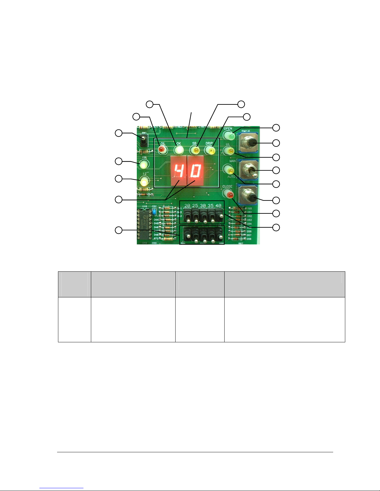
Section 3: Operation
Controls and Indicators
Button and indicator locations on the Dripmaster control panel are shown below.
Presence of oil
Lack of oil
Display switch
Freeze
12-second timer
Drip rate display
Timing toggle
11
1717
1616
1515
1414
1313
Dripmaster window
22
area
switches
Figure 6: Dripmaster control panel
Table 3: Control panel—controls and indicators
Item
number
(Figure 6)
Name Control or
Indicator
Function
Pre-lube (pump off) mode
33
Drip rate
44
Valve opening
55
66
Open Valve
77
Valve fully open
Control Mode
88
99
Manual Operation
Close Valve
1010
1111
Valve Closing
Drip Rate toggle
1212
switches
1
Oil
Red LED Lights if the valve is completely closed,
indicating a complete absence of oil.
A corresponding relay contact closes when
this LED is on. The terminal for this contact is
called LL (Lower Limit) and appears in Figure
5 on page 10.
13
Page 14
Item
number
(Figure 6)
Name Control or
Indicator
Function
2
OK
Green LED Indicates that sufficient oil is delivered
whether the well pump is on or off.
In the Normal (pump on) mode, this
corresponds to oil drip rates in excess of 15
dpm.
In the Pre-lube (pump off) mode, the LED
lights when the rate is between 1 and 15
dpm. The LED is off when a total lack of oil
condition occurs, and the OIL LED lights.
A corresponding relay contact closes when
the OK LED is on. The terminal for this
contact is called O.K. and appears in Figure 5
on page 10. This terminal can be used to
directly turn off the well pump in the Normal
(pump on) mode, when drip rates are less
than 15 dpm.
3
SB
Yellow LED Lights in the Pre-lube (pump off) mode when
24 V AC/DC is applied to the S.B. terminals in
the connection box. The drip rate in this mode
is always 2 dpm.
4
DRIP
Yellow LED This LED flashes whenever a drop passes
the photoelectric sensors in the Dripmaster
needle valve assembly (see Figure 10 on
page 21). In the Pre-lube (pump off) mode,
the DRIP LED flashes approximately every 30
seconds, indicating that oil is flowing to the
lineshaft at a 2 dpm rate.
5
6
OPEN
SW16
Green LED Lights when the motor is opening the valve.
Push button
Press to manually open the valve—for
troubleshooting, and can be used to shorten
the time to reach the preset drip rate.
7
8
UL
SW17
Yellow LED Lights when the valve is completely open.
Toggle switch Select between manual and automatic
operation:
• Manual (MAN)
• Automatic (AUTO)
9 Manual Mode Yellow LED Lights in the manual mode—when the mode
switch
(item 8) is in the up position
10
SW18
Push button
Press to manually close the valve—for
troubleshooting, and can be used to shorten
the time to reach the preset drip rate.
11
CLOSE
Red LED Lights when the motor is closing the valve.
14
Page 15

Item
number
(Figure 6)
12 Drip Rate Toggle switches Sets the drip rate for the pump-on mode.
13 Timing Toggle switches These switches are set according to the
Name Control or
Indicator
Function
Choose only one toggle switch, and push it
up to the desired dpm value.
section "Setting Normal (pump on) Mode Drip
Rates", starting on page 16.
14 Drip rate 7-segment
Display
15
16
17 Display switch Toggle switch Controls the two-digit numerical display:
12 ' '
FR
Yellow LED Flashes every 12 seconds for timing
Green LED Lights to indicate the six-second freeze
A two-digit display shows the drip rate count
purposes. You can count the number of drips
seen during this 12-second interval and
multiply them by five to arrive at the dpm rate.
This LED is useful when you want to quickly
stabilize the drip rate by pressing the Open
Valve (SW16) or Close Valve (SW18) push
button.
interval. During this interval, which occurs
once per minute, the needle valve may be
opened or closed in order to adjust the drip
rate.
• In the down position (recommended):
When pump is on, displays the last minute
drip count for a period of six seconds. The
display goes off until the next minute drip
count is displayed. When the pump is off,
the display remains off.
• In the up position (used for factory tests
only).
15
Page 16
Automatic Control
When the Control Mode toggle switch SW17 is in the lower AUTO position (item 8 in Figure 6), the
Dripmaster automatically stabilizes the preset drip rate. At the end of each 60 second interval, a
short correction command is given only if there is a deviation from the desired preset drip rate.
The valve closes if the actual drip rate is 2 drips/minute or more than the preset value.
The valve opens if the actual drip rate is 1 drip/minute less than the preset value.
Setting Normal (pump on) Mode Drip Rates
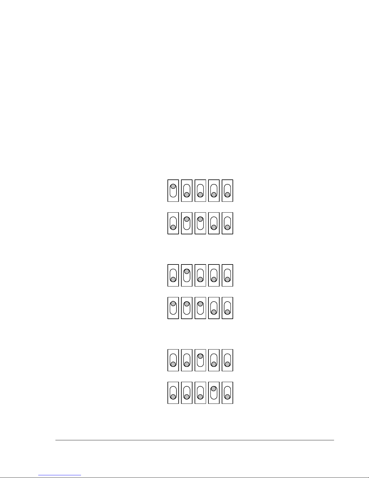
During normal operation (when the well pump is operating), the drip rate is selectable for drip rates
of 20, 25, 30, 35, or 40 drips/minute (Figure 6).
The toggle switch positions for each drip rate are shown below.
20 dpm toggle switch setting
20 25 30 35 40
124810
25 dpm toggle switch setting
30 dpm toggle switch setting
20 25 30 35 40
124810
20 25 30 35 40
124810
16
Page 17
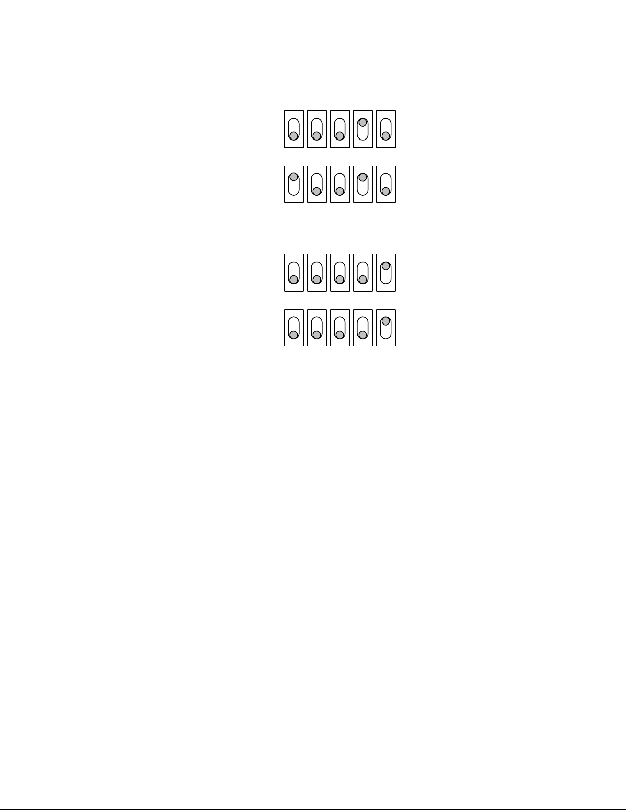
35 dpm toggle switch setting
20 25 30 35 40
124810
40 dpm toggle switch setting
20 25 30 35 40
124810
The OPEN and CLOSE LEDs indicate whether the needle valve is opening or closing. See items 5
and 11 in Figure 6 on page 13.
Pre-lube (pump off) Mode
To select the Pre-lube mode, 24 V AC/DC must be applied to the S.B. terminals in the connection
box (Figure 5). In this mode, the drip rate is automatically set to 2 dpm.
Manual Control
This mode permits emergency operation in the rare case when there is a suspected failure of the
main circuitry.
Select the manual mode by switching the Mode toggle switch to the upper MAN position (Figure 6).
This mode bypasses the electronic control circuitry, and allows the operator to modify the drip rate
by using the Open Valve (manual) and Close Valve (manual) push buttons.
Use the Drip verification peephole (see Figure 7 below) to check the drip rate.
In this mode, power is removed from the circuitry, except for the push buttons, motor, and Manual
mode LED.
17
Page 18
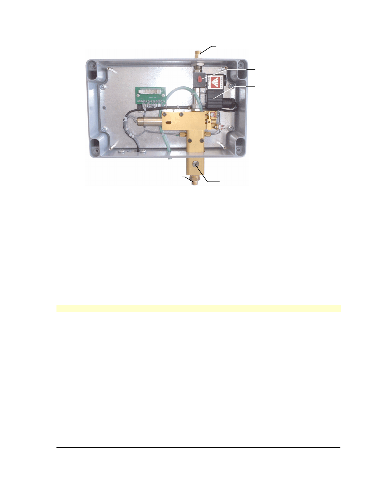
Oil inlet
Manual oil flow switch
Internal solenoid
Oil outlet
Drip verification peephole
Figure 7: Dripmaster EDD-4C Needle Valve Assembly
The internal solenoid is powered by the Dripmaster power source. When powered up, the solenoid
allows oil flow. When powered down, the solenoid blocks oil flow.
To allow oil flow when the Dripmaster is not powered on, turn the manual oil flow switch to the right
90 degrees.
Resetting the Dripmaster
There are two ways to reset the Dripmaster:
1. By disconnecting the power source to the Dripmaster for 10 seconds, and then reconnecting it.
2. By removing the Dripmaster cover, and raising the Control Mode toggle switch to the MAN
position, and then back to the AUTO position.
In both cases, the circuit voltage is interrupted and then restored.
Note: In case (2) above, a random drip rate is displayed initially which can be ignored.
18
Page 19
Section 4: Theory of Operation
General
The Dripmaster is a gravity-based oil lubrication system.
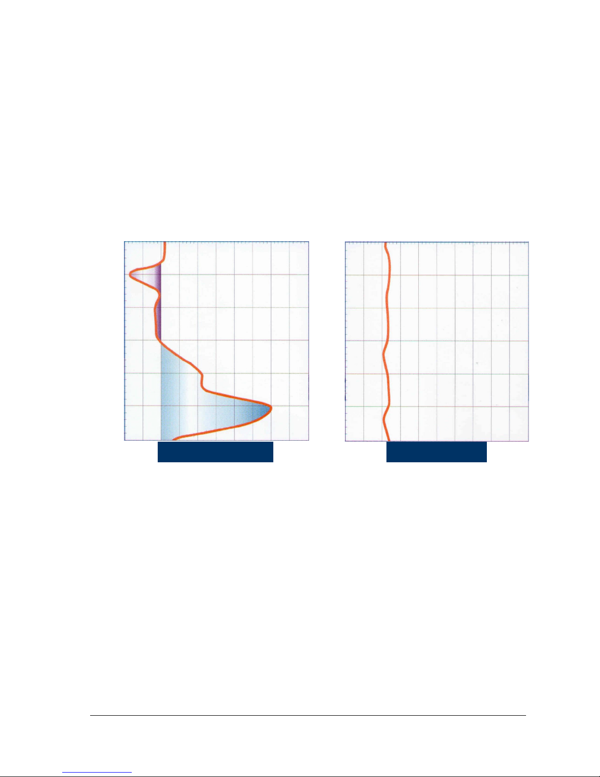
The common needle valve fed from an oil tank does not provide any regulation of the drip rate—the
rate varies in response to variations in temperature (day versus night and time of year) and changes
in the tank oil level (hydrostatic pressure). Another cause of rate fluctuation is temporary valve
blockage.
The Dripmaster performs as an automatic needle valve that regulates oil flow (Figure 8).
Drops per minute Drops per minute
0
200180160140120100806040200 200180160140120100806040200
0
2
4
6
8
Elapsed time (hours)
10
12
2
4
6
Elapsed time (hours)
8
10
12
Needle Valve Dripper Dripmaster
Figure 8: Common Needle Valve compared to Dripmaster
The components that make this possible are described below.
The servo motor regulates the needle valve aperture according to the preset drip rate value. A
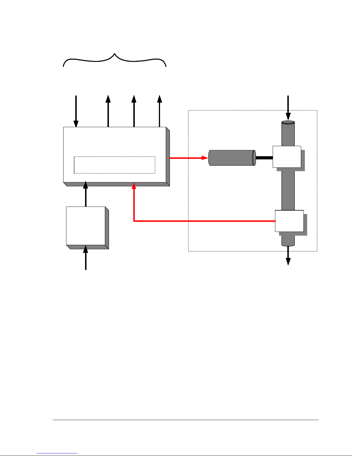
photoelectric sensor detects the drips and reports the drip count to the control circuitry. The control
circuitry sets the mode of operation and generates the alarms and drip count information to the
SCADA interface.
The Dripmaster EDD-4C incorporates a specially-designed needle valve connected to a servo
motor which automatically compensates for rate fluctuations. The compensation magnitude is
defined by the control circuitry. For example, if the drip rate set point is 40 drips/minute, and the drip
rate drops below that level for any reason, the servo motor that attaches to the needle valve opens
it to increase the drip rate to maintain 40 drips/minute. Conversely, if the drip rate exceeds the set
point, the servo motor closes the needle valve to maintain the set point value (Figure 9).
19
Page 20
To SCADA Interface
Normal
Modes
/
Pre-lube
Drop
Pulses
O.K.
state
Control Circuitry
Preset Selectors & Display
Power
Supply
Lack of
Oil
Mechanical Stage
Servo
Motor
Oil Inlet
from Reservoir
Needle
Valve
Optic
Drop
Detector
Line voltage
(115V or 230 V)
or 24V Feed
Oil Outlet to Shaft
Figure 9: Dripmaster functional diagram
A two-digit display is visible in the Dripmaster display window (see Figure 6 on page 13)—this is a
drip counter that freezes for six seconds for each one minute interval and indicates the number of
drips applied during the previous minute (Freeze mode).
During the freeze period, the servo motor is actuated to compensate for drip rate deviations.
A built-in fail-safe relay (O.K. relay) is energized when the drip rate exceeds fifteen drips per minute
in the Normal (pump on)l mode. External dry relay contacts permit direct control, such as pump
shut-off. Other dry contacts in the Dripmaster are available to transmit the drip rate, and for warning
of a total lack of oil condition.
The Dripmaster EDD-4C contains two drip rate settings, depending on the mode of operation:
• Normal (pump on) mode—the following values are selectable:
• 20, 25, 30, 35, or 40 drips/minute
• Pre-lube (pump off) mode—in this mode, the drip rate is automatically set to 2 dpm.
20
Page 21
A built-in, SCADA-compatible report-back mechanism provides the status and alarm information.
This information is sent to the local PLC on site. The following signals are reported:
• OK state – signals that the oil drip rate exceeds a factory-set threshold. Whenever the oil drip
rate falls below this threshold, the OK state is disabled and a relay contact can turn off the well
pump directly or signal the SCADA room, which in turn can shut down the pump.
• Drip rate count– transmits the oil drip rate to the SCADA room, thereby providing the data to
calculate oil consumption.
• Lack of oil alarm – the Dripmaster detects and warns of a lack of lubrication, as a result of an
empty oil tank or blockage in the oil inlet or outlet.
Manual operation is possible using the OPEN and CLOSE push buttons on the control panel. The
built-in peephole allows the operator to count the drips per minute.
Switching between the Pre-lube (pump off) mode and Normal (pump on) mode is accomplished by
applying or removing a 24 V AC/DC voltage to the S.B. terminals in the connection box. Applying a
24 V AC/DC voltage sets the Dripmaster to the Pre-lube mode of operation. Removing the 24 V
AC/DC voltage causes the Dripmaster to switch to the Normal (pump on) mode.
Search Feature
In exceptional cases, where only a few drops are counted, or none at all, the drip search function is
activated. This situation occurs if there is needle valve blockage or when there is a continuous flow
of oil. In the continuous flow case, there are no individual drops and consequently no counter
readings. Continuous oil flow may occur when filling an almost empty oil tank, for example. In case
of partial blockage, the drip search function scans until drops appear (the needle valve opens
continuously until drops are detected). If no drops are detected during the drip search (if the oil
blockage or continuous oil flow persists), then the needle valve eventually reaches its upper limit,
the UL LED illuminates briefly, and the motor changes its direction of rotation and starts to close the
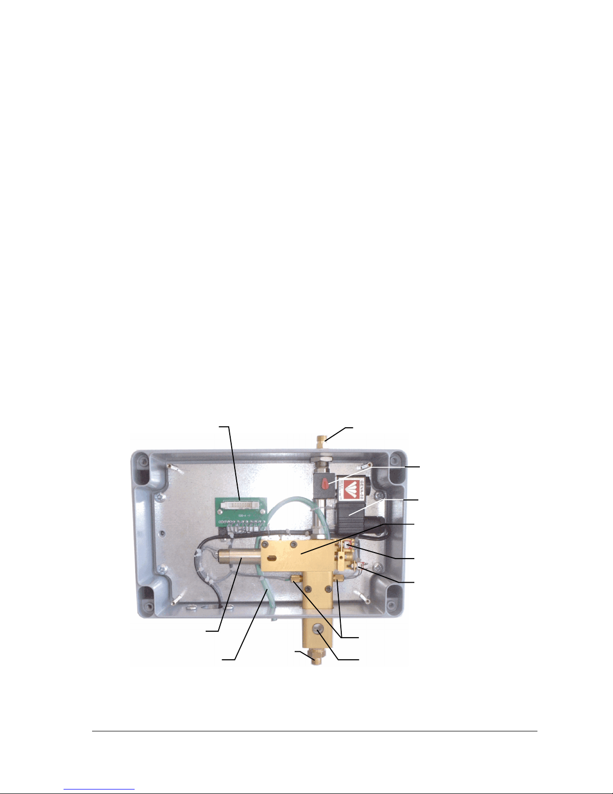
needle valve (Figure 10).
Control circuitry
interface
Servo motor
Overflow/vent hose
Oil outlet
Oil inlet
Manual oil flow switch
Internal solenoid
Needle valve assembly
Lower Limit switch
Upper Limit switch
Photoelectric sensor
Drip verification peephole
Figure 10: Dripmaster EDD-4C Needle Valve Assembly
When and if oil drops are detected, the search function stops, and normal stabilization resumes. If
no drops are detected while the needle valve is closing, then the needle valve eventually reaches its
21
Page 22

lower limit and the OIL LED lights continuously. The LL relay outlet contact closes, transmitting a
total lack of oil condition. At this stage, there is no vertical line-shaft lubrication which means that
either the oil tank is empty or there is an oil flow blockage between the oil tank outlet and the
Dripmaster inlet.
In the case of oil flow blockage in the Dripmaster outlet pipe, excess oil briefly flows from a built-in
overflow hose (see Figure 10 above). Also, the OIL LED turns on, and oil flow is cut off by the
closure of the needle valve. After taking corrective measures, you must reset the system. See
"Resetting the Dripmaster" on page 18.
The internal solenoid provides instantaneous on/off control of oil flow. Whenever the system power
(115 VAC, 220 VAC, or 24 V AC/DC) is on, the energized solenoid allows oil flow. Oil flow stops
when the system power ceases. The oil flow can be manually opened or closed via the manual oil
flow switch (Figure 10).
Push-Down and Push-up Features
In order to enhance the response time of the system whenever the drip rate exceeds 80 dpm, an
automatic push-down mechanism is engaged. This is achieved by continuously closing the valve for
a number of seconds. Excessive drip rates may occur when filling an empty oil tank, or when the
Dripmaster has finished scanning.
Similarly, an automatic push-up mechanism accelerates the stabilization of the system whenever
the Dripmaster is transferred from the Pre-lube (pump off) mode to the Normal (pump on) mode.
This mode change occurs when the 24 V AC/DC is removed from the S.B. terminals in the
connection box.
22
Page 23
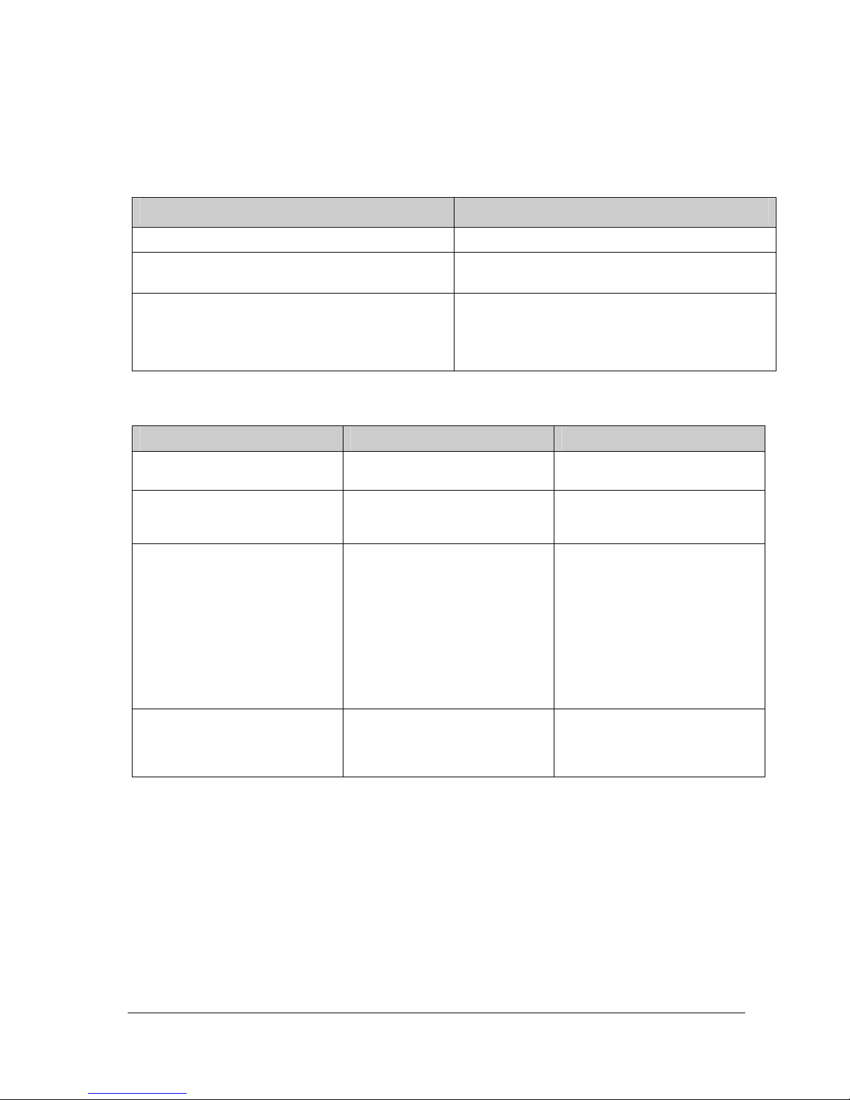
Section 5: Maintenance and Troubleshooting
Table 4: Routine Maintenance
Task Frequency
Check for oil leaks Monthly
Oil filter change (the oil filter used can be an
Every six months
automotive fuel filter with ¼" fittings)
Check for normal operation
• The displayed drip rate is equal to the Normal (pump
on) mode drip rate setting, within a -1, +2 digit
tolerance
Weekly
Table 5: Troubleshooting
Problem Possible Cause Solution
The display and LEDs are not lit.
An unusual result appears on the
display
You want to quickly stabilize the
Dripmaster for a new drip rate
A suspected fault has occurred in
the system; the drip rate is much
higher or lower than expected.
• The unit is not powered. • Check power in the connection
box.
• Changing the mode toggle
switch (item 8 in Figure 6 on
page 13).
• You just refilled the oil tank.
• You just increased the drip rate
setting in the Normal (pump on)
mode.
• Circuit failure
• Ignore.
• With the Mode toggle switch
(item 2 in Figure 6 on page 13)
in automatic (AUTO), hold
down the Close push button
momentarily to slow down the
drip rate.
• With the Mode toggle switch in
position AUTO, hold down the
Open push button momentarily
to speed up the drip rate.
• Set the Mode switch to MAN,
and set the drip rate manually
using the Open and Close
push buttons. See Figure 6.
23
Page 24

Problem Possible Cause Solution
The OIL LED is on.
• Oil tank is empty
• A shut-off valve at the outlet of
the oil tank might be closed
• Oil flow from the oil tank may be
obstructed; the oil filter may be
clogged
• Oil blockage between the
Dripmaster outlet pipe and the
line-shaft—excessive oil briefly
flows from a built-in overflow
hose
• Refill the oil tank
• Open the shut-off valve
• Change the oil filter, or clean out
any obstructions in the pipe
between the oil tank and the
Dripmaster inlet
• Clean out any obstructions in
the pipe between the
Dripmaster outlet and the lineshaft.
Note: Reset the system after fixing
the problem. See Resetting
the Dripmaster on page 18.
After restoration, the
counter displays 00, and the
drip search function causes
the motor to open the
needle valve until drops are
detected, after which normal
stabilization occurs.
24
Page 25
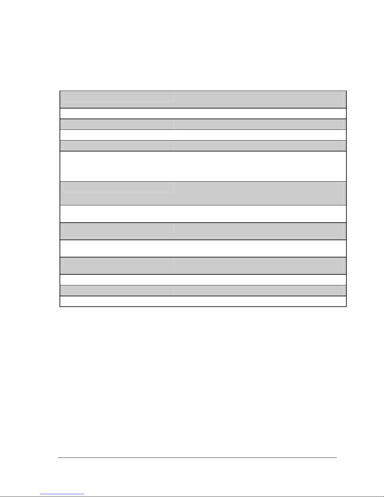
Section 6: Specifications
Table 6: Dripmaster EDD-4C specifications
Power requirements 115 VAC, 10 VA, or 24 V AC/DC
220 VAC, 10 VA or 24 V AC/DC
Normal (pump on) mode preset drip rates 20, 25, 30, 35, 40 dpm
Pre-lube (pump off) mode drip rate 2 dpm
Drip volume 50 drops per 1 cc
PULSE relay contact 35 VDC – 0.5 A
O.K. relay contact 250 VAC – 10 A AC1
110 VAC – 10 A AC1
110 VDC – 0.3 A
30 VDC – 10 A
L.L. (low oil level) relay contact 125 VAC – 0.5 A
110 VDC – 0.2 A
24 VDC – 1 A
S.B. terminals (Normal/Pre-lube mode
control)
Duty cycle 60 seconds counting
Drip stabilizing tolerance From (x-1) to (x+2) dpm
Oil on/off solenoid 24 VDC
Oil inlet/outlet Male thread ¼-inch BSP
Dimensions (W x H x D) 10.35 x 11.3 x 3.58 inches (263 x 287 x 91 mm)
Weight (approximate) 11 lbs (5 kg)
All specifications shown are subject to change.
24 V AC/DC
6 second Freeze
(where x is the pre-selected drip rate)
24 VAC (optional)
25
Page 26
Overall Dimensions
(16.2 cm)
6.38 inches
(12.5 cm)
4.92 inches
3
.
1
9
i
n
(
c
8
.
1
c
m
)
1/4 inch BSP
0
1
h
e
s
Oil inlet
c
n
i
5
3
.
3
.
6
2
(
3
.
5
8
i
n
(
c
9
h
.
1
e
s
c
m
s
e
h
)
m
c
Connection
box
Control cable entry
s
e
h
c
n
)
i
m
8
c
8
.
4
4
.
2
1
(
)
1/4-inch screws
(8 places)
Display window
Drip verification
peephole
Oil outlet
1/4 inch BSP
Power cable entry
Figure 11: Dripmaster dimensions
The Dripmaster enclosure is made of painted, cast aluminum.
26
Page 27

Section 7: Dripmaster Service Policy
This policy has been established to cover the servicing of Hoffmann & Hoffmann products,
regardless if it is within or beyond the warranty period.
Installation
1. The installation services required for the Dripmaster includes the following:
a. Infrastructure (trench digging, cable laying)
b. Oil tank stand
c. Dripmaster mount
d. Cabling (4 pairs)
e. 24V power source
f. Testing
2. Hoffmann & Hoffmann's representative or its authorized subcontractors will perform the
installation work required and charge the customer directly.
3. In cases where there is a prior approval by Hoffmann & Hoffmann, the customer may do the
installation.
4. The representative will assume full responsibility for the installation work he performs.
Repair procedure
1. In case of a default, the customer can follow the Troubleshooting table (Table 5 on page 23) to
try and solve the problem.
2. If the customer does not succeed in solving the problem, he can fax or email Hoffmann &
Hoffmann's local representative, describing the problem based on the Troubleshooting table
(Table 5 on page 23), and indicating which of the procedures failed ("the notice"). This should
be directed to the local representative where he has a service agreement.
3. Hoffmann & Hoffmann's representative will respond within two working days.
4. The problem might be fixed by the representative in one or more of the following ways:
a. Remotely: instruct the customer on how to solve the problem by phone.
b. On Site: technician arrives at the customer’s site to perform first level support (basic
repairs and parts replacements).
c. In Hoffmann & Hoffmann lab: ship the unit to Hoffmann & Hoffmann’s Chicago office.
5. The representative should first try to solve the problem remotely.
6. In case the problem is not solved remotely, the representative will send a technician to solve the
problem on site, within two working days.
7. If the representative concludes that the problem can only be solved in Hoffmann & Hoffmann's
lab, he should disconnect the unit and ship it to Hoffmann & Hoffmann's Chicago office.
8. The representative has the option to replace the faulty unit with one of his spare units.
9. The repaired unit should be shipped back from Hoffmann & Hoffmann to the representative.
10. The representative will send the repaired unit, with the repair invoice and shipment cost, to the
customer.
27
Page 28

Product within the Warranty Period
1. All Hoffmann & Hoffmann products have a one year limited warranty.
2. Hoffmann & Hoffmann Warranty will apply only to units installed by authorized Rep/Distributors
or by the customer (if Hoffmann & Hoffmann authorized installation by the customer).
3. Hoffmann & Hoffmann is not responsible for damages caused by extreme environmental
factors, i.e. temperature extremes.
4. If the failure occurred during the Warranty Period, Hoffmann & Hoffmann will cover the repair
cost. The customer will only pay for the shipment to the nearest Hoffmann & Hoffmann office.
Product Out-of-Warranty Period
1. If product is not under warranty, the customer will be responsible for all of the repair cost as per
his agreement with the representative including:
• Technician labor cost
• Spare parts cost
• Other expenses (travel, shipment)
2. Repairs at Hoffmann & Hoffmann lab: if the product arriving to the lab is out of the Warranty
Period or if failure is deemed by the factory to have been caused by abuse or tampering, the
following procedure applies:
a. Diagnosis will be made and repair completed, providing the repair charges are less than
500 USD.
b. We will diagnose (but not repair) a returned unit and notify by email or by fax the estimated
charges if any of the following apply:
i. Repair charges exceed $500.
ii. You specifically requested an estimate of required repairs and charges.
iii. When the product is over 7 years old. Hoffmann & Hoffmann takes pride in attempting
to repair products of any age. However, due to component availability and product
improvements, some older products may no longer be repairable.
c. When you receive an estimate and would like us to proceed, please mail or fax one signed
copy (with P.O. number if required) or phone or email your authorization.
d. Note: Un-repaired items are discarded unless you wish them to be returned to you. There
is currently a $150 charge plus shipping per un-repaired item to cover diagnosis and
handling such returns. Items remaining more than 90 days from estimate date will be
discarded.
e. Service warranty period is ninety days for all repaired/replaced parts.
Return Instructions
1. When sending your product for repair, please include the following information:
a. Company name and address
b. Contact name
c. Phone, fax and/or email
d. Description of the problem(s)
28
Page 29

2. Return properly packaged item to the address of your local Rep/Distributor or to Hoffmann &
Hoffmann lab.
3. This warranty is limited to the repair or replacement of the Hoffmann & Hoffmann products only.
Hoffmann & Hoffmann assumes no other responsibility or liability.
4. Hoffmann & Hoffmann reserves the right to make changes in policy and pricing without notice.
Terms & Conditions on reverse
The purchaser agrees to the following terms and conditions:
1. Shipping:
a. If not specified, goods will be shipped by the most economical carrier of our choice.
Domestic orders will be shipped GROUND unless specified. International orders will be
shipped AIR unless specified.
b. To obtain warranty service, you must deliver the product in either its original packaging or
packaging affording an equal degree of protection.
2. Insurance: Insurance costs will be added to all invoices.
3. F.O.B.: Free On Board. ALL goods are shipped F.O.B. All shipping and insurance costs, local
and/or foreign taxes or exportation / importation duties are the responsibility of the customer.
4. Claims: Claims for damage sustained in transit should be made promptly to your carrier.
5. Force Majeure: Hoffmann & Hoffmann shall not be liable for any delay in or impairment of
performance resulting in whole or part from acts of nature, labor disruptions, shortages, inability
to procure product, supplies or raw materials, severe weather conditions, or any other
circumstances or cause beyond the control of Hoffmann & Hoffmann in the conduct of its
business.
Corporate office:
Hoffmann & Hoffmann Ltd., 7 Shoham St., P.O.Box 7544, Petach Tikva 49170, Israel
Tel: 972-3-923-2567; Fax: 972-3-923-2575; E-mail: [email protected]
USA office:
Hoffmann & Hoffmann, 2757 W. Jarlath Ave., Chicago, Illinois 60645
Tel: 312-277-9191; 312-218-8997; Fax: 866-272-8433; E-mail: [email protected]
w w w . h w - w e l l . c o m
29
 Loading...