

Page 1

HFC 9708
ICE
(Integrated Cryogenic Electronics)
QUICK START GUIDE
HP-319
April 2018
107 Kitty Hawk Lane ● P.O. Box 2145 ● Elizabeth City, NC 27909
1-800-628-4584 ● (252) 331-1997 ● Fax (252) 331-2886
www.hofferflow.com email: [email protected]
Pump Cooling: 00:00
Page 2

HFC 9708
Page 3

HFC 9708
HOFFER FLOW CONTROLS, INC. makes no warranty of any kind
with regard to this material, including, but not limited to, the implied
warranties of merchantability and fitness for a particular purpose.
This manual has been provided as an aid in installing, connecting,
calibrating, operating, and servicing this unit. Every precaution for
accuracy has been taken in the preparation of this manual; however,
HOFFER FLOW CONTROLS, INC. neither assumes responsibility for
any omissions or errors that may appear nor assumes liability for any
damages that may result from the use of the products in accordance with
information contained in the manual.
HOFFER FLOW CONTROLS' policy is to provide a user manual for each
item supplied. Therefore, all applicable user manuals should be examined
before attempting to install or otherwise connect a number of related
subsystems.
During installation, care must be taken to select the correct interconnecting
wiring drawing. The choice of an incorrect connection drawing may result
in damage to the system and/or one of the components.
Please review the complete model number of each item to be connected and
locate the appropriate manual(s) and/or drawing(s). Identify all model
numbers exactly before making any connections. A number of options and
accessories may be added to the main instrument, which are not shown on
the basic user wiring. Consult the appropriate option or accessory user
manual before connecting it to the system. In many cases, a system wiring
drawing is available and may be requested from HOFFER FLOW
CONTROLS.
This document contains proprietary information, which is protected by
copyright. All rights are reserved. No part of this document may be
photocopied, reproduced, or translated to another language without the
prior written consent of HOFFER FLOW CONTROLS, INC.
HOFFER FLOW CONTROLS’ policy is to make running changes, not
model changes, whenever an improvement is possible. This affords our
customers the latest in technology and engineering. The information
contained in this document is subject to change without notice.
Return Requests / Inquiries
Direct all warranty and repair requests/inquiries to the Hoffer Flow Controls Customer Service
Department, telephone number (252) 331-1997 or 1-800-628-4584. BEFORE RETURNING
ANY PRODUCT(S) TO HOFFER FLOW CONTROLS, PURCHASER MUST OBTAIN A
RETURNED MATERIAL AUTHORIZATION (RMA) NUMBER FROM HOFFER FLOW
CONTROLS’ CUSTOMER SERVICE DEPARTMENT (IN ORDER TO AVOID
PROCESSING DELAYS). The assigned RMA number should then be marked on the outside
of the return package and on any correspondence.
FOR WARRANTY
RETURNS, please have
the following information available BEFORE
contacting HOFFER FLOW CONTROLS:
1. P.O. number under which the product
was PURCHASED,
2. Model and serial number of the product
under warranty, and
3. Repair instructions and/or specific
problems relative to the product.
FOR NON-WARRANTY
REPAIRS OR
CALIBRATIONS, consult HOFFER
FLOW CONTROLS for current repair/
calibration charges. Have the following
information available BEFORE contacting
HOFFER FLOW CONTROLS:
1. P.O. number to cover the COST of the
repair/calibration,
2. Model and serial number of the
product and
3. Repair instructions and/or specific
problems relative to the product.
NOTICE
Page 4

HFC 9708
LIMITED WARRANTY
HOFFER FLOW CONTROLS, INC. ("HFC") warrants HFC's products ("goods") described
in the specifications incorporated in this manual to be free from defects in material and
workmanship under normal use and service, but only if such goods have been properly
selected for the service intended, properly installed and properly operated and maintained.
This warranty shall extend for a period of one (1) year from the date of delivery to the
original purchaser (or eighteen (18) months if the delivery to the original purchaser occurred
outside the continental United States). This warranty is extended only to the original
purchaser ("Purchaser"). Purchaser's sole and exclusive remedy is the repair and/or
replacement of nonconforming goods as provided in the following paragraphs.
In the event Purchaser believes the goods are defective, the goods must be returned to HFC,
transportation prepaid by Purchaser, within twelve (12) months after delivery of goods (or
eighteen (18) months for goods delivered outside the continental United States) for
inspection by HFC. If HFC's inspection determines that the workmanship or materials are
defective, the goods will be either repaired or replaced, at HFC's sole determination, free of
additional charge, and the goods will be returned, transportation paid by HFC, using the
lowest cost transportation available.
Prior to returning the goods to HFC, Purchaser must obtain a Returned Material
Authorization (RMA) Number from HFC's Customer Service Department within 30 days
after discovery of a purported breach of warranty, but no later than the warranty period;
otherwise, such claims shall be deemed waived. See the Return Requests/Inquiries Section
of this manual.
If HFC's inspection reveals the goods are free of defects in material and workmanship or
such inspection reveals the goods were improperly used, improperly installed, and/or
improperly selected for service intended, HFC will notify the purchaser in writing and will
deliver the goods back to Purchaser upon (i) receipt of Purchaser's written instructions and
(ii) the cost of transportation. If Purchaser does not respond within thirty (30) days after
notice from HFC, the goods will be disposed of in HFC's discretion.
HFC does not warrant these goods to meet the requirements of any safety code of any state,
municipality, or other jurisdiction, and Purchaser assumes all risk and liability whatsoever
resulting from the use thereof, whether used singly or in combination with other machines
or apparatus.
This warranty shall not apply to any HFC goods or parts thereof, which have been repaired
outside HFC's factory or altered in any way, or have been subject to misuse, negligence, or
accident, or have not been operated in accordance with HFC's printed instructions or have
been operated under conditions more severe than, or otherwise exceeding, those set forth in
the specifications for such goods.
THIS WARRANTY IS EXPRESSLY IN LIEU OF ALL OTHER WARRANTIES,
EXPRESSED OR IMPLIED, INCLUDING ANY IMPLIED WARRANTY OF
MERCHANTABILITY OR FITNESS FOR A PARTICULAR PURPOSE. HFC SHALL
NOT BE LIABLE FOR ANY LOSS OR DAMAGE RESULTING
, DIRECTLY OR INDIRECTLY, FROM
THE USE OR LOSS OF USE OF THE GOODS
. WITHOUT LIMITING THE GENERALITY OF THE
FOREGOING
, THIS EXCLUSION FROM LIABILITY EMBRACES THE PURCHASER'S EXPENSES FOR
DOWNTIME OR FOR MAKING UP DOWNTIME
, DAMAGES FOR WHICH THE PURCHASER MAY BE
LIABLE TO OTHER PERSONS
, DAMAGES TO PROPERTY, AND INJURY TO OR DEATH OF ANY
PERSONS
. HFC NEITHER ASSUMES NOR AUTHORIZES ANY PERSON TO ASSUME FOR IT ANY
OTHER LIABILITY IN CONNECTION WITH THE SALE OR USE OF
HFC'S GOODS, AND THERE ARE
NO ORAL AGREEMENTS OR WARRANTIES COLLATERAL TO OR AFFECTING THE AGREEMENT
.
PURCHASER'S SOLE AND EXCLUSIVE REMEDY IS THE REPAIR AND/OR REPLACEMENT OF
NONCONFORMING GOODS AS PROVIDED IN THE PRECEDING PARAGRAPHS
. HFC SHALL NOT BE
LIABLE FOR ANY OTHER DAMAGES WHATSOEVER INCLUDING INDIRECT
, INCIDENTAL, OR
CONSEQUENTIAL DAMAGES
.
Disclaimer
Specifications are subject to change without notice.
Some pages are left intentionally blank.
Page 5

HP-319 i ICE Quick Start Guide
TABLE OF CONTENTS
INTRODUCTION............................................................................ 1
MODEL NUMBER DESIGNATION................................................ 1
SYSTEM OVERVIEW.................................................................... 3
THE USER INTERFACE................................................................ 3
MODES OF OPERATION.............................................................. 4
Delivery Mode................................................................................... 4
Maintenance Mode .......................................................................... 6
Turbine Calibration Mode................................................................ 8
System Configuration Mode......................................................... 10
THE DELIVERY PROCESS......................................................... 12
Cooling the System.................................................................12
Dispensing the Product...........................................................12
Ending the Delivery.................................................................12
PRINT FUNCTIONS .................................................................... 13
Delivery Ticket........................................................................13
Trip Report..............................................................................14
Print Configuration..................................................................14
Audit Trail................................................................................15
ERROR MESSAGES................................................................... 16
INSTALLATION GUIDELINES..................................................... 18
TECHNICAL SPECIFICATIONS.................................................. 19
APPENDIX A:
DRAWINGS ................................................................................. 23
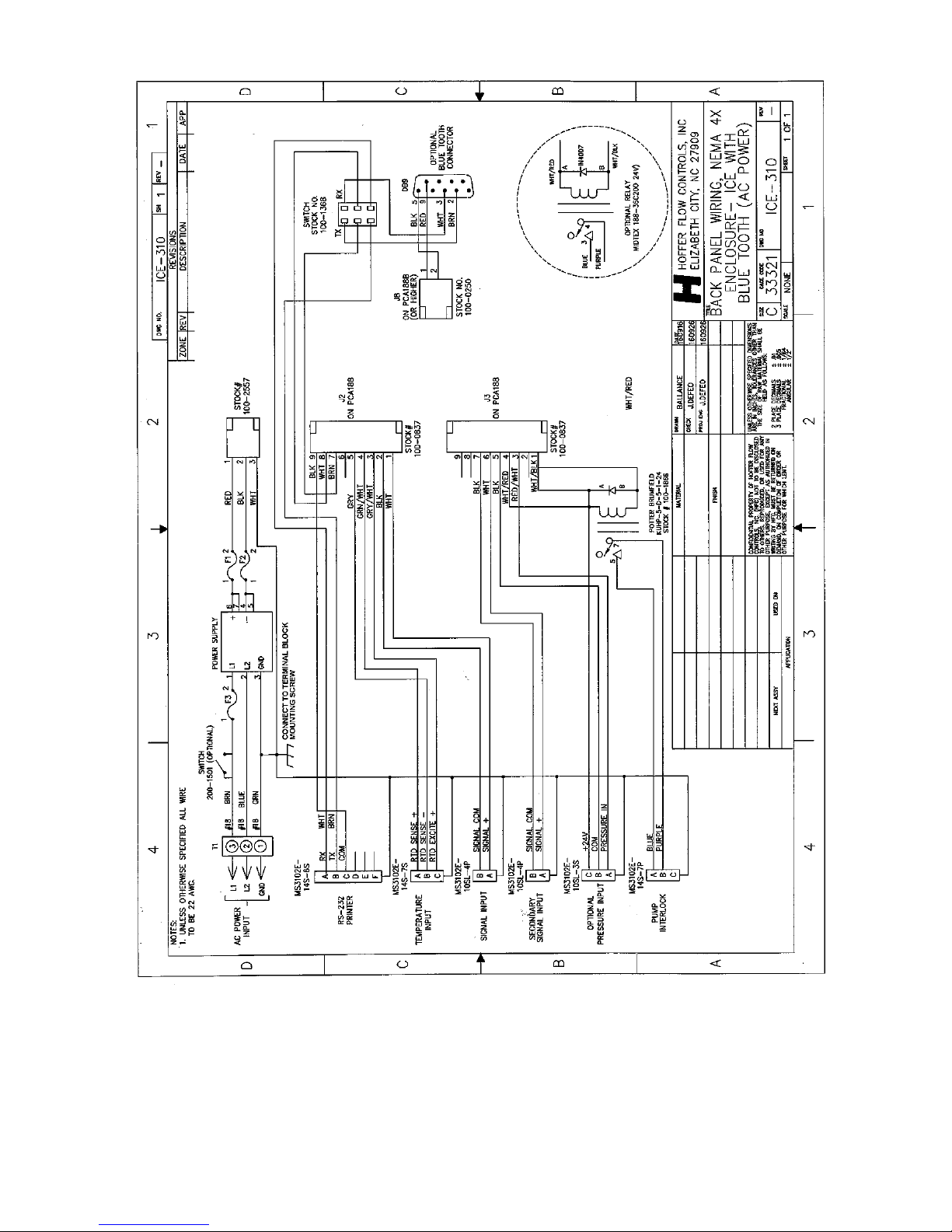
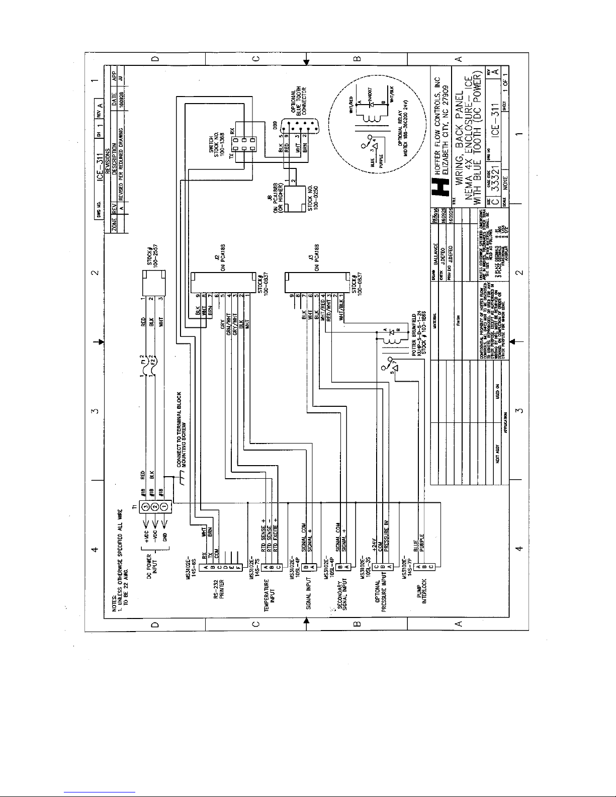
WIRING EXTERNAL CABLES TO EX-PROOF ICE.................... 27
APPENDIX B:
ICE WEIGHT SCALE CALIBRATION PROCEDURE .................. 35
Page 6

HP-319 i ICE Quick Start Guide
THIS PAGE INTENTIONALLY LEFT BLANK
Page 7

HP-319 1 ICE Quick Start Guide
INTRODUCTION
The ICE, Hoffer’s latest in Integrated Cryogenic Electronics, is engineered
using the latest technology to provide the most comprehensive features in a
truck-mounted delivery system. The typical application includes ICE as the
primary electronic indicating element of a bulk delivery system for CO2
and Cryogenic liquids. Other system components typically include a
turbine flow meter, temperature sensor, optional pressure sensor and
optional printer. ICE has been designed in accordance with the cryogenic
metering section of NIST HANDBOOK 44 and OIML R-81.
MODEL NUMBER DESIGNATION
MODEL ICE-( A )-( B )-( C )-( D )-( E )-( F )-( G )
SERVICE
PUMP INTERLOCK
PULSE SECURITY
POWER
HEATERS
MOUNTING
SPECIAL FEATURE
SERVICE
MODEL ICE-( A
)-( )-( )-( )-( )-( )-( )
OPTION
( A )
(1T) LIN/LOX/LAR - TEMP/COMP
(2T) CO2 - TEMP/COMP
(3T) NITROUS OXIDE - TEMP/COMP
(6T) LNG - TEMPERATURE COMP
(V) TRUE VOLUMETRIC
(P) FOR PRESSURE COMPENSATION (4-20 MA) ADD P TO
ANY ABOVE OPTIONS, SPECIFY PRESSURE RANGE.
INCLUDES PRESSURE TRANSMITTER CLEANED FOR OXYGEN
SERVICE AND 6' CABLE.
PUMP INTERLOCK OPTION
(240 VAC, IMAX 30 AMPS)
MODEL ICE-(
)-( B )-( )-( )-( )-( )-( )
OPTION
( B )
(PI) THE TEMPERATURE COMPENSATION OPTION MUST BE USED FOR
THE PUMP INTERLOCK OPTION
Page 8

HP-319 2 ICE Quick Start Guide
PULSE SECURITY OPTION
(240 VAC, IMAX 30 AMPS)
MODEL ICE-( )-( )-( C
)-( )-( )-( )-( )
OPTION
( C )
(PS) QUADRATURE INPUT PER ISO6551 LEVEL B COMPLIANT REQUIRES
SECOND MAG COIL ON TURBINE
(DOES NOT INCLUDE COILS NOR
TURBINE
)
(X) NONE
POWER
MODEL ICE-( )-( )-( )-( D
)-( )-( )-( )
OPTION
( D )
(12) 12 VDC STANDARD
(24) 24 VDC OPTION
(AC) 110/220 VAC POWER INPUT, STOCK #100-2052,
24 VDC POWER OUTPUT
(USED WITH PRINTER AND SKYDYNE CASE
AND (NS) MOUNTING OPTION)
HEATERS
MODEL ICE-( )-( )-( )-( )-( E
)-( )-( )
OPTION
( E )
(H) HEATER - STANDARD
MOUNTING
MODEL ICE-( )-( )-( )-( )-( )-( F
)-( )
OPTION
( F )
(S) STANDARD - FLAT MOUNT WITH SHOCKS
(SM) SHOCK MOUNTED SWIVEL STICK
(E) EX AND NEMA ENCLOSURES
(ND) NEMA 4X ENCLOSURE – FOR WALL MOUNTING
SPECIAL FEATURE
MODEL ICE-( )-( )-( )-( )-( )-( )-( G
)
OPTION
( G )
(SW) POWER SWITCH (WEATHER PROOF)
(CT) CUSTOM TICKETS
(BTA) AIR CABLE
(SP) ANY SPECIAL FEATURES THAT ARE NOT COVERED IN THE MODEL
NUMBER, USE A WRITTEN PESCRIPTION OF THE -SP.
(X) NO SPECIAL FEATURES
CABLES
(CABLES ARE SUPPLIED TO MATCH FEATURES PURCHASED)
NOTE: ALL CONNECTORS ARE ENVIRONMENTALLY WEATHERPROOF.
CABLE
PART NUMBER
10 FT. POWER CABLE SCA-10CU3-P
10 FT. SIGNAL CABLE SCA-10CC2-S
10 FT. TEMPERATURE CABLE SCA-10CC2-TA
10 FT. PUMP INTERLOCK SCA-10CU2-PI
NOTE: OTHER LENGTHS MAY BE ORDERED
Page 9

HP-319 3 ICE Quick Start Guide
Pump Cooling: 00:00
SYSTEM OVERVIEW
The front panel includes a 4.3″ full color graphical display and 3 rugged
panel sealed pushbuttons. The back panel includes environmentally
sealed military style electrical connectors for all standard and optional I/O
connections. The electronics are housed in a 4.35″ L X 6.54″ W X 4.125″
H aluminum enclosure with shock mounts or optional tilt bracket.
THE USER INTERFACE
ICE is designed to be a user-friendly component of the delivery system,
with an intuitive interface and easy access to the most common
operations. The pushbuttons allow the user to quickly CLEAR the
totalizer, PRINT a delivery ticket or change the MODE of operation.
ICE Front Panel
ICE is equipped with a touch screen feature that allows easy entry of data
parameters by authorized personnel. A numeric keypad simplifies the
entry of numeric data for password entry or programming.
The Numeric Keypad
The BACKSPACE button erases an incorrect entry.
Then ENTER button accepts the entered value.
Page 10

HP-319 4 ICE Quick Start Guide
MODES OF OPERATION
The ICE user interface is organized into 4 distinct modes of operation:
Delivery Mode
Maintenance Mode
Turbine Calibration Mode
System Configuration Mode
Although a password is required to make configuration changes, the
settings in each mode may be viewed by pressing the MODE button.
When prompted for a password, simply press MODE to advance to each
of the 3 other mode screens until returning to the Delivery Mode.
Delivery Mode
The Delivery Mode is the primary mode of operation for ICE, where all
delivery data and error messages are displayed on a single screen for easy
viewing. This is the default mode of operation when ICE is powered on,
or when the display timeout expires in one of the other modes.
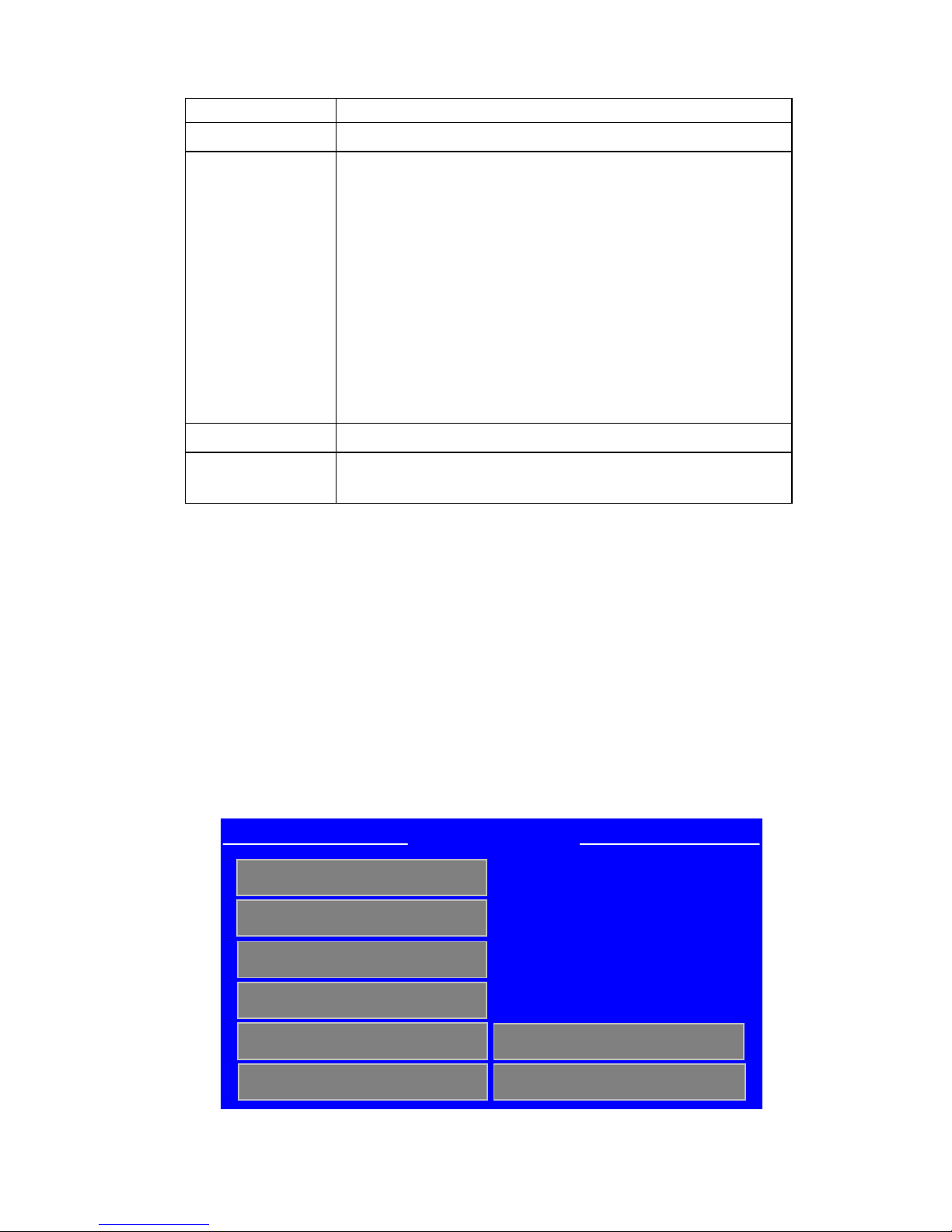
ICE Delivery Mode Screen
Page 11

HP-319 5 ICE Quick Start Guide
Display Item Digits Decimal Places Description
Delivery
Total
8 0 (00000000)
1 (0000000.0)
2 (000000.00)
The total quantity of
product dispensed in
selected volume or
mass units. Pressing
the CLEAR button
while in the Delivery
Mode will clear the
Delivery Total and log
the delivery
information to the trip
log.
Flow Rate 6 0 (000000)
The measured flow rate
expressed in units per
minute. Units are
determined by the
selection for Delivery
Total.
Temperature 4 1 (000.0)
The measured operating
temperature. If the
temperature sensor fails
or is removed, the
default temperature for
the selected liquid is
used for calculations
and indicated with the
word DEFAULT.
Pressure 4 bar – 2 (00.00)
psi – 1 (000.0)
The measured operating
pressure. If the
pressure sensor fails or
is removed, the default
pressure for the selected
liquid is used for
calculations and
indicated with the word
DEFAULT.
Accumulated
Total
12 0 (000000000000)
The total quantity of
product dispensed from
all deliveries. Units are
determined by the
selection for Delivery
Total.
Delivery Mode Display Parameters
Page 12
HP-319 6 ICE Quick Start Guide
Additional Delivery Mode Display Items
Display Item Description
Fluid Name The current fluid selected for dispensing.
Reference T&P
The reference temperature and pressure display is
dependent on the compensation method and delivery
units selected:
If compensation method is NONE, “Uncorrected”
will be displayed
If Compensation Method is something other than
NONE and Delivery Units are gallons or liters,
“NBP, (1 atm)” is displayed
If Compensation Method is something other than
NONE and Delivery Units are ft3, ft3X100 or
m3, the actual temperature and pressure reference
is displayed, i.e. 21 C, 101.325 kPa
Date/Time The current date and time.
Message Area
The bottom portion of the screen is reserved for
displaying error messages.
The CLEAR button clears the Delivery Total from the Delivery Mode
screen. The PRINT button prints a Delivery Ticket from the Delivery
Mode screen.
Maintenance Mode
The Maintenance Mode contains diagnostic fields, programmable fields
for Trailer Number and Date/Time as well as some additional Clear and
Print functions. Fields not enclosed in a gray button are read only items,
used for diagnostic purposes. If a correct password has been entered,
touching a gray button on the display will execute the Print or Clear
function or bring up the screen to edit a setting.
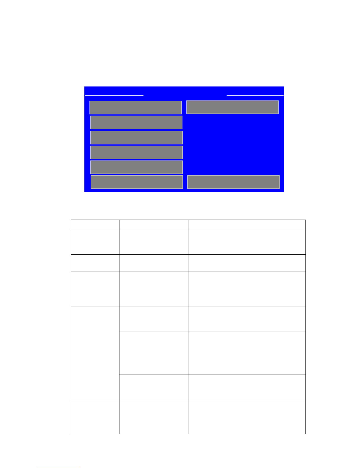
ICE Maintenance Mode Screen
Coil Ohms: 1081.8
Coil Hertz: 100.0
RTD Counts: 539
Internal Temp (F): 75.5
Print Confi
g
Clear Trip Report
Clear Acc Total
Audit Trail
Trailer: 12345678
12/22/2011::10:32
Maintenance Mode
Pump Hours: 153.2
Print Trip Report
Page 13

HP-319 7 ICE Quick Start Guide
Menu Item Selection Description
Print Config N/A
Prints the current ICE
configuration parameters to an
attached printer.
Print Trip Log 10, 20, 40, 100
Prints the most recent delivery
information from the trip log
for the selected number of
entries.
Clear Trip Log Clear Trip Log
Clears all delivery information
from the trip log and resets the
delivery number.
Clear Acc Total Clear Acc Total
Clears the Accumulated
Delivery Total.
Audit Trail 10, 20, 50, 100,
500, 1000
Displays/Prints the most
recent configuration changes
with date/time stamp for the
selected number of entries.
Trailer: Numeric Entry
Enter up to an 8-digit number
between 1 and 99999999.
Coil Ohms: Display Only
Displays the turbine coil
resistance in Ohms.
Coil Frequency: Display Only
Displays the turbine frequency
in Hertz.
RTD Counts: Display Only
Displays the A/D counts for
the RTD Temperature Input.
Internal Temp (F): Display Only
Displays the ambient
temperature inside the ICE
enclosure in degrees F.
Pump Hours: Display/Clear
Displays the number of hours
of liquid flow at a resolution
of 1/10
th
of an hour. Press the
Pump Hours button to reset.
Date/Time Numeric Entry
Enter the Date/Time as
mm/dd/yyyy::hh:mm
Maintenance Mode Menu Options
Page 14
HP-319 8 ICE Quick Start Guide
Turbine Calibration Mode
The Turbine Calibration Mode screen is used to configure all parameters
related to the turbine flowmeter calibration. Touching any gray button on
the display will bring up the edit screen for that field.
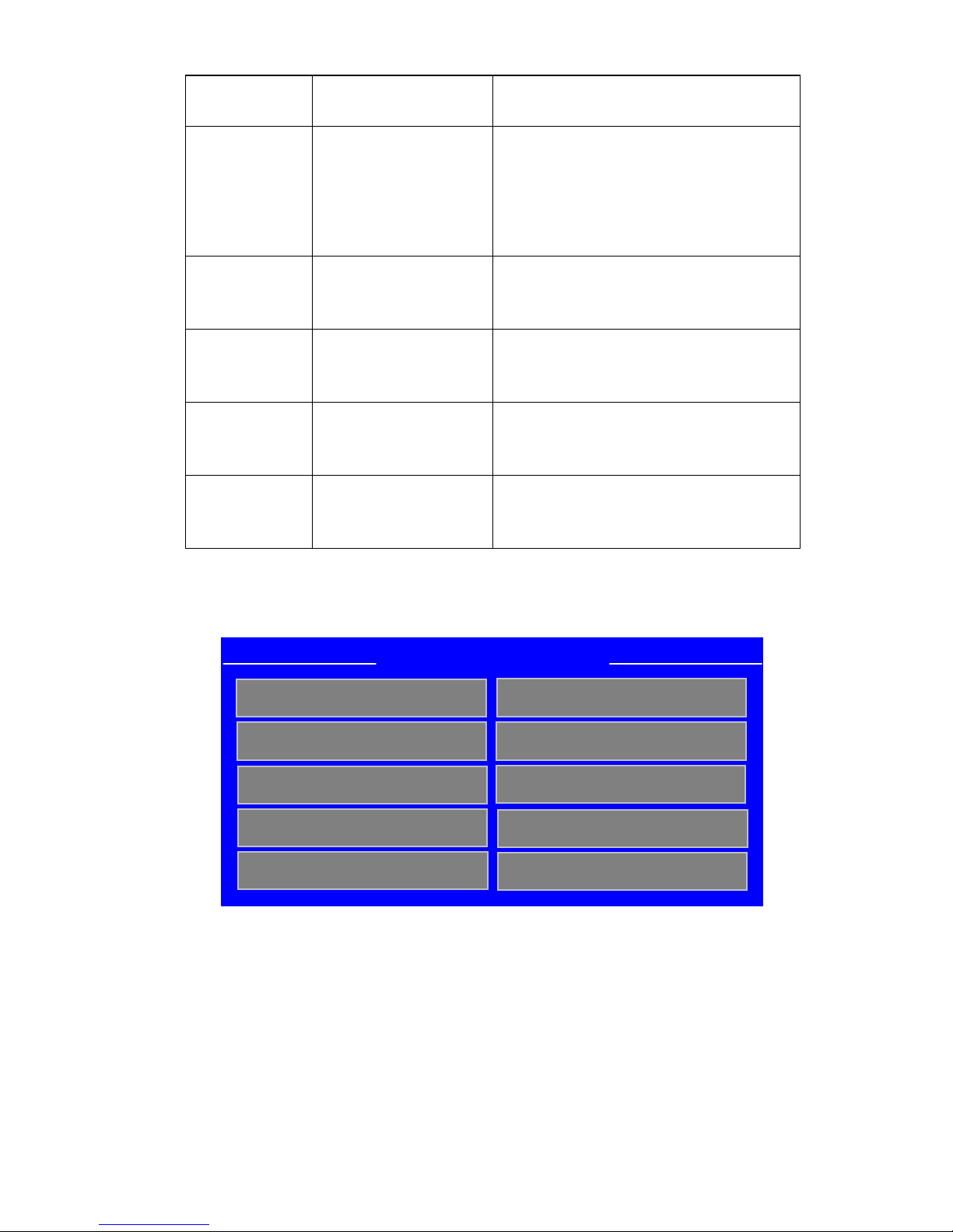
Turbine Calibration Mode Screen
Menu Item Selection Description
Meter SN
Numeric Entry Enter the turbine serial number.
Valid entry is a number up to a 9digits between 0 and 999999999.
Average K
Numeric Entry Enter a number between 0.001 and
99999.999 for the average k-factor.
K Method
Average
Linearization
Select flowmeter linearization
method as Average (single K) or
Linearization (5-point linearization
table)
Numeric Entry of
5 frequency and
k-factor points.
Enter the 5-point k-factor table.
Frequency 1-5 Frequency points 1-5 must be a
number between 0.100 and
5000.001 and must be at least
0.015 greater than the previous
frequency entry.
K-Factor
Table
K-factor 1-5 K-factor points 1-5 must be a
number between 0.001 and
99999.999.
Last Cal
Numeric Entry Enter the date of the last
calibration in the format
mm/dd/yyyy
Turbine Calibration Mode
Min Flow (gpm): 15.0
Max Flow (gpm): 225.0
Min Delivery (lb): 220.0
-
Page 15
HP-319 9 ICE Quick Start Guide
Next Cal Numeric Entry Enter the date the next calibration
is due in the format mm/dd/yyyy
Meter Size 0.75 inch
1.00 inch
1.25 inch
1.50 inch
2.00 inch
Select the appropriate turbine
meter size for the current
application.
Min Flow
(gpm):
Display Only Displays the minimum flowrate in
gallons per minute for the selected
meter size.
Max Flow
(gpm):
Display Only Displays the maximum flowrate in
gallons per minute for the selected
meter size.
Min
Delivery
(lb):
Display Only Displays the minimum delivery in
pounds for the selected meter size.
ICE SN Numeric Entry Enter the ICE serial number. Valid
entry is a number up to a 9-digits
between 0 and 999999999
Turbine Calibration Mode Menu Options
Frequency & K-Factor Table Screen
Frequency & K-Factor Table
Frequency 1 54.859
Frequency 2 54.876
Frequency 3 97.348
Frequency 4 138.628
Frequency 5 206.648
K
-Factor 1 222.927
K
-Factor 2 222.927
K
-Factor 3 224.481
K
-Factor 4 223.121
K
-Factor 5 220.800
Page 16
HP-319 10 ICE Quick Start Guide
System Configuration Mode
The System Configuration Mode provides configuration parameters
related to the flow measurement process and display preferences.
Touching any gray button on the display will bring up the edit screen for
that field.
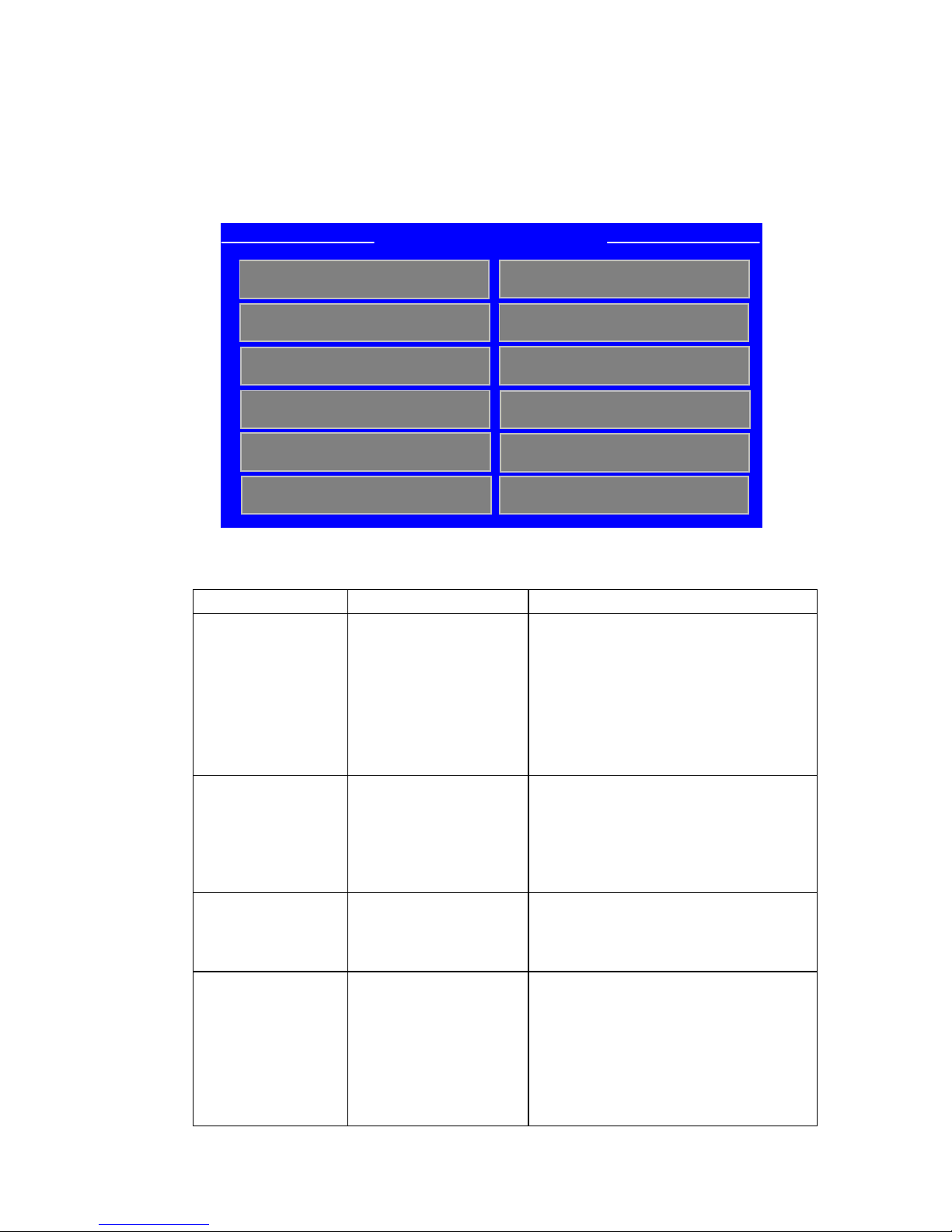
System Configuration Mode Screen
Menu Item Selection Description
Default Temp: Numeric Entry Enter the default value for the
fluid temperature to be used in
case of a temperature probe
failure. Valid entry is between
20 degrees Kelvin and the max
temperature in the compensation
range for a selected fluid.
Default Press: Numeric Entry Enter the default value for the
fluid temperature to be used in
case of a temperature probe
failure. Valid entry is between
0.0 and 1500.0 psia.
Total Decimal: 000
00.0
0.00
Select the display resolution for
the delivery total.
Fluid: LIN
LOX
LAR
CO2 SINGLE
CO2 DUAL
N2O
Select the fluid to be measured.
System Configuration Mode
Default Temp: 83.2
Default Press: 200.0
Total Decimal: 0.00
Fluid: LIN
Display T/O (sec) 600
Language: English
Temp Units:
K
Press Units: psia
Del Units: gallons
Compensation: T&P
Pump Delay (min) 1.0
Change Passwor
d
Page 17

HP-319 11 ICE Quick Start Guide
Menu Item Selection Description
Display T/O
(min)
Numeric Entry Enter the number of minutes
before ICE defaults back to the
Delivery Mode screen from
another mode. Valid entry is
between 1 and 99 minutes. The
display timeout is strictly time
based, not activity based.
Temp Units: Kelvin
Fahrenheit
Celsius
Select the units of measure for
Temperature.
Press Units: psia
psig
bar-a
bar-g
Select the units of measure for
Pressure.
Del Units: gallons
liters
ft3
ft3X100
m3
pounds
kilograms
Select the units of measure for
Delivery Total. Flowrate will be
displayed in the same units.
NOTE: If Compensation
Method is set to NONE, only
gallons and liters will be
available.
If Fluid Type is CO2, only
pounds and kilograms will be
available.
Compensation: None
Temperature
Temp & Default P
Temp & Pressure
Select the method of
compensation. Select None for
pure volumetric measurement.
Pump Delay
(min)
Numeric Entry Enter the number of minutes
between 0.0 and 99.0 used for
the cool down phase.
Change
Password
Numeric Entry Enter a 4-digit password
between 0000 and 9999. Default
password is 0000.
System Configuration Mode Menu Options
Page 18

HP-319 12 ICE Quick Start Guide
THE DELIVERY PROCESS
There are three basic steps to the delivery process for ICE:
Cooling the System
Dispensing the Product
Ending the Delivery
Cooling the System
When ICE is powered on, an RTD temperature sensor detects when liquid
is present at the pump and begins the Pump Cooling Timer. The timer,
which is displayed on the Delivery Mode Screen, counts down from the
value entered for the Pump Delay parameter in the System Configuration
Mode. If equipped, the Pump Relay is enabled after the timer reaches
zero and is disabled whenever gas is detected in the system.
Dispensing the Product
Once the system has been cooled down, the user should ensure that the
ICE is zeroed and ready for dispensing. When the delivery valve is
opened, the ICE begins totalizing the liquid flowing through the turbine
and the one-minute start phase begins. During the first minute of the
delivery, errors are displayed but not recorded in the Trip Log. After the
first minute of the delivery, any error occurring more than one minute is
recorded in the Trip Log. See section “Error Messages” for a
comprehensive list of error messages.
Ending the Delivery
After dispensing the required amount of liquid, the delivery valve is
closed to stop the liquid flow. The delivery remains active until one of
the following occurs:
A Delivery Ticket has been printed
The Delivery Total has been cleared
Once the PRINT or CLEAR function is executed, the active delivery
ends and the delivery information is recorded in the Trip Log.
While a delivery is active, the configuration may be viewed by
pressing MODE, however no changes to the configuration are
allowed. If an attempt is made to edit a configuration parameter
while a delivery is active, the following message is displayed:
“Delivery Active. Press CLEAR to exit.
Print ticket or clear total to end the delivery”
Pressing the CLEAR button removes the message and returns the
user to the previous view. Press the MODE button to return to the
Delivery Mode and press CLEAR or PRINT to end the active
delivery.
Page 19

HP-319 13 ICE Quick Start Guide
PRINT FUNCTIONS
Delivery Tickets, Trip Reports, Configuration parameters and the Audit
Trail may be printed by connecting an optional serial printer to the RS232
port.
The RS232 port settings are listed below and are not user configurable.
Handshaking: XON/OFF
Baud Rate: 9600
Word Length: 8 bits
Parity: None
When a print function is requested, ICE checks to ensure that the printer
is online and available and that there is paper in the printer. The
following messages may be displayed when executing print functions:
Message Description
Printer out of paper There is no paper detected in the printer
Printer offline, no response
from printer
The printer power is off or the serial cable
is not connected between the ICE and
printer.
Delivery Ticket
Press the PRINT button from the Delivery Mode screen to print a
Delivery Ticket. This action ends the current active delivery and logs the
delivery to the Trip Log. The number of decimal places for the Delivery
Total follows the selection for Total Decimal in the System Configuration
Mode.
Sample Delivery Ticket
METER DELIVERY TICKET
TRAILER NUMBER: 12345678
PRODUCT NAME: LIN
DELIVERY: 876543.21
UNITS: LITERS @ NBP
DATE: 01/13/2010
TIME: 13:55
DELIVERY NUMBER: 3
ACCUMULATED TOTAL: 109876543210
Page 20

HP-319 14 ICE Quick Start Guide
Configuration Printout
01/15/2010::10:40
Reference Conditions:
NIST (70 F, 14.7 psia)
Temperature units: Kelvin
Default temperature: 83.0
Pressure units: psia
Default pressure: 300.0
Delivery units: gallons
Total decimal places: 2
Fluid type: LOX
Display T/O (min): 10
Compensation:
TEMPERATURE & PRESSURE
Pump delay (min): 8
Trailer number: 12345678
Turbine serial number: 987654321
Meter size (inch): 2.00
K-factor method: Average
Average K-factor: 240.000
Last calibration date: 01/15/2010
Next calibration date: 01/15/2011
End of Configuration Printout
Trip Report
The Trip Report prints the stored trip log containing up to 100 previous
deliveries. It can be thought of as series of delivery tickets, with the
addition of any errors that were logged during each delivery.
From the Maintenance Mode screen, press the Print Trip Report button on
the display. A screen will be displayed to select the last 10, 20, 40 or 100
stored deliveries to be printed. A password is not required to print the
Trip Report.
If desired, after printing the Trip Report, press the Clear Trip Log button
to clear all delivery information from the trip log. The following delivery
will be logged as delivery number 1. A valid password entry is required
to clear the trip log.
Print Configuration
From the Maintenance Mode screen, press the Print Config button on the
display to print a detailed report containing the current configuration
settings. A password is not required to print the configuration settings.
Sample Configuration Printout
Page 21

HP-319 15 ICE Quick Start Guide
BEGIN AUDIT TRAIL
DATE: 02/18/2010
TIME: 16:20
1 12/18/2009::08:35 AKF
100.000 226.123
2 01/22/2010::13:22 FLU
LIN LOX
3 02/05/2010::11:05 MSZ
1.50 2.00
END OF AUDIT TRAIL
Audit Trail
The Audit Trail contains a log of the last 1000 configuration changes in
the following format:
1 Date/Time 3 Character Variable Code
Old Value New Value
From the Maintenance Mode screen, press the Audit Trail button on the
display to bring up a screen to select the number of most recent entries to
print. A password is not required to print the Audit Trail.
Sample Audit Trail Printout
Audit Trail
Variable Code
Description
DTE Date/Time
CAT Clear Accumulated Total
AKF Average K-Factor
KFM K-Factor Method
F01 – F05 Frequency 1 – 5 for Linearization Table
K01 – K05 K-Factor 1 – 5 for Linearization Table
MSZ Meter Size
DFT Default Temperature
DFP Default Pressure
FLU Fluid
TEU Temperature Units
PRU Pressure Units
DLU Delivery Units
CPM Compensation Method
Page 22

HP-319 16 ICE Quick Start Guide
ERROR MESSAGES
The ICE provides extensive self-checking capability to assist the user in
resolving faults and operational errors. Error messages are displayed on
the bottom portion of the Delivery Mode screen and are recorded in the
Trip Log if they occur for longer than one minute during a delivery.
DISPLAYED
MESSAGE
DESCRIPTION
GAS PRESENT,
TOTALIZATION
STOPPED
The operating temperature is warmer than the
specified liquid range and/or the operating
pressure is below the saturated pressure. There
is no longer liquid in the metering run. ICE
stops totalizing and disables the pump relay if
equipped.
GAS WARNING
The operating pressure is between saturated
pressure and 5 psia above saturated pressure.
The liquid is approaching a point where it may
contain bubbles, resulting in a delivery error.
HIGH FLOW RATE
The flow rate has exceeded the limit defined by
the Max Flow field for the selected meter size in
the Turbine Calibration Mode. This message
may appear if the turbine is being spun by gas.
LOW FLOW RATE
The flow rate has dropped below the limit
defined by the Min Flow field for the selected
meter size in the Turbine Calibration Mode.
COIL OPEN
Coil resistance is greater than 3000 Ohms. This
message will appear if the turbine signal cable is
removed.
COIL SHORT
Coil resistance is less than 200 Ohms.
TEMPERATURE
OPEN
Temperature probe resistance input is greater
than 1800 Ohms. This message will appear if
the temperature cable is removed.
TEMPERATURE
SHORT
Temperature probe resistance input is less than
90 Ohms.
PRESSURE FAIL
Pressure Analog input signal is less then 4 mA.
PRESSURE
OVERRANGE
Pressure Analog input signal has exceeded 20
mA.
LOW BATTERY
Internal battery has dropped below 2.2 Volts DC
and should be replaced as soon as possible.
MIN DELIVERY
NOT REACHED
This message is displayed on the Delivery
Ticket only and indicates that the minimum
measurable quantity for the selected meter size
has not been reached. The minimum delivery
amount for the selected meter size is indicated
on the Turbine Calibration Mode screen.
Page 23

HP-319 17 ICE Quick Start Guide
PULSE ERROR
Missing or double pulses have been detected in
a dual coil meter system.
EXCESS PULSE
ERROR
The number of missing or double pulses
detected has exceeded the acceptable percentage
of delivery total.
PULSE ERROR
EXCEEDS LIMIT
This message is displayed on the Delivery
Ticket only and indicates that the number of
missing or double pulses detected during a
delivery has exceeded the acceptable percentage
of delivery total.
Page 24

HP-319 18 ICE Quick Start Guide
INSTALLATION GUIDELINES
ICE should be installed with enough clearance to allow easy
access to all cables. Care should also be taken to install ICE
away from thawing pipes to minimize direct contact with
moisture.
Do not over tighten the mounting bolts. The recommended
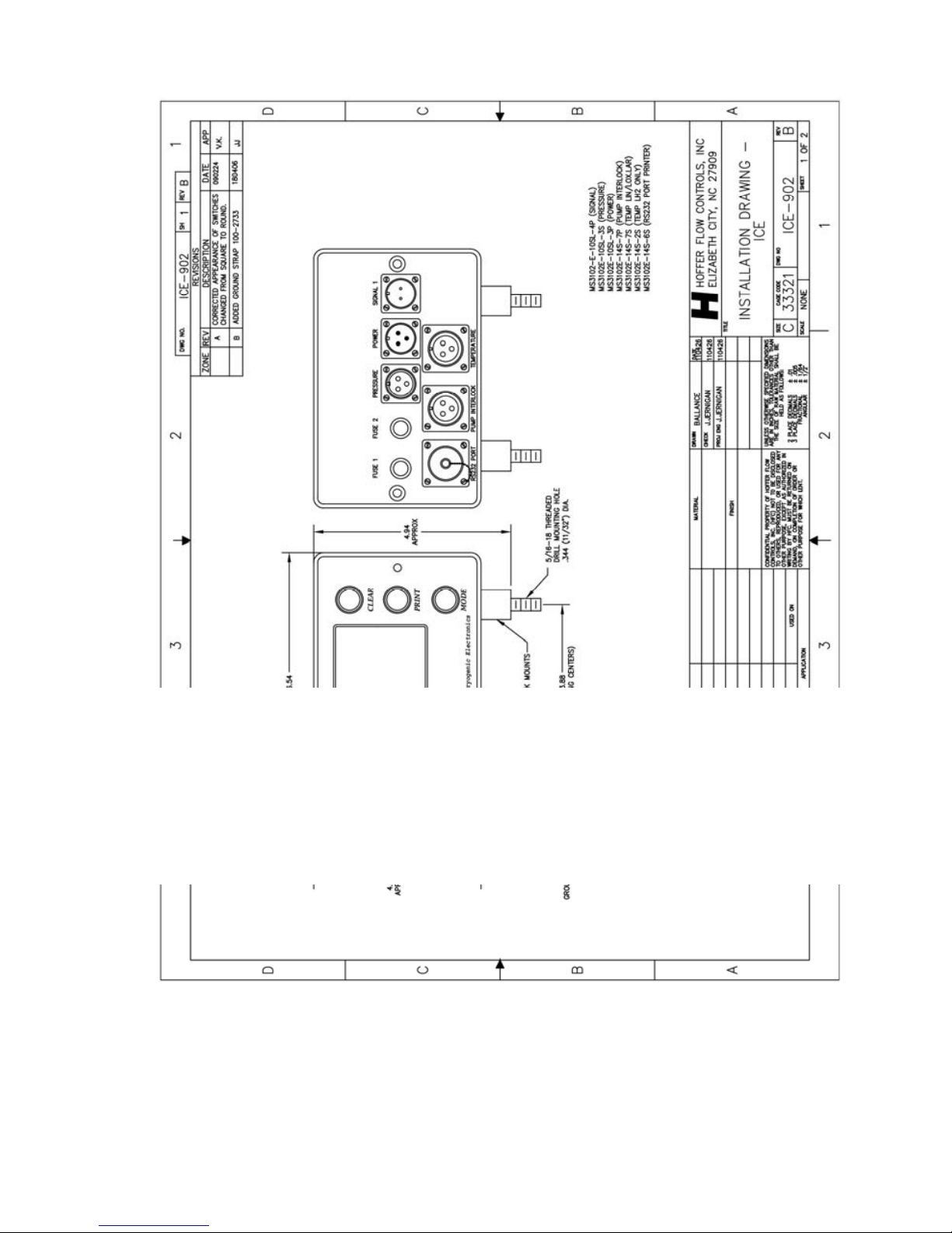
tightening torque for the shock mounts is 105 lbs-in.
Hoffer recommends powering ICE directly from the truck
battery. The DC+ power line may be wired through an external
switch if desired, or ICE may be ordered with an optional power
switch installed.
Hoffer recommends grounding the ICE enclosure to the trailer
chassis using the provided ground strap (part #100-2733) for
improved immunity to ESD (electrostatic discharge) and EMI
(electromagnetic interference).
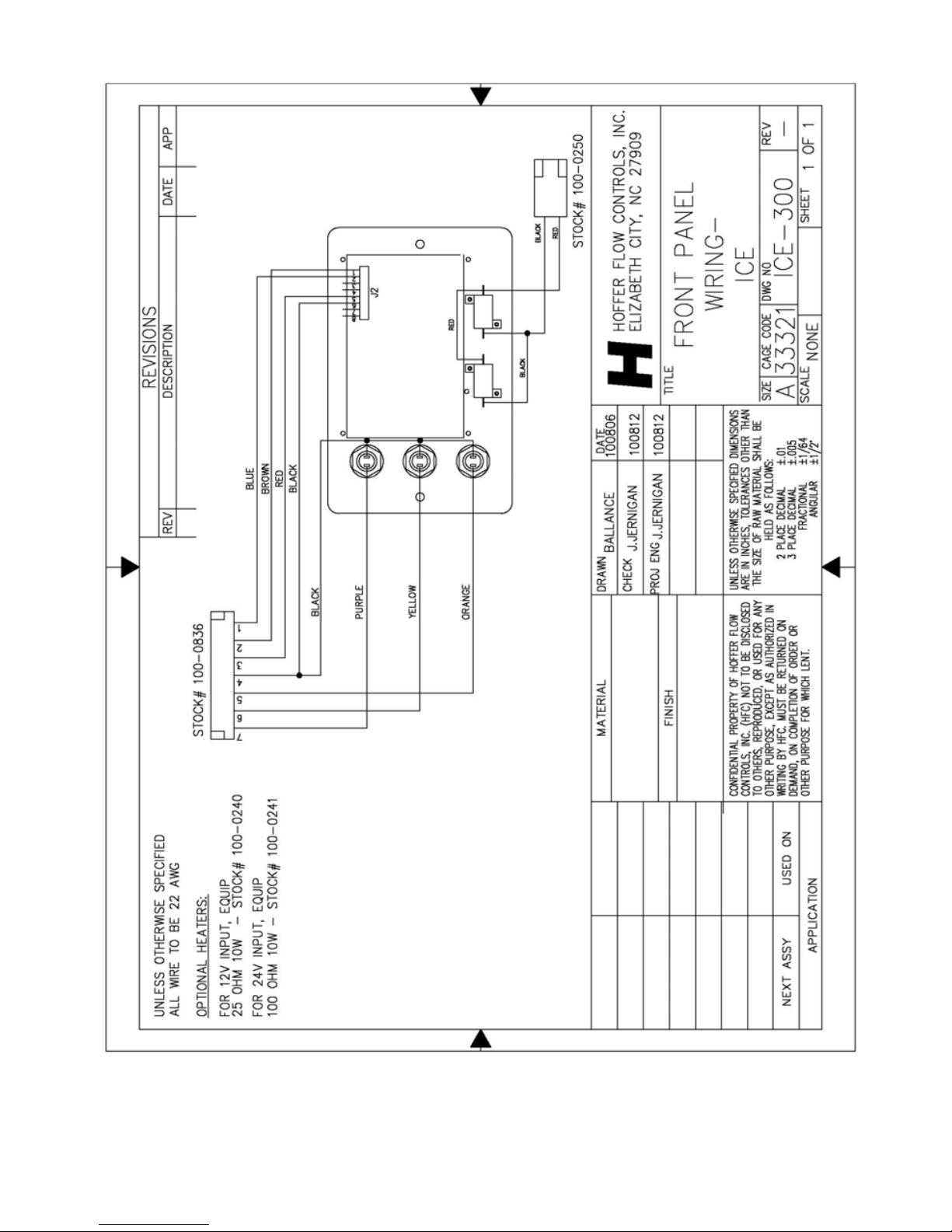
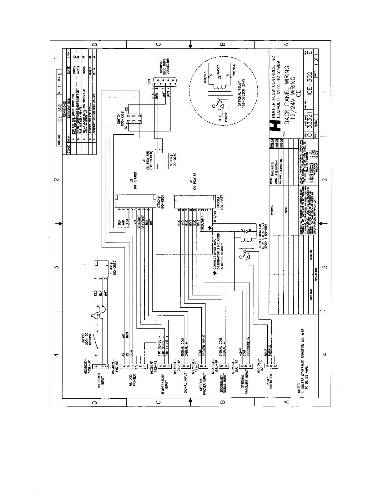
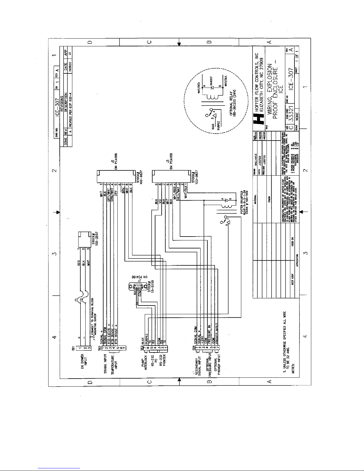
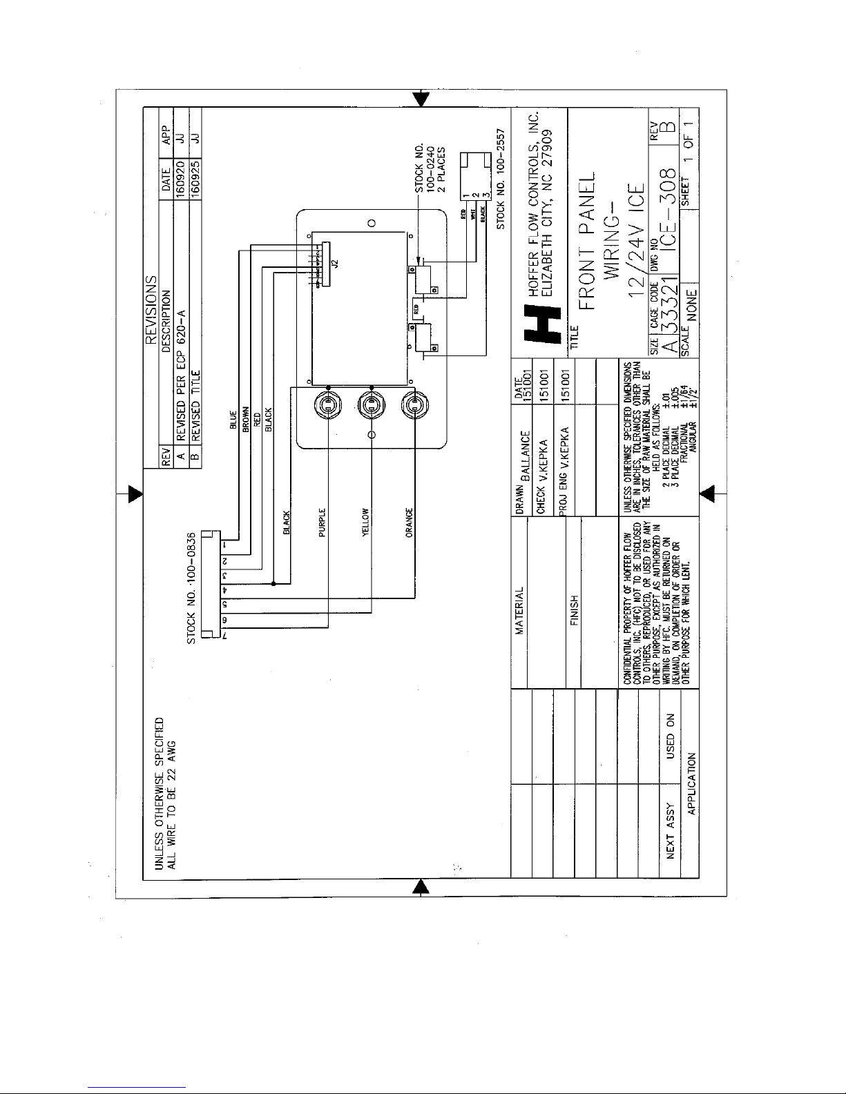
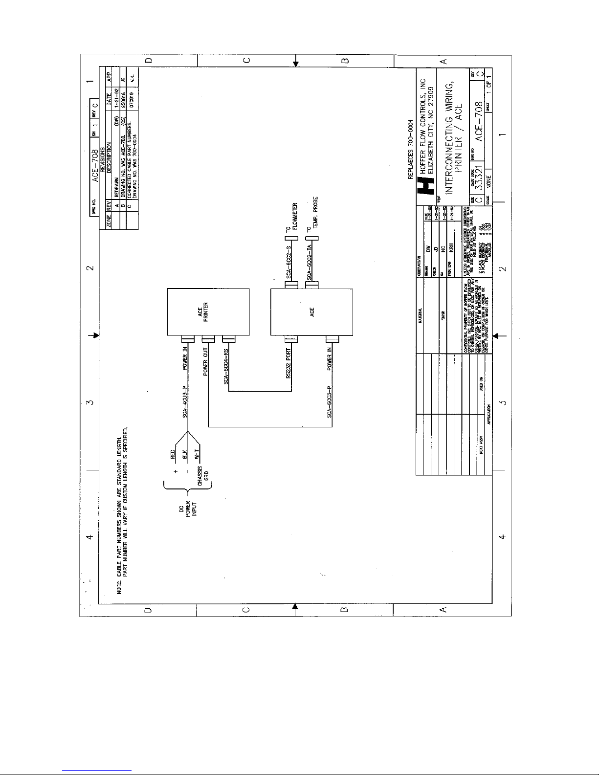
Refer to the installation drawings located in the back of this
manual for wiring information.
Page 25

HP-319 19 ICE Quick Start Guide
TECHNICAL SPECIFICATIONS
Environmental:
Operating Temperature: -20C to +70C
-40C to +70C with optional heater
Storage Temperature: -30C to +70C
Relative Humidity: 0-95% Non-condensing
Physical:
Enclosure Dimensions: 4.35” L x 6.54” W x 4.125” H
11.05cm x 16.61cm x 10.47cm
Fully assembled: 5.6” L x 6.54”W x 4.875”H
14.224cm x 16.61cm x 12.38cm
Weight: 4.2 lbs. (1.91 kg)
Approvals:
Design Approvals, Standards and Regulatory Compliance
CE
Emissions EN55022 & FCC Part 15
Immunity EN61000-4-2, EN61000-4-3, EN61000-4-4, EN61000-4-6
MIL-STD810G (Shock and Vibration)
NCWM Publication 14
NIST Handbook 44
National and State Legal for Trade
Australia – NMI
Brazil – INMETRO
China – OIML R81
European Union - MID
India – W & M
Indonesia & Malaysia - SIRIM
South Africa – SABS
United States – NTEP & CTEP
Enclosure:
Rugged aluminum NEMA 4X with shock
mounts
Optional swivel bracket
Optional Ex-Proof
Page 26

HP-319 20 ICE Quick Start Guide
Display:
4.3" color LCD with touch screen
Keypad:
Clear, Print and Mode Keys. Numeric
keypad for data entry via touch screen.
Power Supply:
Input Voltage: Range
10-30 Volts DC
NOTE: If Heaters or Pump Interlock option
is required, a nominal voltage of 12 VDC or
24 VDC must be specified
Current: 0.25A at 12VDC typical
1.25A with LCD heater option ON
Protection: Over current/reverse polarity protected
Fuses:
AGC 2 Amp
Battery:
User replaceable BR1225 3V lithium coin cell
for real time clock 2-4 years typical battery
life.
Flow Meter Input:
Frequency range: 0.2 to 5000 Hz
Amplitude: 15mV RMS to 50V RMS
Impedance: 10 k
Linearization:
Single K-Factor or 5-point flow meter
linearization
Pickup Coil
Diagnostics:
Coil Short/Open Detection
RTD Temperature Input:
RTD type: 1000 platinum probe, 2, 3 or 4-wire
Resolution: 12-bit
Accuracy: 0.025%
Diagnostics: Probe Short/Open Detection
Pressure Input:
Type: 4-20mA
Resolution: 12-bit
Accuracy: 0.025%
Diagnostics: Sensor Fail Detection
Pump Interlock Relay:
Form 1C (SPDT), 30A at 120/240 VAC
Serial
Communications:
RS-232 printer port
Baud Rate: 9600
Handshaking: XON/XOFF
Word Length: 8 bits
Parity: None
Page 27

HP-319 21 ICE Quick Start Guide
Miscellaneous System Features:
Non-volatile memory for configuration parameters and delivery
data
Real Time Clock
Security Features:
Audit Trail records last 1000 configuration
changes with Time/Date stamp
Password protection to prevent
unauthorized configuration changes
Diagnostic Features:
Failure detection for RTD, analog and flow
meter inputs
Multiple error messages
Tracking of pump operational hours
Measured Products:
Supports measurement of several predefined
liquids: LIN, LOX, LAR, CO2 Single Pipe,
CO2 Dual Pipe, LN2O and LNG
Units of Measure:
Rate and Total: gal, L, lb, kg, ft3, ft3 x 100, m3
Temperature: K, F, C
Pressure: psia, psig, bar-g, bar-a
Page 28

HP-319 22 ICE Quick Start Guide
THIS PAGE INTENTIONALLY LEFT BLANK
Page 29

HP-319 23 ICE Quick Start Guide
APPENDIX A
DRAWINGS
Page 30
HP-319 24 ICE Quick Start Guide
Page 31
HP-319 25 ICE Quick Start Guide
Page 32
HP-319 26 ICE Quick Start Guide
Page 33

HP-319 27 ICE Quick Start Guide
Wiring External Cables to Explosion Proof ICE
6/23/2015
CABLE PART
NUMBER
FUNCTION
CABLE
WIRE
COLOR
CONNECTION
TO ICE
TERMINAL
BLOCK
ICE
DESIGNATORS
DRAWING
ICE-307
RED TB1-1 +
BLK TB1-2 -
SCA-XLU3-P Power
WHT TB1-3 Chassis
WHT TB2-1 Signal +
SCA-XLT2-S Signal Input
BLK TB2-2 Signal -
WHT TB4-1 Signal +
SCA-XLT2-S
Secondary
Signal Input
BLK TB4-2 Signal -
WHT TB2-5 RTD Sense +
SCA-XLT2-TA
Temperature
Probe
BLK TB2-4 RTD Sense -
WHT TB3-2 RX
GRN TB3-1 TX
SCA-XCT4-RS
Serial Port
(Printer)
BLK TB3-3 COM
WHT TB3-4 RX
GRN TB3-5 TX
SCA-XCT4-RS Serial Port (PC)
BLK TB3-3 COM
RED TB3-6
SCA-XCU2-PI Pump Interlock
BLK TB3-7
RED TB4-3 +24V
SCA-10LT2-PT Pressure
BLK TB4-5 Pressure In
Page 34
HP-319 28 ICE Quick Start Guide
Page 35
HP-319 29 ICE Quick Start Guide
Page 36
HP-319 30 ICE Quick Start Guide
Page 37
HP-319 31 ICE Quick Start Guide
Page 38
HP-319 32 ICE Quick Start Guide
Page 39
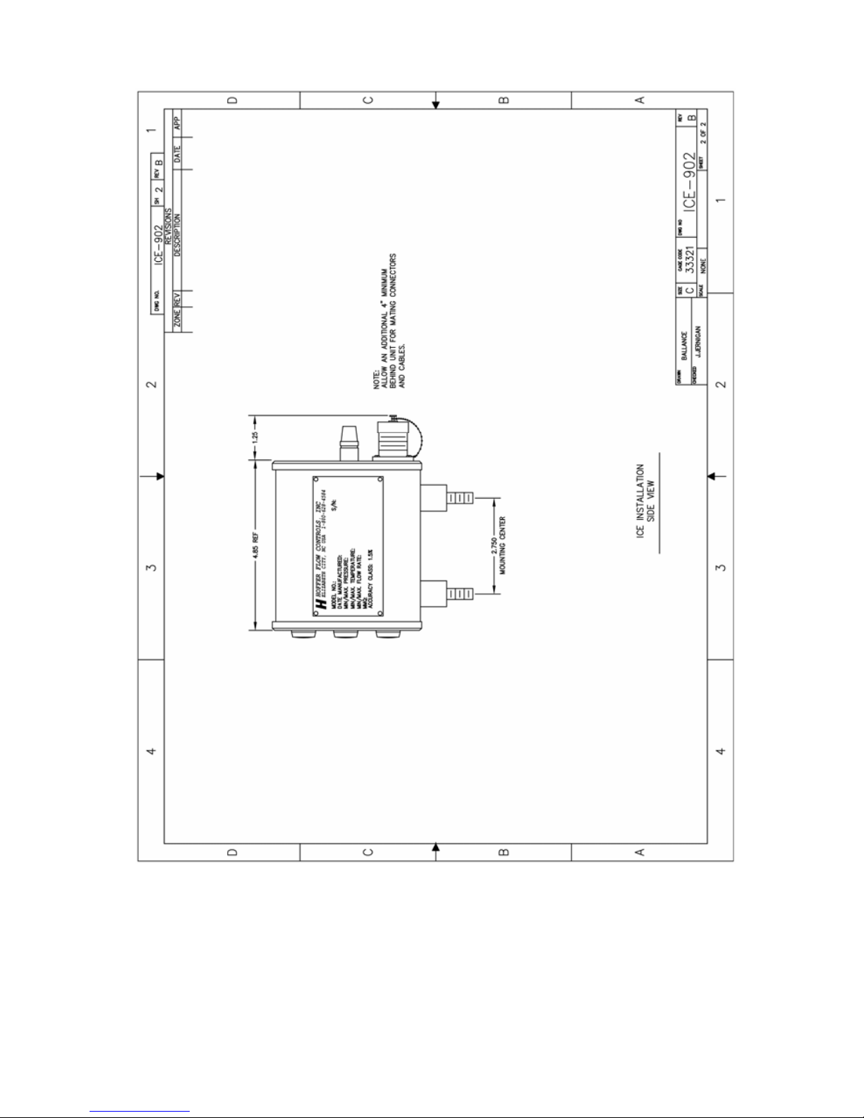
HP-319 33 ICE Quick Start Guide
Page 40

HP-319 34 ICE Quick Start Guide
THIS PAGE INTENTIONALLY LEFT BLANK
Page 41

HP-319 35 ICE Quick Start Guide
APPENDIX B
ICE WEIGHT SCALE
CALIBRATION PROCEDURE
Page 42

HP-319 36 ICE Quick Start Guide
ICE WEIGHT SCALE CALIBRATION PROCEDURE
Turbine flowmeters, when properly used, have been found to be
more accurate than most weight scales in determining the amount of
product delivered. Whenever possible use Hoffer portable Transfer
Standard SY-14B to perform ICE system calibrations. This
procedure requires the use of two tankers. One full of fresh cold
product and a empty tanker. Place the full tanker onto the scales.
Hook up the piping so that the full tanker will be pumping off to the
empty tanker. Follow the steps below:
1. Power up the ICE unit and enter the MENU.
2. Select CALIBRATION mode. Set K-METHOD to AVERAGE.
3. Record the AVERAGE K-FACTOR value.
4. Select SYSTEM CONFIGURATION MODE. Set DELIVERY
UNITS to mass (KG or LB).
5. Return the ICE to the OPERATING mode.
6. Pressurize and cool down the piping and flowmeter.
7. Press the CLEAR key on the ICE twice to clear the total.
8. Weigh the tanker and record its INITIAL WEIGHT. After
weighing the tanker start the pump.
9. To determine the TEST SAMPLE SIZE, divide the scale
increment by the accuracy requirement. For example, if scale
increment is 10 pounds and the accuracy requirement is 0.5%,
then 10 pounds / 0.005 = 2000 pounds. It is best to use an
accuracy requirement equal to the linearity rating of the
flowmeter (typically 0.5%)
10. Open the discharge valve and allow the tanker on the scales to
pump off an amount of fluid equal to the TEST SAMPLE SIZE.
After the TEST SAMPLE SIZE is pumped, close the discharge
valve. Weigh the tanker again, this is the tanker FINAL
WEIGHT. Calculate the SCALE TOTAL by subtracting the
FINAL WEIGHT from the INITIAL WEIGHT.
Page 43

HP-319 37 ICE Quick Start Guide
11. Record the DELIVERY TOTAL displayed on the ICE. Use the
following equation to calculate the new AVERAGE K-FACTOR:
AVERAGE_K_FACTOR
NEW
=
DELIVERY_TOTAL
________________
SCALE_TOTAL
x AVERAGE_K_FACTOR
OLD
12. Enter the ICE CALIBRATION mode and enter the new AVERAGE
K-FACTOR
13. Repeat Steps 6 through 9 to verify the new calibration is within the
accuracy requirements. If the new calibration is not within the
accuracy requirements then repeat Steps 6 through 12.
 Loading...