

Page 1

HP-313
July 2009
Model: HRT1
Flow Rate Indicator/Totalizer With
HART Communications Protocol
USER’S MANUAL
HP-313
April 2018
107 Kitty Hawk Lane ● P.O. Box 2145 ● Elizabeth City, NC 27909
1-800-628-4584 ● (252) 331-1997 ● Fax (252) 331-2886
www.hofferflow.com email: [email protected]
Page 2

Page 3

Page 4

Page 5

HFC 9907-B
_________________________________________________________
NOTICE
Hoffer Flow Controls, Inc. makes no warranty of any kind with regard to this
material, including, but not limited to, the implied warranties of merchantability
and fitness for a particular purpose.
This manual has been provided as an aid in installing, connecting, calibrating,
operating, and servicing this unit. Every precaution for accuracy has been taken in
the preparation of this manual; however, Hoffer Flow Controls, Inc. neither
assumes responsibility for any omissions or errors that may appear nor assumes
liability for any damages that result from the use of the products in accordance
with information contained in the manual.
HOFFER FLOW CONTROLS' policy is to provide a user manual for each item
supplied. Therefore, all applicable user manuals should be examined before
attempting to install or otherwise connect a number of related subsystems.
During installation, care must be taken to select the correct interconnecting wiring
drawing. The choice of an incorrect connection drawing may result in damage to the
system and/or one of the components.
Please review the complete model number of each item to be connected and locate
the appropriate manual(s) and/or drawing(s). Identify all model numbers exactly
before making any connections. A number of options and accessories may be added
to the main instrument, which are not shown on the basic user wiring. Consult the
appropriate option or accessory user manual before connecting it to the system. In
many cases, a system wiring drawing is available and may be requested from
Hoffer Flow Controls.
This document contains proprietary information, which is protected by
copyright. All rights are reserved. No part of this document may be photocopied,
reproduced, or translated to another language without the prior written consent
of Hoffer Flow Controls, Inc.
HOFFER FLOW CONTROLS’ policy is to make running changes, not model
changes, whenever an improvement is possible. This affords our customers the
latest in technology and engineering. The information contained in this
document is subject to change without notice.
THIS WARRANTY IS EXPRESSLY IN LIEU OF ALL OTHER WARRANTIES,
EXPRESSED OR IMPLIED, INCLUDING ANY IMPLIED WARRANTY OF
MERCHANTABILITY OR FITNESS FOR A PARTICULAR PURPOSE. HFC SHALL
NOT BE LIABLE FOR ANY LOSS OR DAMAGE RESULTING
, DIRECTLY OR INDIRECTLY,
FROM THE USE OR LOSS OF USE OF THE GOODS
. WITHOUT LIMITING THE
GENERALITY OF THE FOREGOING
, THIS EXCLUSION FROM LIABILITY EMBRACES THE
PURCHASER'S EXPENSES FOR DOWNTIME OR FOR MAKING UP DOWNTIME, DAMAGES
FOR WHICH THE
PURCHASER MAY BE LIABLE TO OTHER PERSONS, DAMAGES TO
PROPERTY
, AND INJURY TO OR DEATH OF ANY PERSONS. HFC NEITHER ASSUMES
NOR AUTHORIZES ANY PERSON TO ASSUME FOR IT ANY OTHER LIABILITY IN
CONNECTION WITH THE SALE OR USE OF
HFC'S GOODS, AND THERE ARE NO ORAL
AGREEMENTS OR WARRANTIES COLLATERAL TO OR AFFECTING THE AGREEMENT
.
PURCHASER'S SOLE AND EXCLUSIVE REMEDY IS THE REPAIR AND/OR REPLACEMENT OF
NONCONFORMING GOODS AS PROVIDED IN THE PRECEDING PARAGRAPHS
. HFC SHALL
NOT BE LIABLE FOR ANY OTHER DAMAGES WHATSOEVER INCLUDING INDIRECT
,
INCIDENTAL
, OR CONSEQUENTIAL DAMAGES.
Page 6

HFC 9907-B
________________________________________________________________
LIMITED WARRANTY POLICY FOR HOFFER FLOW CONTROLS
________________________________________________________________
HOFFER FLOW CONTROLS, INC. ("HFC") warrants HFC's Precision Series and API
Series of turbine flowmeters to be free from defects in material and workmanship under
normal use and service, only if such goods have been properly selected for the service
intended, properly installed and properly operated and maintained as described in the
turbine flowmeter manual. Reference "turbine flowmeter manual" for specific details. This
warranty shall extend for a period of five (5) years from the date of shipment to the
original purchaser and covers the Precision Series, API Series and CT Series of
flowmeters supplied with their standard hybrid ceramic ball bearings only. All other HFC
products carry a one (1) year warranty. This warranty is extended only to the original
purchaser ("Purchaser"). Purchaser's sole and exclusive remedy is the repair and/or
replacement of nonconforming goods as provided in the following paragraphs.
In the event Purchaser believes the Hoffer product is defective, the product must be
returned to HFC, transportation prepaid by Purchaser, within the appropriate warranty
period relative to the product. If HFC's inspection determines that the workmanship or
materials are defective and the required maintenance has been performed and, has been
properly installed and operated, the product will be either repaired or replaced, at HFC's
sole determination, free of additional charge, and the goods will be returned, transportation
paid by HFC, using a transportation method selected by HFC.
Prior to returning the product to HFC, Purchaser must obtain a Returned Material
Authorization (RMA) Number from HFC's Customer Service Department within 30 days
after discovery of a purported breach of warranty, but not later than the warranty period;
otherwise, such claims shall be deemed waived. See the Return Requests/inquiries Section
of this manual.
If HFC's inspection reveals the Hoffer product to be free of defects in material and
workmanship or such inspection reveals the goods were improperly used, improperly
installed, and/or improperly selected for service intended, HFC will notify the purchaser in
writing and will deliver the goods back to Purchaser upon receipt of Purchaser's written
instructions and agreement to pay the cost of transportation. If Purchaser does not respond
within thirty (30) days after notice from HFC, the goods will be disposed of in HFC's
discretion.
HFC does not warrant the product to meet the requirements of any safety code of any
state, municipality, or other jurisdiction, and Purchaser assumes all risk and liability
whatsoever resulting from the use thereof, whether used singlely or in combination with
other machines or apparatus.
This warranty shall not apply to any HFC product or parts thereof, which have been
repaired outside HFC's factory or altered in any way, or have been subject to misuse,
negligence, or accident, or have not been operated in accordance with HFC's printed
instructions or have been operated under conditions more severe than, or otherwise
exceeding, those set forth in the specifications.
________________________________________________________________
FOR NON-WARRANTY REPAIRS OR CALIBRATIONS, consult HOFFER FLOW CONTROLS
for current repair/calibration charges. Have the following information available
BEFORE
contacting HOFFER FLOW CONTROLS:
1.
P.O. number to cover the COST of the repair/calibration,
2. Model and serial number of the product, and
3. Repair instructions and/or specific problems relative to the product.
________________________________________________________________
Page 7

HRT1 HP-313
CONTENTS
1. INTRODUCTION------------------------------------------------1
Model Number Designation--------------------------------------------- 3
2. SPECIFICATIONS AND PRODUCT FEATURES-------7
2.1 General ---------------------------------------------------------- 7
2.2 Inputs ------------------------------------------------------------ 8
2.3 DC Power/Loop Powered------------------------------------ 8
2.4 Analog Output ------------------------------------------------- 9
2.5 Pulse Output---------------------------------------------------- 9
2.6 Alarm 1 and Alarm 2----------------------------------------- 9
2.7 Physical---------------------------------------------------------- 9
Product Features-------------------------------------------------------- 9
3. INSTALLATION----------------------------------------------- 11
3.1 4-20 mA Current Loop--------------------------------------13
3.2 Flowmeter Input----------------------------------------------15
3.3 Pulse Output---------------------------------------------------16
3.4 Alarm Outputs------------------------------------------------16
3.5 Wiring Summary---------------------------------------------18
4. CONFIGURATION-------------------------------------------- 19
4.1 Local Configuration -----------------------------------------19
4.2 Default Configuration---------------------------------------22
5. OPERATION AND MAINTENANCE--------------------- 23
5.1 Display Parameters ------------------------------------------23
5.2 Saving Grand Total------------------------------------------23
5.3 Clearing the Total--------------------------------------------23
5.4 System Response Time --------------------------------------24
5.5 Error Conditions ---------------------------------------------24
5.6 Battery Replacement Indication --------------------------25
6. HART COMMUNICATIONS------------------------------- 27
6.1 Dynamic Variables-------------------------------------------27
6.2 Universal Commands----------------------------------------28
6.3 Common-Practice Commands-----------------------------28
6.4 Device-Specific Commands--------------------------------29
6.5 Device Status --------------------------------------------------31
6.6 Additional Device Status------------------------------------32
6.7 EDDL – Process Variables ---------------------------------35
6.8 EDDL – Device Diagnostics --------------------------------36
6.9 EDDL – Online -----------------------------------------------36
7. MAINTENANCE----------------------------------------------- 41
Page 8

HP-313 HRT1
APPENDIX A – DEFAULT CONFIGURATION------------ 43
APPENDIX B – Declaration and Conformity----------------- 45
APPENDIX C – Installation Drawings and Conditions
for Safe Use for Certified Systems------------------------------- 47
Page 9

Introduction 1
HRT1 HP-313
1. INTRODUCTION
The HRT1 is a loop-powered microprocessor-based flow rate indicator
and totalizer with HART Field Communications Protocol. The
instrument can accept a low-level signal from a magnetic type pickup
coil, logic level pulse signal, or contact closure on the signal input.
Pulses from the signal input are counted and converted into volume and
rate values based on flowmeter calibration settings in the instrument.
The total volume and flow rate is displayed on a two-line liquid crystal
display (LCD). The top line is an 8-digit Total Volume display and the
bottom is a 5-digit Rate display. A 4-20 mA analog signal proportional
to the flowrate is output on the current loop. The HRT1 is configurable
by way of the instrument keypad or via HART communications.
Figure 1 – HRT1 Front Panel Overview
Optional features include 20-point linearization to correct for
flowmeter non-linearities, a Scaled Pulse Output and 2 Alarm Outputs
configurable for Rate or Total.
The instrument may be housed in a NEMA 4X polycarbonate
enclosure, which may be wall mounted or directly mounted on a
flowmeter using an optional riser. Other options include panel mount
or an EX proof enclosure for hazardous areas.
Page 10

Introduction 2
HP-313 HRT1
This instrument is designed to conform to the EMC-Directive of the
Council of European Communities 89/336/EEC and the following
standards:
Generic Emission Standard EN 61000-6-3
Residential, Commercial & Light Industry Environment.
Generic Immunity Standard EN 61000-6-1
Residential, Commercial & Light Industry Environment.
Electrostatic discharge requirements EN 61000-4-2
Radiated, radio-frequency, electromagnetic immunity EN 61000-4-3
Electrical fast transient/burst requirements EN 61000-4-4
Immunity to conducted disturbances EN 61000-4-6
Page 11

Introduction 3
HRT1 HP-313
MODEL NUMBER DESIGNATION
MODEL HRT1
FLOW RATE INDICATOR/TOTALIZER
WITH HART® COMMUNICATIONS PROTOCOL
MODEL HRT1-( A )-( B )-( C )-( D )-( E )-( F )-( G )
ENCLOSURE STYLE
PULSE INPUT
A
NALOG OUTPUT
PULSE OUTPUT
A
LARMS
MOUNTING
SPECIAL FEATURES
ENCLOSURE STYLE
MODEL HRT1-( A )-( )-( )-( )-( )-( )-( )
OPTION ( A )
(2) NEMA 4X ENCLOSURE
(HRT1 MOUNTED BEHIND CLEAR COVER)
(3*) ALUMINUM CASTING POWDER COATED ENCLOSURE (IP66)
(P) PANEL MOUNT ENCLOSURE (IP40)
(PD) PANEL MOUNT ENCLOSURE WITH CLEAR DOOR AND LOCK (IP40)
(4) NEMA 1 ENCLOSURE
(HRT1 MOUNTED TO THE OUTSIDE OF CLEAR COVER FOR DOOR/DRY
INSTALLATION ONLY)
(5) NEMA 4X ENCLOSURE/HRT1 ENCLOSURE
(MOUNTED BEHIND CLEAR COVER WITH SUNSHADE)
(7*) STAINLESS STEEL ENCLOSURE (IP66)
(ALL CONDUIT PORTS ARE 3/4" FNPT)
*OPTIONS FOR ENCLOSURE STYLE 3 AND 7:
(_M) M20 CONDUIT THREAD (NOT ALLOWED FOR USE IN CANADA)
(_S) SUNSHADE
PULSE INPUT
MODEL HRT1-( )-( B )-( )-( )-( )-( )-( )
OPTION
( B )
(M) MAGNETIC COIL, DRY PULSE CONTACT
(R) ISOLATED PULSE, RPM, RPR, HALL EFFECT COILS
Page 12

Introduction 4
HP-313 HRT1
ANALOG OUTPUT
MODEL HRT1-( )-( )-( C )-( )-( )-( )-( )
OPTION
( C )
(W) WIRED 4-20MA LOOP POWERED
PULSE OUTPUT
MODEL HRT1-(
)-( )-( )-( D )-( )-( )-( )
OPTION
( D )
(5) 0-5 TTL/CMOS
(OC) OPEN COLLECTOR
(V) 8-30 VDC WITH PULLUP TO VDC+
ALARMS
TWO OPTO-ISOLATED ALARMS WITH USER-DEFINED LEVELS FOR RATE
AND/OR TOTAL
MODEL HRT1-( )-( )-( )-( )-( E )-( )-( )
OPTION
( E )
(5) 0-5 TTL/CMOS
(OC) OPEN COLLECTOR
(V) 8-30 VDC WITH PULLUP TO VDC+
MOUNTING
MODEL HRT1-(
)-( )-( )-( )-( )-( F )-( )
OPTION
( F )
(F) NEMA 4X STYLE 2 ENCLOSURE MOUNTED ON TURBINE.
MUST BE USED WITH “X” RISER TURBINE OPTION.
(FHT) 8" LONG TEMPERATURE RISER FOR NEMA 4X STYLE 2
ENCLOSURES MOUNTED ON TURBINE. REQUIRED WHEN
FLUID TEMPERATURES EXCEED 140 DEG. F. USED WITH “X”
RISER TURBINE OPTION.
(FX) STYLE 3 OR STYLE 7 ENCLOSURES MOUNTED ON TURBINE.
MUST BE USED WITH “X” RISER TURBINE OPTION.
(FXHT) 8" LONG TEMPERATURE RISER FOR STYLE 3 OR STYLE 7
ENCLOSURES MOUNTED ON TURBINE. REQUIRED WHEN
TEMPERATURES EXCEEDS 140 DEG. F.
USED WITH “X” RISER TURBINE OPTION.
(NP) ENCLOSURE PIPE MOUNTING KIT; 2" PIPE OR SMALLER.
SPECIFY IF PIPE IS VERTICAL OR HORIZONTAL.
Page 13

Introduction 5
HRT1 HP-313
SYSTEM CERTIFIED MOUNTING OPTIONS FOR ENCLOSURE STYLE 3 AND 7:
(MX_) METER MOUNTED
NOTE: USED WITH “X” RISER, AND 1" X ¾" SS ADAPTER. PROCESS
TEMP -40°C TO +70°C.
(MA_) METER MOUNTED
NOTE: USE WITH A (X-ATEX) RISER. PROCESS TEMP -40°C
TO +70°C.
(RX_) REMOTE MOUNTED
NOTE: USE WITH “X” RISER. INCLUDES “E2” JUNCTION BOX AND
1" X 3/4" SS ADAPTER.
(RA_) REMOTE MOUNTED
NOTE: USE WITH A (X-ATEX) RISER. INCLUDES “E2” JUNCTION BOX.
UNION OPTIONS:
(___U1) OPTIONAL 1" MALE X 1" FEMALE EX-PROOF UNION
NOTE: USE WITH MX AND RX OPTIONS
(___U2) OPTIONAL 3/4" MALE X 3/4" FEMALE EX-PROOF UNION
NOTE: USE WITH MA AND RA OPTIONS
EXPLOSION-PROOF ENCLOSURE RATINGS:
Canada/US Zones
Ex db IIB+H
2
T6; Gb; Ex tb IIIC T72°C Db; IP66;
Class I, Zone 1, AEx db IIB+H2 T6; Gb; Zone 21, AEx tb IIIC T72°C Db; IP66:
ATEX/IECEX :
II 2 G Ex db IIB+H2 T6 Gb
II 2 D Ex tb IIIC T72°C Db IP66
T1-T6 = -40°C to +70°C
SPECIAL FEATURES
MODEL HRT1-( )-( )-( )-( )-( )-( )-( G )
OPTION
( G )
(CE) CE MARK REQUIRED FOR EUROPE
(SP) ANY SPECIAL FEATURES THAT ARE NOT COVERED IN THE
MODEL NUMBER, USE A WRITTEN DESCRIPTION OF THE -SP.
(X) NO SPECIAL FEATURES.
Page 14

Introduction 6
HP-313 HRT1
This Page Intentionally Left Blank
Page 15

Specifications and Product Features 7
HRT1 HP-313
2. SPECIFICATIONS AND PRODUCT FEATURES
General Specifications
2.1 General
Display: LCD, updated every 2.0 seconds.
Total: 8 digits 0.26" high. Resettable using a
magnet, a contact closure to power common
on the RESET input terminal, from the front
panel keypad or via HART communications.
Total Units:
GAL, LIT, FT3, M3, BBL, & “blank”.
Grand Total: 8 digits 0.26" high, non-resettable. Value
stored once per minute in non-volatile
memory. Grand Total is displayed for 15
seconds after pressing the
▲ button.
Rate: 5 digits 0.5" high.
Rate Units: /SEC, /MIN, /HR, & /DAY
K-factor: The pulses per unit of Total (e.g.
pulses/gallon) are configurable in the range
0.001 to 99,999,999.
Linearization: Up to 20 points.
Decimal Points: Decimal Point positions are configurable for
0, .0, .00, or .000 for both rate and total.
Accuracy: Total: 1 count, Rate: 0.01%
Page 16

Specifications and Product Features 8
HP-313 HRT1
2.2 Inputs
Magnetic Pickup:
Frequency Range: 0.2 Hz to 5000 Hz.
Signal Level: 30 mV
P-P
to 30 V
P-P
.
Opto-Isolated DC Pulse:
Frequency Range: 0 Hz to 3000 Hz.
Signal Type: DC pulse.
High (Logic 1): 4 to 30 VDC
Low (Logic 0): < 1 VDC
Min Pulse width: 0.1 msec
Contact Closure:
Frequency Range: 0 Hz to 5000 Hz
Signal Type: Contact closure, Sig+ Terminal to DC
common
Internal Pull-up: 220 kΩ to +3.3 VDC
Reset:
Signal Type: Contact closure, Reset Terminal to DC
common
Min On: 25 msec
Internal Pull-up: 100 kΩ to +3.3 VDC
External Magnet: Activates internal reed switch
2.3 DC Power/Loop Powered
Voltage: 8 to 30 VDC
Current: < 24 mA
Loop Burden: 8 VDC maximum
Supply Backup: C size Lithium or battery pack for Ex
system
Battery Life: 8 months typical
Protection: Reverse polarity protected
Page 17

Specifications and Product Features 9
HRT1 HP-313
2.4 Analog Output
Scale: 4 – 20 mA follows rate.
Accuracy: 0.02% of Full Scale @ 20ºC.
Temperature drift: 40 ppm/°C
Update Time: 2.0 seconds.
Connection: Two wire.
Protection: Reverse polarity protected
2.5 Pulse Output
Type: 0-5V TTL, 0-Supply Voltage, Open collector
(30 VDC, 100 mA)
Divider: 1, 10, 100, or OFF
Rate & Duration: See below.
Frequency (Hz): 1 2 4 8
On/Off (msec) 500 250 125 62.5
2.6 Alarm 1 and Alarm 2
Type: 0-5V TTL, 0-Supply Voltage, Open collector
(30 VDC, 100 mA)
Function: Rate or Total
2.7 Physical
Temperature: Operating: -40°F (-40C) to 158°F (70C).
Humidity: 0 – 90% Non-condensing.
Packaging: NEMA 4X, Panel mount or Explosion proof
Dimensions for
NEMA 4X enclosure:
4.33" (110 mm) wide x 4.33" (110 mm)
long 4.33" (110 mm) tall.
Page 18

Specifications and Product Features 10
HRT1 HP-313
Product Features
HART Field Communications Protocol, Revision 7.0
LCD display
8-Digit Total display with configurable decimal point
location
5-Digit Rate display with configurable decimal point
location
8-Digit, Non-resettable Grand Total display
4-button membrane keypad
Pulse Input supports turbine as well as many other pulse
generating flowmeters
Up to 20-Point Linearization to correct for flowmeter
non-linearities
4-20 mA analog output proportional to flow rate
Optional Scaled Pulse Output representing an increment
of volume for each pulse
2 Optional Alarm Outputs configurable for Rate or Total
Magnetically operated switch for Total reset
Internal battery backup
Configuration and Grand Total stored in non-volatile
memory. Grand Total saved once per minute.
Page 19

Installation 11
HRT1 HP-313
3. INSTALLATION
Field Wiring Connections
Connections are made to the HRT1 on two six-position terminal
blocks, labeled as terminals 1-12 (Fig. 3.1). Connections are made to
the terminal blocks using wire gauges 16-28 AWG, tightening Torque
0.22 to 0.25Nm. A ten-position DIP switch (SW2) located on the back
of PCA186A provides a quick selection of various input/output
options. The following pages illustrate connections and switch settings
for various options.
To make field wiring connections to the HRT1-4 option (NEMA 4X,
front panel mounted on the outside of the clear cover), complete the
following:
1. Loosen the four cover screws.
2. Remove the clear cover and HRT1 assembly.
3. Use a small flat blade screwdriver and turn counter-clockwise
to loosen the proper terminal screw.
4. Insert wire and turn terminal screw clockwise to tighten.
5. Lightly pull on wire to ensure proper connection.
For the HRT1-2 option (NEMA 4X, front panel mounted behind the
clear cover):
1. Loosen the four cover screws and remove the clear cover.
2. Remove the four #4-40 x 5/16” black oxide screws from the
corners of the panel and remove the HRT1 assembly.
3. Use a small flat blade screwdriver and turn counter-clockwise
to loosen the proper terminal screw.
4. Insert wire and turn terminal screw clockwise to tighten.
5. Lightly pull on wire to ensure proper connection.
For the HRT1-3 or HRT1-3A option (Explosion proof enclosure):
1. Unscrew the cover of the enclosure counter-clockwise until it
separates from the body of the enclosure.
2. Remove the two #4-40 x 1” black oxide screws from the top
left and bottom right section of the front panel.
3. Remove the HRT1 assembly from the mounting standoffs.
4. Use a small flat blade screwdriver and turn counter-clockwise
to loosen the proper terminal screw.
5. Insert wire and turn terminal screw clockwise to tighten.
6. Lightly pull on wire to ensure proper connection.
Warning: When contained in an Explosion-Proof
enclosure, do not open the cover while circuits are live in
hazardous atmospheres.
Page 20

Installation 12
HP-313 HRT1
NOTE:
When installing HRT1 unit directly on the turbine meter, follow the
steps below to avoid twisting signal wires from pickup coil.
1. Remove the HRT1 electronics from the enclosure.
2. Disconnect the signal wires from the HRT1 electronics, if
connected.
3. Mount/Thread the enclosure on the turbine flowmeter.
4. Reconnect the signal cable to the HRT1 unit.
Page 21

Installation 13
HRT1 HP-313
3.1 4-20 mA Current Loop
The HRT1 is powered from a two-wire 4-20 mA current loop, in the
voltage range of 8-30 Volts DC, depending on the loop resistance. One
C-Size 3.6V Lithium or battery pack for Ex d system, is included as a
backup power supply to ensure that volume accumulation will not be
interrupted during a power failure. Switch 2 of SW-2 must be ON for
loop power.
Figure 3.1.1 – 4-20mA Loop Wiring and Switch Settings
Figure 3.1.2 – Loop Load Limitations
Operating
Region
1
6
3
JP2
1
8
TB2
TB1
4
SW2
9
7
10
11
12
5
2
-+
POWER SUPPLY
8-30 VDC
Supply Voltage VS Load
0
200
400
600
800
1000
1200
0 5 10 15 20 25 30
Supply Voltage
Load (Ohms)
Page 22
Installation 14
HP-313 HRT1
1
The HRT1 outputs a 4-20mA analog signal on the current loop that is
proportional to the calculated flow rate. The 4mA and 20mA settings
referred to as outLo and outHi respectively, may be configured from
the front panel of the instrument or via HART communications.
3.2 Flowmeter Input
The flowmeter input accepts a low-level sinusoidal signal from a
magnetic type pickup coil, contact closure, or an isolated DC pulse
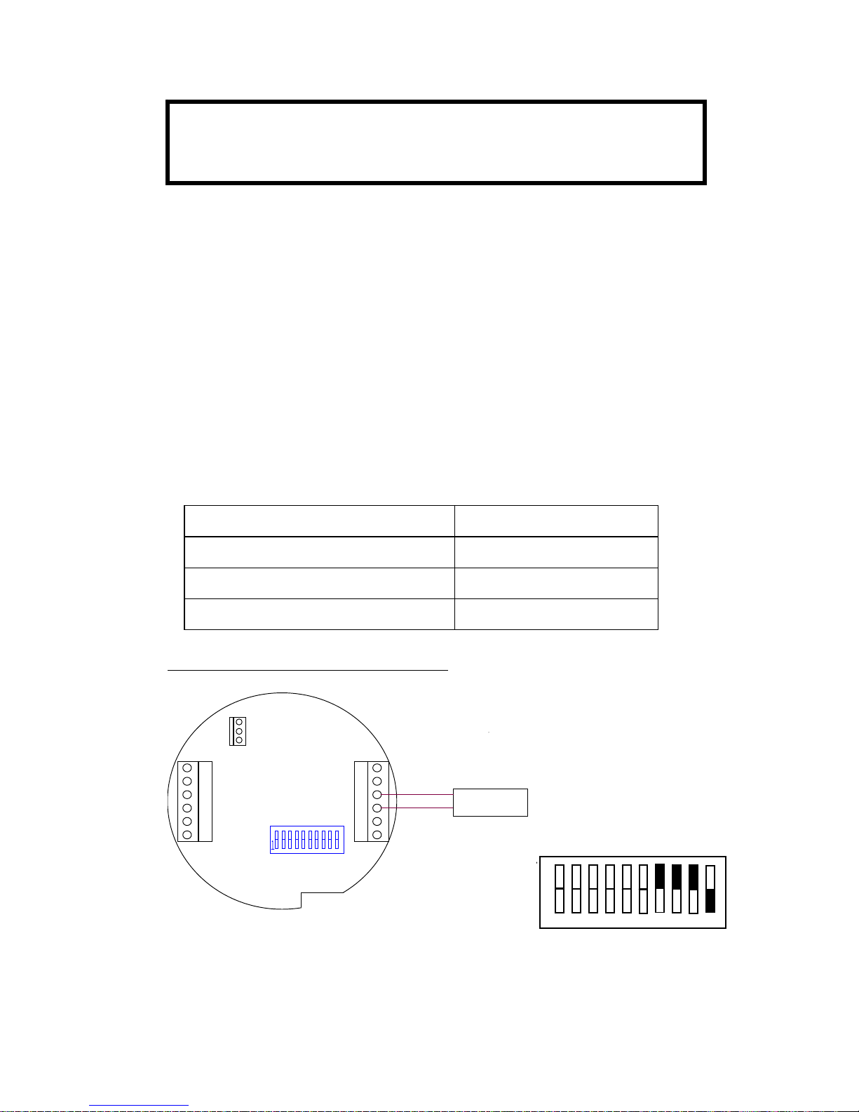
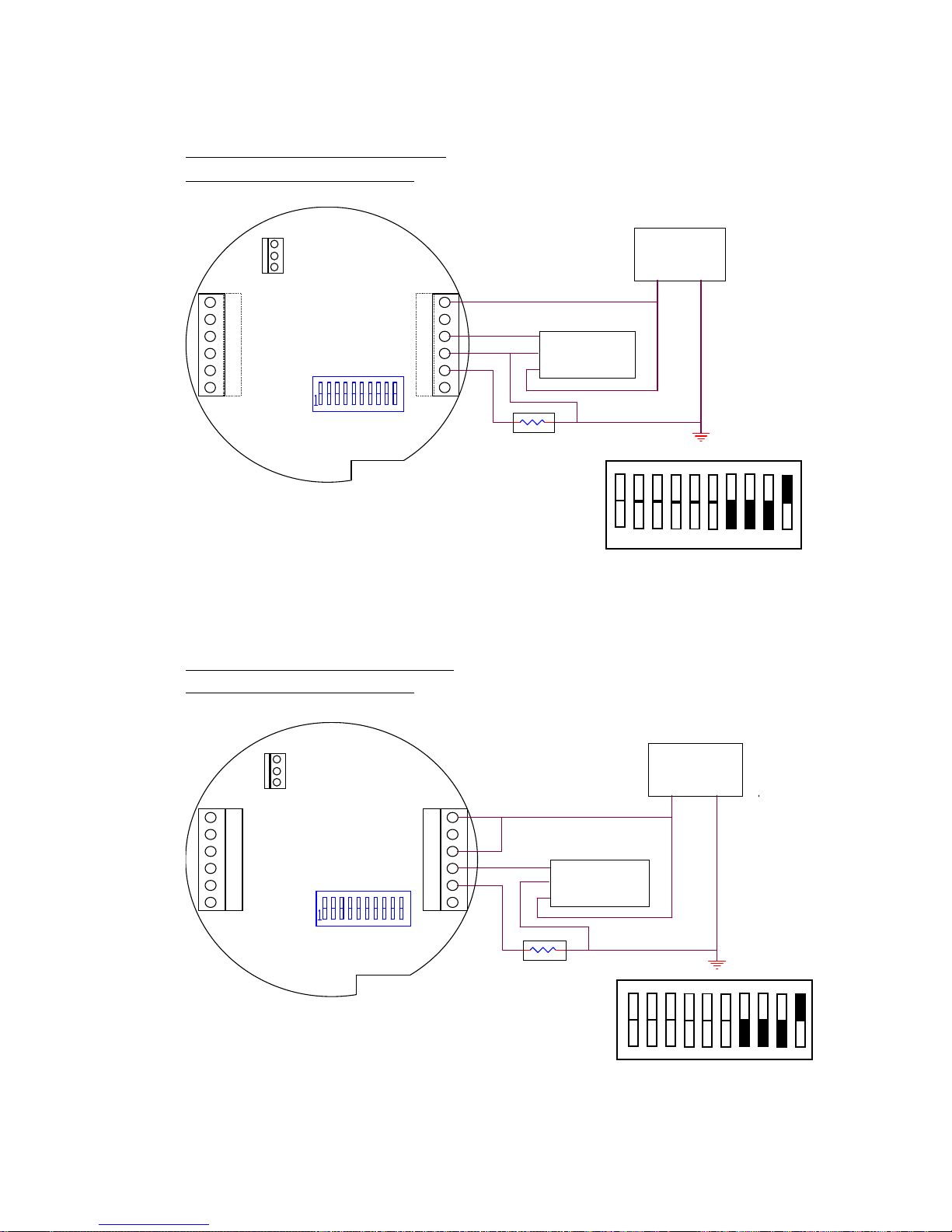
signal. Switches 7, 8, 9 and 10 on SW-2 must be set according to the
type of flowmeter input to be used. Proper switch settings will be made
at the factory if the flowmeter input is specified at the time of order.
SW-2 SWITCH SETTINGS FOR FLOWMETER INPUT OPTIONS:
INPUT OPTION SW-2 SETTINGS
Mag pickup / Contact Closure 7, 8 AND 9 ON (10 OFF)
Isolated Redi-Pulse - TTL 10 ON (7, 8 AND 9 OFF)
Isolated Redi-Pulse – Open-Collector 10 ON (7, 8 AND 9 OFF)
Magnetic Pickup Coil/Contact Closure
JP2
B
7
2
TB2
10
SIG IN -
11
1
4
SW2
SIG IN +
9
TB1
12
3
8
6
A
Magnetic Pickup
5
Figure 3.2.1 – Magnetic Pickup/Contact Closure Wiring and Switch Settings
SW2
1 2 3 4 5 6 7 8 9 10
NOTE:
HART Communications requires a loop resistance between 250
and 1100 Ohms.
Page 23
Installation 15
HRT1 HP-313
SW2
SW2
Isolated Redi-Pulse (TTL Pulse)
Requires 3-Wire Installation
P
OWER SUPPLY
8
-
3
0 VDC
63S
IG IN
-
JP2
1
8
TB2
TB14
9
S
W2
10
11
7
12
52S
IG IN +
B
A
Redi-Pulse Pickup
C
+
-
Figure 3.2.2 – Isolated Redi-Pulse TTL Wiring and Switch Settings
Isolated Redi-Pulse (Open Collector)
Requires 3-Wire Installation
POWER SUPPLY
8-30 VDC
JP2
6
3
1
8
TB2
TB1
4
SW2
9
7
10
11
12
5
2
Redi-Pulse Pickup
B
A
C
+
-
Figure 3.2.3 – Isolated Redi-Pulse Open-Collector Wiring and Switch Settings
1 2 3 4 5 6 7 8 9 10
1
1
1 2 3 4 5 6 7 8 9 10
Page 24
Installation 16
HP-313 HRT1
3.3 Pulse Output
HRT1 Pulse Output can be configured for turbine raw frequency or for
unit of measure scaled for the least significant digit of the displayed
total. A scaling factor of 1, 10 or 100 is available to reduce or increase
the resolution of the pulse output. For example, if the Total Decimal
Point is set to 0000000.0, and the Pulse Scale is 1, then 1 pulse will be
output for each tenth (0.1) of a unit of measure. Changing the Pulse
Scale to 10, would result in an output pulse for each 1.0 unit of
measure. The output must be scaled so that the pulse frequency does
not exceed the Pulse Frequency setting (8 Hz. Max) at the maximum
flow rate.
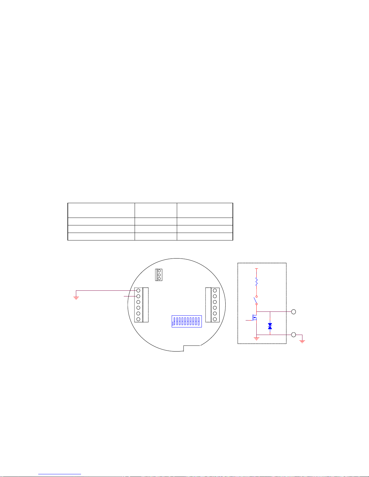
The Pulse Output may be configured as an Open Collector, 0-5V (TTL)
or Internal pullup to VDC+ using dip switch SW-2.
SW-2 SETTINGS AND PROTECTION DIODE VALUE FOR PULSE
OUTPUT OPTIONS:
OPTION SW-2
SETTINGS
TS1
OPEN COLLECTOR 6 OFF 36V TRANSORB
TTL 6 ON 5.1V ZENER
PULLUP TO VDC+ 6 ON 36V TRANSORB
63JP218T
B2
PULSE OUTPUT +
TB1
49SW2117
10122
5
SW2-
610K
DC_IN(+)
1
1 PULSE OUTPUT +
1
2
Figure 3.3.1 – Pulse Output Wiring and Circuit Overview
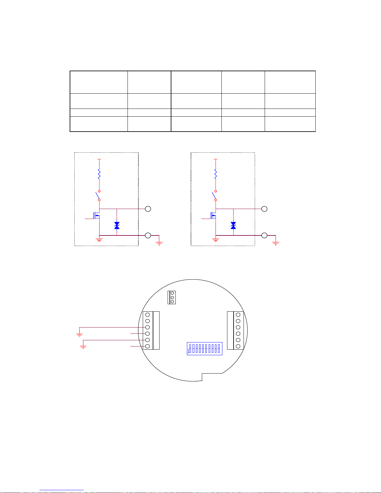
3.4 Alarm Outputs
HRT1 provides an optional Alarm Output feature, which includes 2
alarm outputs configurable for Rate or Total. The outputs may be
configured as an Open Collector, 0-5V (TTL) or Internal pullup to
VDC+.
Page 25
Installation 17
HRT1 HP-313
SW-2 SETTINGS AND PROTECTION DIODE VALUES FOR ALARM
OUTPUT OPTIONS:
OPTION ALARM1
SW-2
SETTINGS
ALARM1
TS5
ALARM2
SW-2
SETTINGS
ALARM2
TS2
OPEN
COLLECTOR
4 OFF 36V
TRANSORB
5 OFF 36V
TRANSORB
TTL 4ON 5.1V ZENER 5 ON 5.1V ZENER
PULLUP TO
VDC+
4 ON 36V
TRANSORB
5 ON 36V
TRANSORB
Figure 3.4.1 – Alarm Outputs Circuit Overview
JP2
6
3
1
ALARM2 OUTPUT +
8
TB2
ALARM1 OUTPUT +
TB1
4
9
SW2
10
11
7
12
5
2
Figure 3.4.2 – Alarm Outputs Wiring
SW2-4
10K
DC_IN(+)
A
LARM 1
7
9
10A
LARM 2
8
SW2-5
10K
DC_IN(+)
Page 26

Installation 18
HP-313 HRT1
3.5 Wiring Summary
When installing HRT1, it is a good practice to use shielded cables for
all input and output signals. The shield should be connected to the
chassis ground lug on the HRT1. The shield on the opposite end of the
cable should be left open.
This wiring practice is mandatory in order to comply with the
requirements for Electromagnetic Compatibility, as per EMC-Directive
89/336/EEC of the Council of European Community.
Page 27
Configuration 19
HRT1 HP-313
4. CONFIGURATION
The HRT1 is fully configurable, with all parameters being stored in
non-volatile memory. The instrument may be configured locally using
the front panel keys or remotely via a HART communicator.
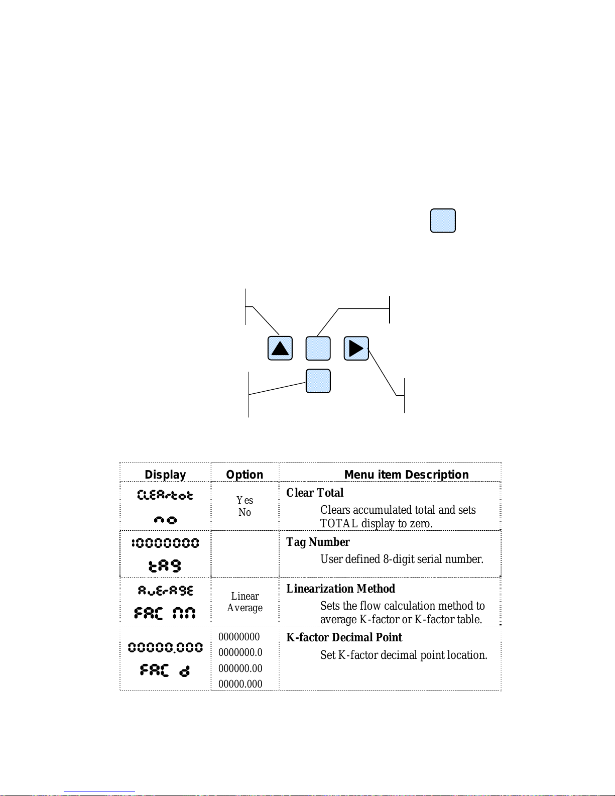
4.1 Local Configuration
Each consecutive press moves to the next menu item. The functions for
each button in the configuration mode are described below.
The following table outlines all menu items in the configuration mode:
Display Option Menu item Description
CLEArtot
no
Yes
No
Clear Total
Clears accumulated total and sets
TOTAL display to zero.
10000000
tA9
Tag Number
User defined 8-digit serial number.
AuErAgE
FAC NN
Linear
Average
Linearization Method
Sets the flow calculation method to
average K-factor or K-factor table.
00000.000
FAC d
00000000
0000000.0
000000.00
00000.000
K-factor Decimal Point
Set K-factor decimal point location.
The local configuration mode is entered by pressing the
P
b
utton.
Press for next menu item.
Press to edit selection and
to accept selection.
Press to move cursor
one position to the right.
Press to increment digit or
change selection.
P
OK
Page 28
Configuration 20
HP-313 HRT1
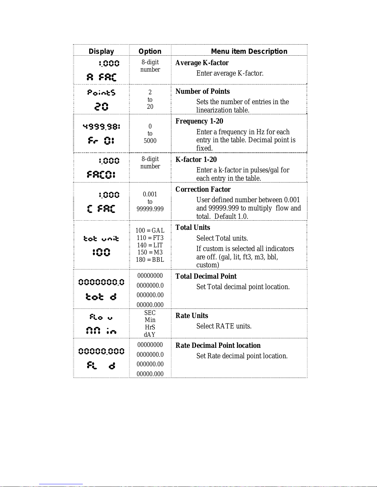
Display Option Menu item Description
1.000
A FAC
8-digit
number
Average K-factor
Enter average K-factor.
PointS
20
2
to
20
Number of Points
Sets the number of entries in the
linearization table.
4999.981
Fr 01
0
to
5000
Frequency 1-20
Enter a frequency in Hz for each
entry in the table. Decimal point is
fixed.
1.000
FAC01
8-digit
number
K-factor 1-20
Enter a k-factor in pulses/gal for
each entry in the table.
1.000
C FAC
0.001
to
99999.999
Correction Factor
User defined number between 0.001
and 99999.999 to multiply flow and
total. Default 1.0.
tot unit
100
100 = GAL
110 = FT3
140 = LIT
150 = M3
180 = BBL
Total Units
Select Total units.
If custom is selected all indicators
are off. (gal, lit, ft3, m3, bbl,
custom)
0000000.0
tot d
00000000
0000000.0
000000.00
00000.000
Total Decimal Point
Set Total decimal point location.
FLo u
NN in
SEC
Min
HrS
dAY
Rate Units
Select RATE units.
00000.000
FL d
00000000
0000000.0
000000.00
00000.000
Rate Decimal Point location
Set Rate decimal point location.
Page 29
Configuration 21
HRT1 HP-313
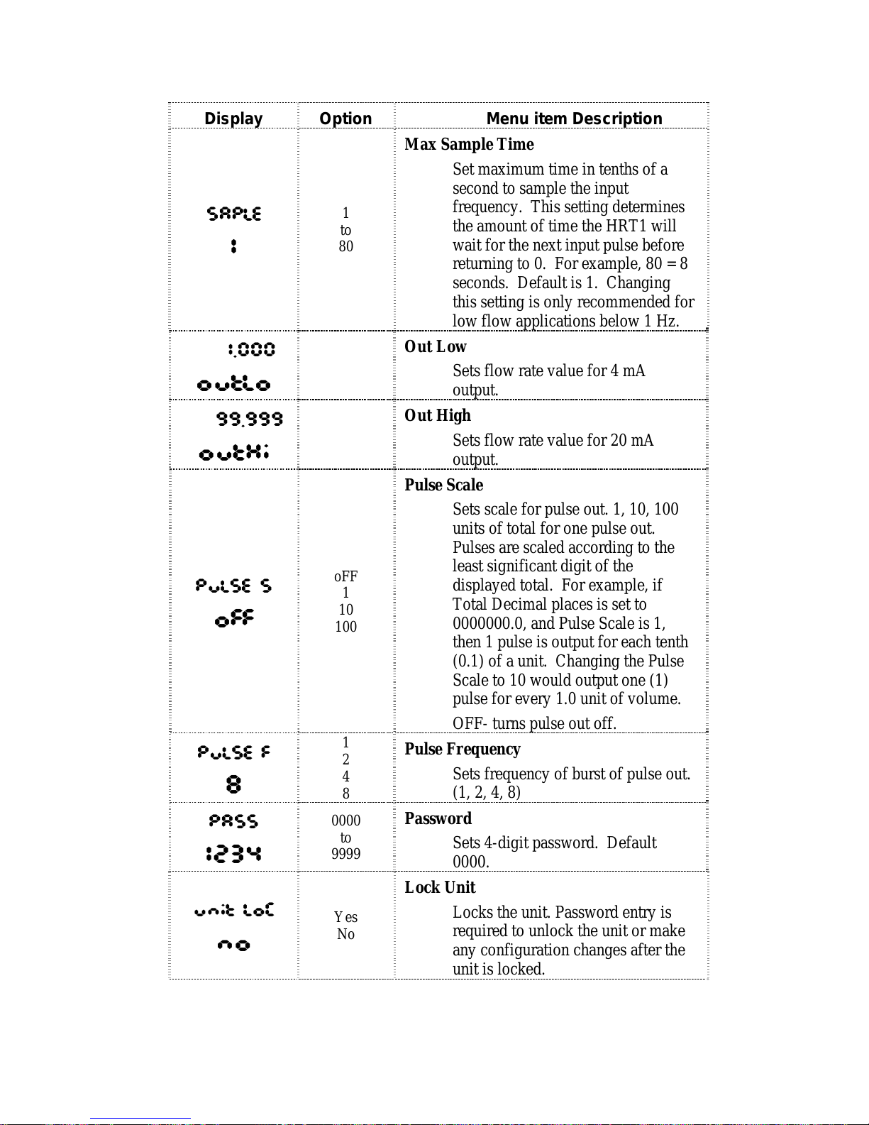
Display Option Menu item Description
SAPLE
1
1
to
80
Max Sample Time
Set maximum time in tenths of a
second to sample the input
frequency. This setting determines
the amount of time the HRT1 will
wait for the next input pulse before
returning to 0. For example, 80 = 8
seconds. Default is 1. Changing
this setting is only recommended for
low flow applications below 1 Hz.
1.000
outLo
Out Low
Sets flow rate value for 4 mA
output.
99.999
outHi
Out High
Sets flow rate value for 20 mA
output.
PuLSE S
oFF
oFF
1
10
100
Pulse Scale
Sets scale for pulse out. 1, 10, 100
units of total for one pulse out.
Pulses are scaled according to the
least significant digit of the
displayed total. For example, if
Total Decimal places is set to
0000000.0, and Pulse Scale is 1,
then 1 pulse is output for each tenth
(0.1) of a unit. Changing the Pulse
Scale to 10 would output one (1)
pulse for every 1.0 unit of volume.
OFF- turns pulse out off.
PuLSE F
8
1
2
4
8
Pulse Frequency
Sets frequency of burst of pulse out.
(1, 2, 4, 8)
PASS
1234
0000
to
9999
Password
Sets 4-digit password. Default
0000.
unit LoC
no
Yes
No
Lock Unit
Locks the unit. Password entry is
required to unlock the unit or make
any configuration changes after the
unit is locked.
Page 30
Configuration 22
HP-313 HRT1
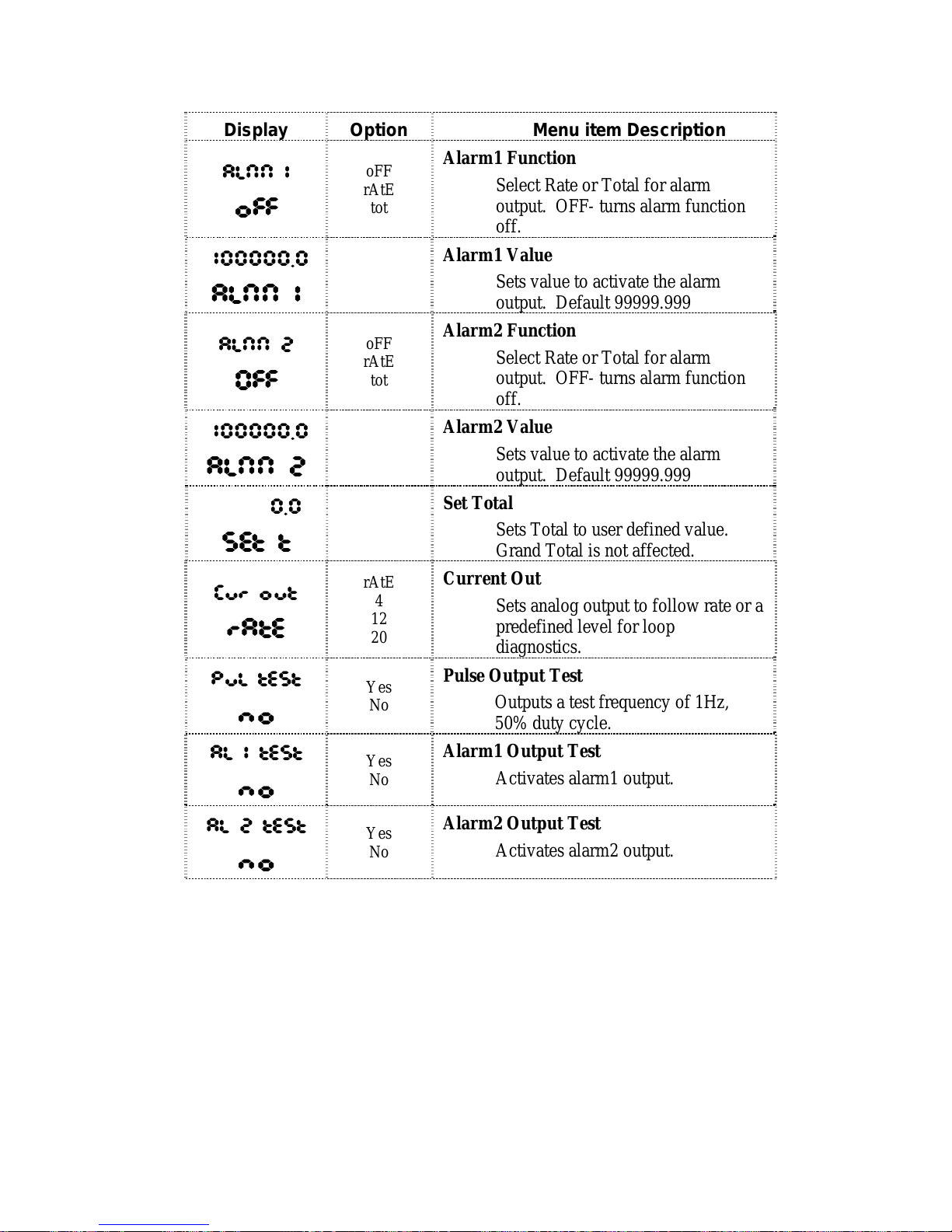
Display Option Menu item Description
ALNN 1
oFF
oFF
rAtE
tot
Alarm1 Function
Select Rate or Total for alarm
output. OFF- turns alarm function
off.
100000.0
ALNN 1
Alarm1 Value
Sets value to activate the alarm
output. Default 99999.999
ALNN 2
OFF
oFF
rAtE
tot
Alarm2 Function
Select Rate or Total for alarm
output. OFF- turns alarm function
off.
100000.0
ALNN 2
Alarm2 Value
Sets value to activate the alarm
output. Default 99999.999
0.0
Set t
Set Total
Sets Total to user defined value.
Grand Total is not affected.
Cur out
rAtE
rAtE
4
12
20
Current Out
Sets analog output to follow rate or a
predefined level for loop
diagnostics.
PuL test
no
Yes
No
Pulse Output Test
Outputs a test frequency of 1Hz,
50% duty cycle.
AL 1 test
no
Yes
No
Alarm1 Output Test
Activates alarm1 output.
AL 2 test
no
Yes
No
Alarm2 Output Test
Activates alarm2 output.
4.2 Default Configuration
HRT1 is fully configured by the factory prior to shipment. When the
instrument is purchased with a Hoffer Flowmeter or when calibration
and configuration data are supplied, the instrument is configured as
specified. When calibration or configuration data is not available, the
instrument is shipped with default values. Refer to Appendix A for a
listing of the HRT1 factory default configuration.
Page 31

Operation and Maintenance 23
HRT1 HP-313
5. OPERATION AND MAINTENANCE
5.1 Display Parameters
The HRT1 calculates and displays total volume and flow rate on a
two-line liquid crystal display (LCD). The top line is an 8-digit Total
Volume display and the bottom is a 5-digit Rate display. The 8-digit
non-resettable Grand Total is also viewed on the top line by
pressing
The Grand Total will be displayed for approximately 15 seconds before
returning to the Total Volume display.
Volume units and the time base for flow rate are indicated by icons on
the right hand side of the LCD. When no icon for time units is
displayed, the time base is /SEC.
A Bar graph located at the bottom of the LCD provides a graphical
representation of the flow rate based on a percentage of the maximum
flow setting.
The flow rate and flow total are calculated and updated on the display
once every 2 seconds.
5.2 Saving Grand Total
To minimize the number of write cycles to non-volatile memory, the
Grand Total is saved once per minute. In the event that both loop
power and battery power are removed simultaneously, the Total will be
lost and the Grand Total could be up to one minute old when restoring
power. When changing the battery (see Section 7 Maintenance), it is
recommended to stop the flow at least two minutes prior to removing
power from the unit to ensure that the stored Grand Total is current
when restoring power.
5.3 Clearing the Total
The Volume Total may be cleared by using a magnet, a contact closure
to power common on the RESET input terminal, from the front panel
keypad or via HART communications (See Chapter 6 HART
Communications).
Page 32

Operation and Maintenance 24
HP-313 HRT1
To clear the total using a magnet, slide the magnet slowly across the
HRT1 model name at the top of the front panel overlay.
To reset the total from the front panel keypad, use the following key
sequence:
Press P CLEArtot is displayed
Press OK To enter edit mode.
Press ▲
To select yes
Press OK To clear total
Press ▲
To return to operating mode
5.4 System Response Time
The displayed Rate and Total are updated every two seconds. The
analog output response time to reach steady state due to a change in the
input is also approximately two seconds.
The time for the display to reach 0 and for the analog output to return to
4 mA when flow stops will be between 3 and 12 seconds, depending on
the Max Sample Time setting (MST). Changing the MST is only
recommended for low flow applications where the input frequency is
below 1 Hz. See Chapter 4 Configuration for more information on
Max Sample Time.
5.5 Error Conditions
The HRT1’s self-checking capability is used to detect and report
malfunctions by displaying error messages on the LCD. When an error
occurs, the display will flash an error message until the error condition
is eliminated, or the user presses the OK button to acknowledge the
condition. Once the error condition has been acknowledged by
pressing OK, the error message will stop flashing. The message will be
displayed again after 60 seconds if the condition that caused the error
has not been resolved. The message will automatically stop flashing
and any associated alarms reset once the error condition is no longer
present.
Page 33

Operation and Maintenance 25
HRT1 HP-313
The following table outlines the detected conditions and recommended
corrective action:
ERROR
MESSAGE
CAUSE
CORRECTIVE
ACTION
EPuLSE
Pulse output exceeds Pulse
Frequency setting. Output
pulses will stop during this
condition.
- Change pulse scale.
- Increase Pulse
Frequency setting(Max
8 Hz).
- Reduce the number
of places after the Total
decimal point.
EErES
EEPROM reset to factory
defaults.
Consult factory
ErAtE
Flow rate exceeds the flow rate
display capability. Displayed
flow rate will consist of all 9s.
Reduce flow rate or
reduce the number of
places after the flow
rate decimal point
EFLo
Flow rate exceeds the 20 mA
max flow setting. Analog
output will saturate at 24 mA.
Reduce flow rate or
increase the 20 mA
max flow setting.
LO BAT
Low battery. Replace battery
5.6 Battery Replacement Indication
The instrument has circuitry designed to monitor the battery voltage
and illuminate a
LO BAT message on the LCD when the battery is
approaching the end of its life.
When changing the battery, it is recommended to stop the flow at least
two minutes prior to removing power from the unit to ensure that the
stored Grand Total is current when restoring power (see section 5.2
Saving Grand Total).
See Section 7 Maintenance for detailed instructions on battery
replacement.
Page 34

Operation and Maintenance 26
HP-313 HRT1
This Page Intentionally Left Blank
Page 35

HART Communications 27
HRT1 HP-313
6. HART COMMUNICATIONS
The HRT1 has been designed to comply with Revision 7.0 of the HART
protocol. A full list of features new to Revision 7.0 may be obtained at
the Hart Communication Foundation website.
A HART Communicator or HART Master may be used to configure,
monitor process variables and obtain diagnostic information from the
HRT1. The instrument must be equipped with the HART Modem
Board (PCA187), which plugs into a 10-pin connector on the backside
of the HRT1 Main Board (PCA186).
Refer to Chapter 3 Installation for information on connections to
HART devices.
HART functions are defined as part of an enhanced device description
language (EDDL). Contact the factory if the HRT1 device is not
available in the list of DD libraries.
6.1 Dynamic Variables
The following Dynamic Variables have been implemented:
Meaning Units
Primary Variable Flow Rate Volume - Gal, Lit, Ft3, M3,
Bbl, Custom
Time
- /Day, /Hour, /Min, /Sec
Secondary Variable Flow Total Follows PV Volume units
Tertiary Variable Grand Total Follows PV Volume units
Quaternary Variable Frequency Hz
The HRT1 may be identified by the following:
Manufacturer ID Code: 224 (E0 Hex)
Device Type Code: 161 (A1 Hex)
Page 36

HART Communications 28
HP-313 HRT1
6.2 Universal Commands
The following Universal Commands have been implemented:
0 Read Unique Identifier
1 Read Primary Variable
2 Read Primary Variable Current and Percent Range
3 Read Dynamic Variables and Primary Variable Current
6 Write Polling Address
7 Read Loop Configuration
8 Read Dynamic Variable Classifications
9 Read Device Variables with Status
11 Read Unique Identifier with Tag
12 Read Message
13 Read Tag Descriptor Date
14 Read Primary Variable Sensor Info
15 Read Primary Variable Output Info
16 Read Final Assembly Number
17 Write Message
18 Write Tag Descriptor Date
19 Write Final Assembly Number
20 Read Long Tag
21 Read Unique identifier with Long Tag
22 Write Long Tag
6.3 Common-Practice Commands
The following Common-Practice Commands have been implemented:
35 Write Range Values
38 Reset "Configuration Changed" Flag
40 Enter/Exit Fixed Current Mode
42 Perform Master Reset
45 Trim DAC Zero
46 Trim DAC Gain
48 Read Additional Device Status
Page 37

HART Communications 29
HRT1 HP-313
6.4 Device-Specific Commands
The following Device-Specific Commands have been implemented:
#
COMMAND DESCRIPTION
128
Read Decimal Point
Location
Read the decimal point location
for Rate and Total.
129
Write Rate Decimal Point
Location
Select displayed flow rate
resolution as 00000, 0000.0,
000.00 or 00.000.
130
Write Total Decimal Point
Location
Select displayed total resolution
as 00000000, 0000000.0,
000000.00 or 00000.000.
131
Clear Total Reset the Total to zero.
132
Set Total Set the Total to a user defined
value.
133
Read Linearization
Variables
Read the flowmeter linearization
parameters
.
134
Write Linearization Set flowmeter linearization
method as Average K-Factor or
Linearization Table.
135
Write K-Factor Decimal
Point
Select k-factor resolution as
00000000, 0000000.0,
000000.00 or 00000.000.
136
Write Average-K Factor Write the value of the Average
K-Factor. Valid entries are
between 0.001 and 99999999.
137
Write Number of Points Write the number of points in
the Linearization Table. 20 is
the max number of points.
138
Write Correction Factor Write the value of the Correction
Factor. The correction factor is
a multiplier used to correct flow
rate and total.
139 Read Linearization Table Read the flowmeter
Linearization Table.
140 Write Linearization
Frequency
Write the Frequency values for
the linearization table points.
Page 38

HART Communications 30
HP-313 HRT1
#
COMMAND DESCRIPTION
141 Write Linearization
K-Factor
Write the K-Factor values for the
linearization table points.
142 Read Pulse Information Read Pulse Scale and Pulse
Frequency information.
143 Write Pulse Scale Set the Pulse Scale to 1, 10, 100
or OFF.
144 Write Pulse Frequency Set the frequency in Hz. of the
pulse output burst to 1, 2, 4 or 8.
145 Pulse Output Control Stop 1 Hz Pulse Output Test.
146 Pulse Output Test Start 1Hz Pulse Output Test.
147 Read Alarm Info Read Function and Level for
Alarm 1 and 2.
148 Write Alarm Function Define the function of the Alarm
Output as Rate or Total.
149 Write Alarm Level Write the value at which an
alarm condition is indicated.
150 Alarm Release Release the Alarm Output test.
151 Alarm Test Activate Alarm Output.
152 Read Tag Read Tag Number.
153 Write Tag Write Tag Number. 0 to
99999999.
154 Read Sample Time Read Sample Time.
155 Write Sample Time Write Sample Time. Valid
entries 1-80.
156 Write Password Write 4-digit password. 9999 is
max value.
157 Read Lock Status Read Lock Status. Password is
required when unit is locked.
158 Write Lock Unit Lock the unit and enable
password protection.
159 Read Current Mode Read mode for analog output
current (4mA, 12mA, 20mA,
Follows Rate).
Page 39

HART Communications 31
HRT1 HP-313
#
COMMAND DESCRIPTION
160 Write Current Mode Write mode for analog output
current (4mA, 12mA, 20mA,
Follows Rate).
161 Read Units Read units for volume total and
rate.
162 Write Flow Rate Time Write units for flow rate time
base (/Sec, /Min, /Hr, /Day).
163 Write Total Units Write units for volume total
(GAL, FT3, L, M3, BBL).
6.5 Device Status
The following Status Bits are implemented:
Bit 0 - Primary Variable Out Of Limits
Bit 1 - Non-Primary Variable Out Of Limits
Bit 2 - Primary Variable Analog Output Saturated
Bit 3 - Primary Variable Analog Output Fixed
Bit 4 - More Status Available
Bit 5 – Cold Start
Bit 6 – Configuration Changed
Bit 7 – Device Malfunction
Page 40

HART Communications 32
HP-313 HRT1
6.6 Additional Device Status
The following Additional Device Status Bits are implemented:
Byte Bit Meaning
0 Unused
1 Unused
2 Pulse Output Overflow
3 Flow Over range
4 Flow Rate Display Too High
5 DAC Zero Not Calibrated
6 DAC Gain Not Calibrated
0
7 Bit Current Override
0 Total Units Error
1 Rate Time Units Error
2 Linearization Function Error
3 K-Factor Decimal Point Error
4 Number of Points Error
5 Total Decimal Point Error
6 Rate Decimal Point Error
1
7 Sample Time Error
0 Unused
1 Unused
2 Unused
3 Pulse Scale Error
4 Pulse Frequency Error
5 Unit Locked
6 Alarm 2 Function Error
2
7 Alarm 1 Function Error
Page 41

HART Communications 33
HRT1 HP-313
Byte Bit Meaning
0 Unused
1 Unused
2 Unused
3 Unused
4 Unused
5 Pulse Output Test
6 Alarm 2 Test
3
7 Alarm 1 Test
0 Unused
1 Unused
2 Unused
3 Unused
4 Unused
5 Unused
6 Alarm 2 Activated
4
7 Alarm 1 Activated
0 Unused
1 Unused
2 Unused
3 Unused
4 Unused
5 Unused
6 Unused
5
7 Unused
0 Maintenance Required
1 Device Variable Alert
2 Critical Power Failure
3 Unused
4 Unused
5 Unused
6 Unused
6
7 Unused
Page 42

HART Communications 34
HP-313 HRT1
Byte Bit Meaning
0 Unused
1 Unused
2 Unused
3 Unused
4 Unused
5 Unused
6 Unused
7
7 Unused
0 Simulation Active
1 Non-Volatile Memory Defect
2 Volatile Memory Defect
3 Watchdog Reset Executed
4 Voltage Conditions Out of Range
5 Environment Conditions Out of
6 Electronic Defect
8
7 Unused
Page 43

HART Communications 35
HRT1 HP-313
6.7 EDDL – Process Variables
Primary Variables
Flow Rate – Display of currently measured volumetric flow
with units selected.
Flow Rate Loop Current – Display of current value of
analog output (4-20 mA) based on flow rate.
Flow Rate % rnge – Display of current % of flow rate range.
Flow Rate LRV – Display of Lower Range Value for 4 mA
flow setting.
Flow Rate URV – Display of Upper Range Value for 20 mA
flow setting.
Total – Display of currently measured volumetric flow total
with units selected.
Grand Total - Display of currently measured grand total with
units selected.
Frequency – Display of currently measured flowmeter input
frequency in Hz
Identification
Tag – Assign HART Tag to device
Long Tag – Assign long HART Tag to device
Manufacturer – Display HOFFER FLOW CNTRLS
Model – Display HRT1
Dev id – Display ID number associated with device.
PV Snsr s/n – Display of serial number for Primary
Variable sensor.
Page 44

HART Communications 36
HP-313 HRT1
6.8 EDDL – Device Diagnostics
Warning
Alarm 1 Being Tested – Indicates Alarm Output 1 is in test
mode.
Alarm 2 Being Tested – Indicates Alarm Output 2 is in test
mode.
Pulse Output Being Tested – Indicates Pulse Output is in test
mode.
Alarm 1 Activated – Indicates an alarm has occurred in
response to a condition assigned to Alarm 1 output.
Alarm 2 Activated – Indicates an alarm has occurred in
response to a condition assigned to Alarm 2 output.
Flow Rate Exceeds Display - Flow rate exceeds the flow rate
display capability. Displayed as
ErAtE on the HRT1 LCD
display. See section 5.5 Error Conditions for more
information.
Flow Exceeds 20 mA Calibration - Flow rate exceeds the 20
mA flow rate upper range value (URV). Analog output will
saturate at 24 mA. Displayed as
EFLo on the HRT1 LCD
display. See section 5.5 Error Conditions for more
information.
Pulse Rate Overflow - Pulse output exceeds Pulse Frequency
setting. Output pulses will stop during this condition.
Displayed as
EPuLSE on the HRT1 LCD display. See
section 5.5 Error Conditions for more information.
6.9 EDDL – Online
Device Setup
HRT1 Tag – Assign HRT1 serial number
Max Sample Time – Assign the maximum time in tenths of a
second to sample the input frequency. This setting determines
the amount of time the HRT1 will wait for the next input pulse
before returning to 0. Valid entry is 1-80, with 80 = 8
seconds. Default is 1. Changing this setting is only
recommended for low flow applications below 1 Hz. See
section 4.1 Local Configuration for more information.
Page 45

HART Communications 37
HRT1 HP-313
Change Lock Status – Enable password protection by
selecting YES, disable by selecting NO.
Password – Assign a 4-digit password.
Flow Setup
Rate Units – Select SECONDS, MINUTES, HOURS or
DAYS for flow rate units.
Lower Flow Rate for 4 mA output (LRV) – Assign flow rate
for 4 mA output.
Upper Flow Rate for 20 mA output (URV) – Assign flow
rate for 20 mA output.
Rate Decimal Point – Select displayed flow rate resolution as
00000, 0000.0, 000.00 or 00.000.
Total Setup
Clear Total – Select YES to clear Total (Grand Total is non-
resettable)
Set Total – Write a specific value to Total.
Units – Select L, M3, GAL, BBL, FT3 OR
“BLANK”(custom) for Total units.
Total Decimal Point – Select displayed total resolution as
00000000, 0000000.0, 000000.00 or 00000.000.
Outputs Setup
Pulse Output
Pulse Scale – Select OFF, 1, 10 or 100. Pulses are scaled
according to the least significant digit of the displayed total.
For example, if Total Decimal places is set to 0000000.0, and
Pulse Scale is 1, then 1 pulse is output for each tenth (0.1) of a
unit. Changing the Pulse Scale to 10 would output one (1)
pulse for every 1.0 unit of volume. OFF turns Pulse Output
off.
Page 46

HART Communications 38
HP-313 HRT1
Pulse Frequency – Select 1, 2, 4 or 8 to select the frequency
in Hz. of the pulse output burst.
Pulse Test – Outputs a test frequency of 1 Hz / 50% duty
cycle on the pulse output terminals.
Analog Setup
Current Mode – Select FOLLOWS RATE or SET TO 4 mA,
12 mA, or 20 mA.
D/A trim – Calibrate the analog output 4 mA and 20 mA
reading with a reference meter connected.
Loop Test – Set analog output to fixed mode by selecting 4
mA, 20 mA or OTHER.
Alarm 1
Alarm 1 Function – Select TOTAL, RATE or OFF.
Alarm 1 Out – Numeric entry to assign an alarm threshold.
Set Alarm 1 ON – Toggle Alarm 1 Output to test.
Alarm 2
Alarm 2 Function – Select TOTAL, RATE or OFF.
Alarm 2 Out – Numeric entry to assign an alarm threshold.
Set Alarm 2 ON – Toggle Alarm 2 Output to test.
Meter Setup
Linearization – Select AVERAGE K-FACTOR to use a
single K-Factor or LINEARIZATION TABLE to enter up to
20 points.
K-Factor Decimal Point Location - Select k-factor resolution
as 00000000, 0000000.0, 000000.00 or 00000.000
Page 47

HART Communications 39
HRT1 HP-313
Number of Points in Table – Select the number of points (1-
20) in the table when LINEARIZATION TABLE is selected.
Frequency/K-Factor – Enter Frequency and K-Factors for
each point in table.
Average K-Factor – Enter Average K-Factor when
AVERAGE K-FACTOR is selected for Linearization.
Correction Factor – User defined flow total multiplier
between 0.001 and 99999.999.
HART Setup
Poll Addr – (Polling address) Assign a number between 0-15
to be used in multidrop applications.
Date – Enter the Date
Descriptor – Enter a descriptor
Message – Enter a message
Final asmbly num – Enter Assembly number.
Page 48

HART Communications 40
HP-313 HRT1
This Page Intentionally Left Blank
Page 49

Appendix A – Default Configuration 41
HRT1 HP-313
7. MAINTENANCE
The only maintenance for the HRT1 is a possible battery replacement
after several years in service.
All configuration settings are stored in nonvolatile memory; therefore,
configuration settings will not be lost in the event of battery failure.
Lithium Battery Pack Replacement
WARNING: To prevent ignition of hazardous atmospheres, do
not remove the cover unless the area is void of combustible gas
and vapors. Replace the batteries only with battery part
number 100-2732 for Ex systems.
WARNING: The lithium battery that powers the HRT1 is a
sealed unit; however, should Lithium batteries develop a leak,
toxic fumes could escape upon opening the enclosure. Ensure
that the instrument is in a well-ventilated area before opening
the enclosure to avoid breathing fumes trapped inside the
enclosure. Exercise caution in handling and disposing of spent
or damaged batteries.
Important: Before replacing the lithium battery stop the flow
for at least two minutes prior to removing power from the unit
to ensure that the stored Grand Total is current when
restoring power. See Section 5.2 Saving Grand Total.
The lithium battery is secured inside the enclosure by a Velcro straps
and connected to a connector (JP2) near the top of the circuit assembly.
To replace a lithium battery pack in the HRT1, perform the following
steps:
Ex Proof Enclosure:
1. Loosen the cover set screw and unscrew the cover of the enclosure
counter-clockwise until it separates from the main body of the
enclosure.
2. Using a small standard blade screwdriver, remove the two #4-40
screws located to the lower right and upper left side of the LCD
display.
Page 50

Appendix A – Default Configuration 42
HP-313 HRT1
3. Lift the display/keypad assembly from the enclosure, making sure
the circuit assembly does not contact the enclosure.
4. Loosen the Velcro straps, disconnect the battery from the JP2
connector on the circuit assembly, and remove the battery from
the enclosure.
5. Install the new battery in the enclosure in the same position as the
original battery, and secure the Velcro straps tightly around the
battery.
6. Connect the replacement battery to the JP2 connector.
7. Place the circuit assembly over the standoffs and fasten with the
two #4-40 screws, ensuring that all connector wiring is inside the
enclosure.
8. Replace the enclosure cover, threading it onto the enclosure in a
clockwise direction.
NEMA Enclosure:
1. Loosen, by turning counter-clockwise, the screws in each corner of
the enclosure cover to remove.
2. Remove four #4-40 screws from the front panel by turning
counter-clockwise.
3. Lift the display assembly from the enclosure.
4. Loosen the Velcro strap, disconnect the battery from the JP2
connector on the circuit assembly, and remove the battery from the
enclosure.
5. Install the new battery in the enclosure in the same position as the
original battery, and secure the Velcro tightly around the battery.
6. Connect the replacement battery to the JP2 connector.
7. Replace the display assembly and enclosure cover.
Battery shelf life is estimated at 10 years at a storage temperature of 25° C.
Page 51

Appendix A – Default Configuration 43
HRT1 HP-313
APPENDIX A – Default Configuration
Factory default configuration:
FIELD Value
TAG 10000000
LINEARIZATION
METHOD
Average
K-FACTOR DECIMAL
LOCATION
3
AVERAGE K-FACTOR 1.00
NUMBER OF POINTS 20
FREQUENCY 01 4999.981
FREQUENCY 02 4999.982
FREQUENCY 03 4999.983
FREQUENCY 04 4999.984
FREQUENCY 05 4999.985
FREQUENCY 06 4999.986
FREQUENCY 07 4999.987
FREQUENCY 08 4999.988
FREQUENCY 09 4999.989
FREQUENCY 10 4999.990
FREQUENCY 11 4999.991
FREQUENCY 12 4999.992
FREQUENCY 13 4999.993
FREQUENCY 14 4999.994
FREQUENCY 15 4999.995
FREQUENCY 16 4999.996
FREQUENCY 17 4999.997
FREQUENCY 18 4999.998
FREQUENCY 19 4999.999
FREQUENCY 20 5000.000
K-FACTOR 01 1.00
K-FACTOR 02 1.00
K-FACTOR 03 1.00
K-FACTOR 04 1.00
K-FACTOR 05 1.00
K-FACTOR 06 1.00
K-FACTOR 07 1.00
K-FACTOR 08 1.00
K-FACTOR 09 1.00
K-FACTOR 10 1.00
K-FACTOR 11 1.00
K-FACTOR 12 1.00
Page 52

Appendix A – Default Configuration 44
HP-313 HRT1
K-FACTOR 13 1.00
K-FACTOR 14 1.00
K-FACTOR 15 1.00
K-FACTOR 16 1.00
K-FACTOR 17 1.00
K-FACTOR 18 1.00
K-FACTOR 19 1.00
K-FACTOR 20 1.00
CORRECTION FACTOR 1.000
TOTAL UNITS 100 (GAL)
RATE UNITS MINUTES
MAX SAMPLE TIME 01
OUT LOW (LRV–4MA) 00000.000
OUT HIGH (URV–20 MA) 99.999
PULSE SCALE 0 (OFF)
PULSE FREQENCY 8
ALARM 1 FUNCTION Off
ALARM 1 SETPOINT 99999.981
ALARM 2 FUNCTION Off
ALARM 2 SETPOINT 99999.981
CURRENT OUT FOLLOWS RATE
PULSE TEST No
ALARM 1 TEST No
ALARM 2 TEST No
Page 53

Appendix B – Declaration of Conformity 45
HRT1 HP-313
APPENDIX B – Declaration of Conformity
Page 54

Appendix B – Declaration of Conformity 46
HP-313 HRT1
Page 55

Appendix C – Installation Drawings and Conditions 47
for Safe Use for Certified Systems
HRT1 HP-313
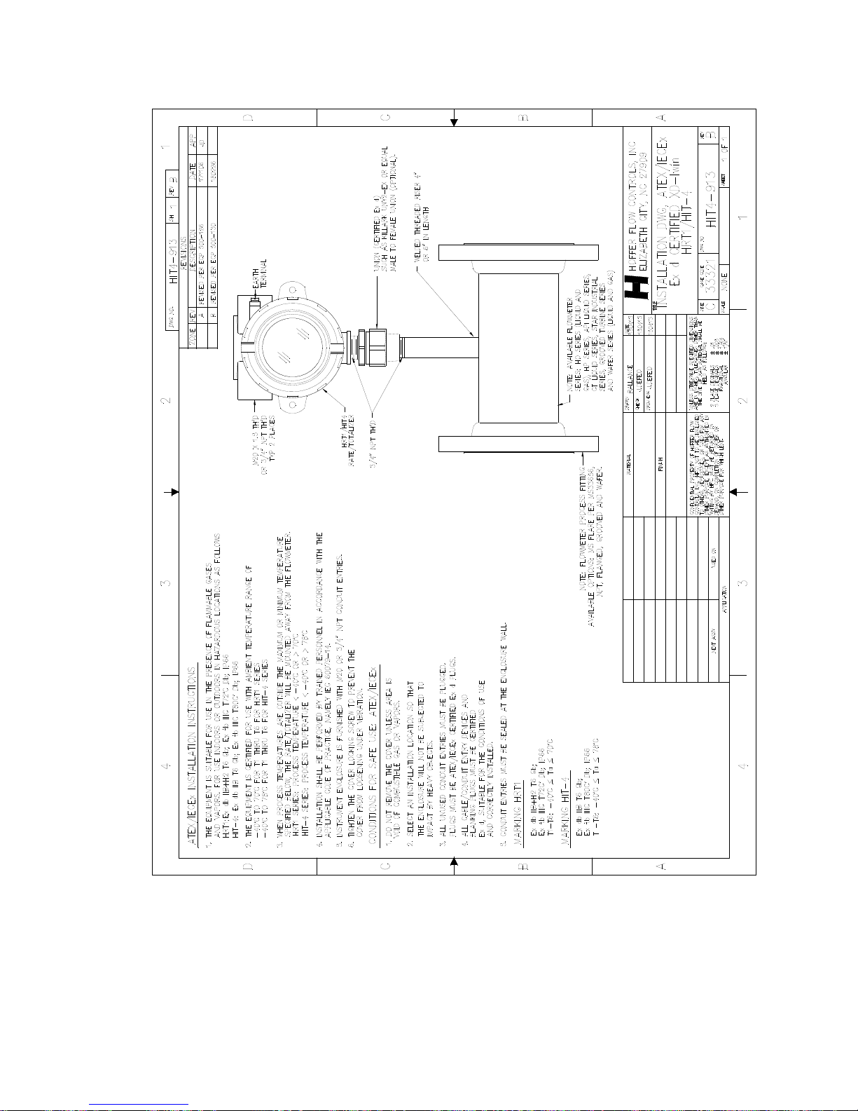
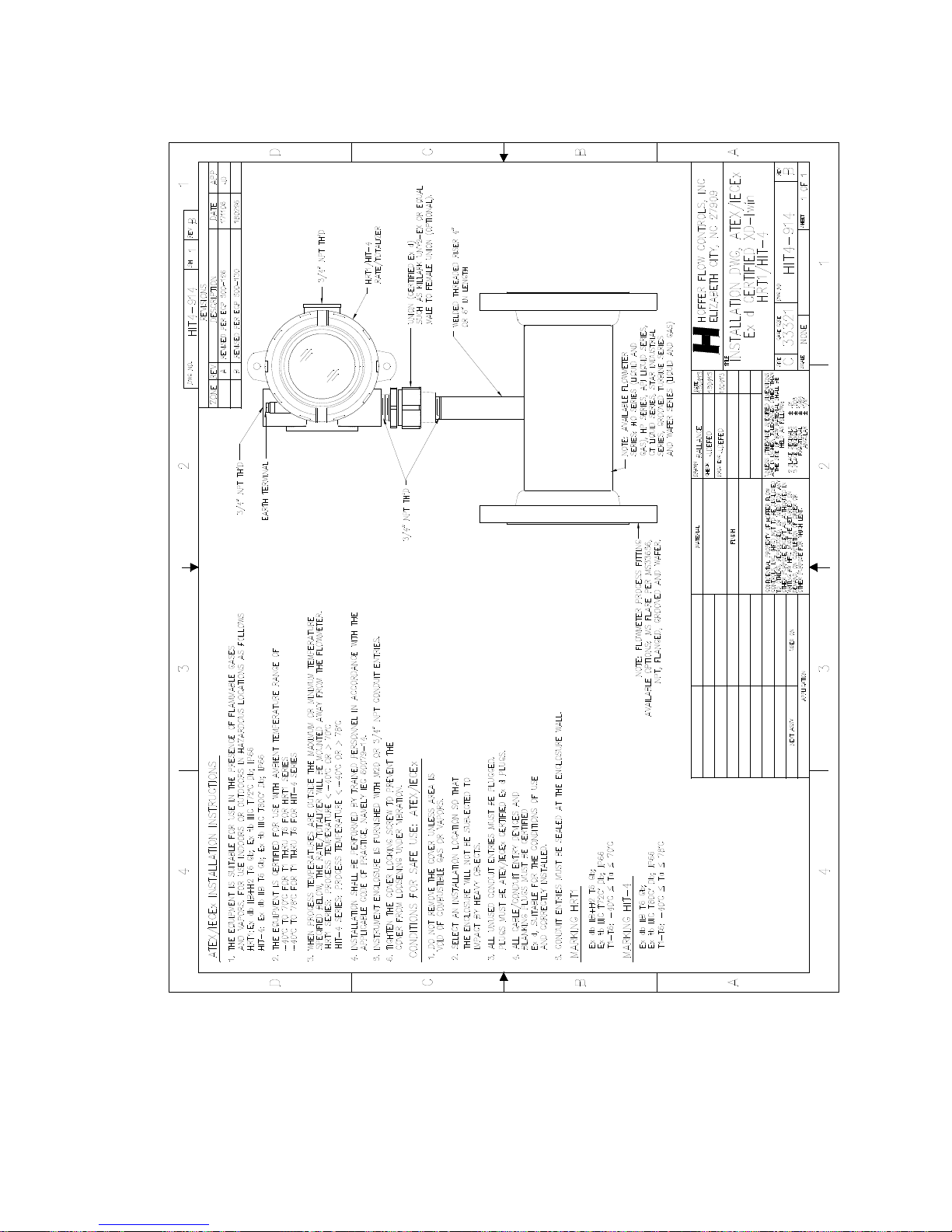
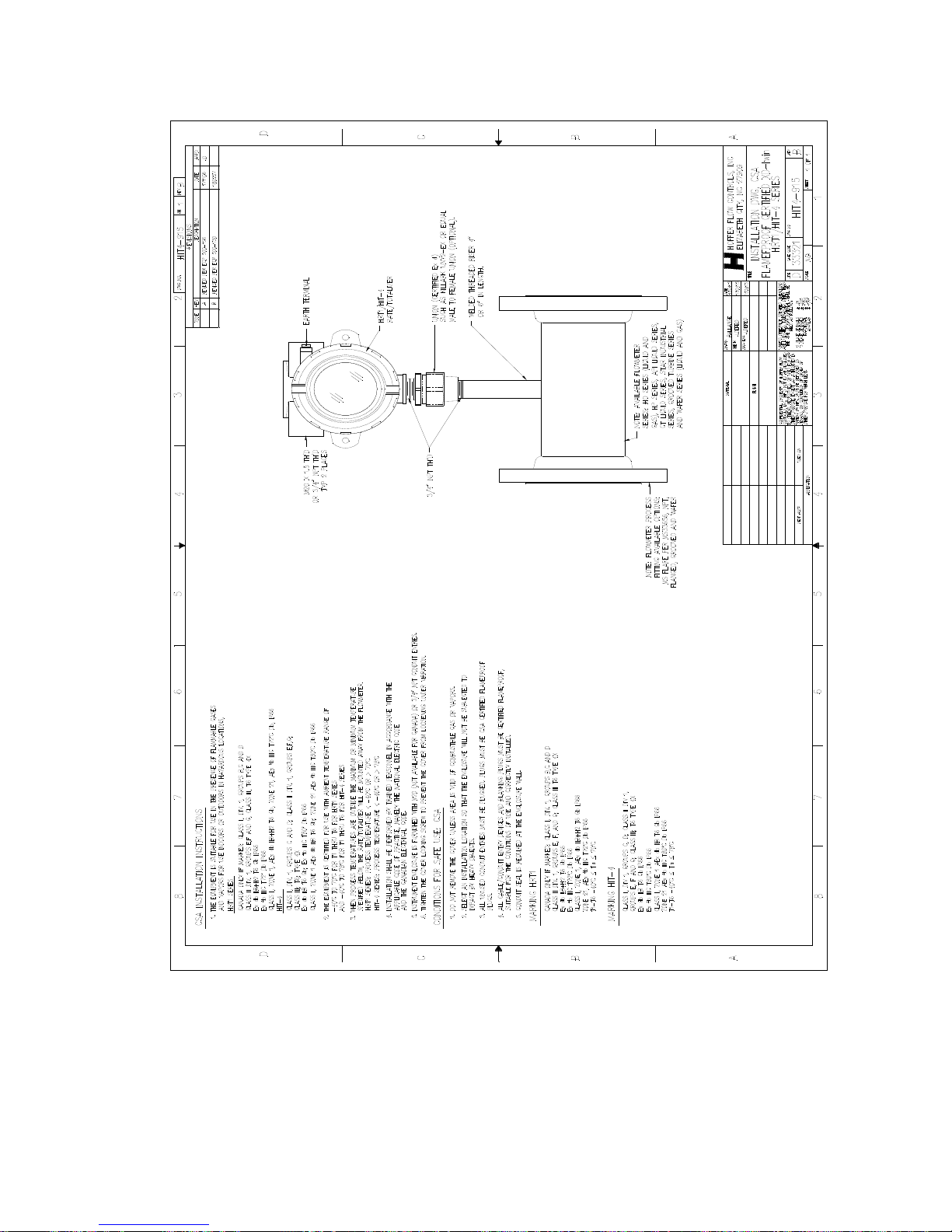
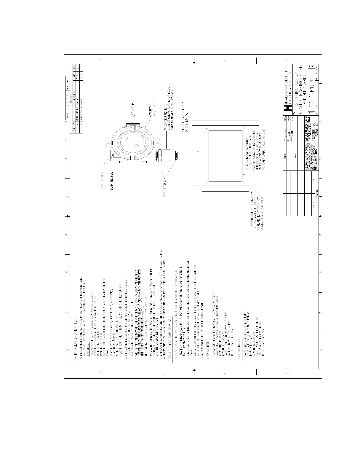
APPENDIX C
Installation Drawings and Conditions for Safe Use for
Certified Systems
Page 56
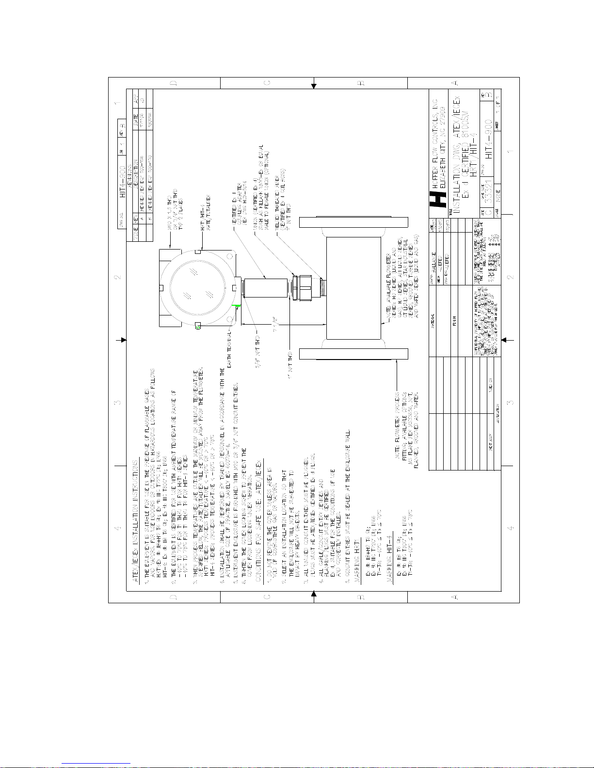
48 Appendix C – Installation Drawings and Conditions
for Safe Use for Certified Systems
HP-313 HRT1
Page 57
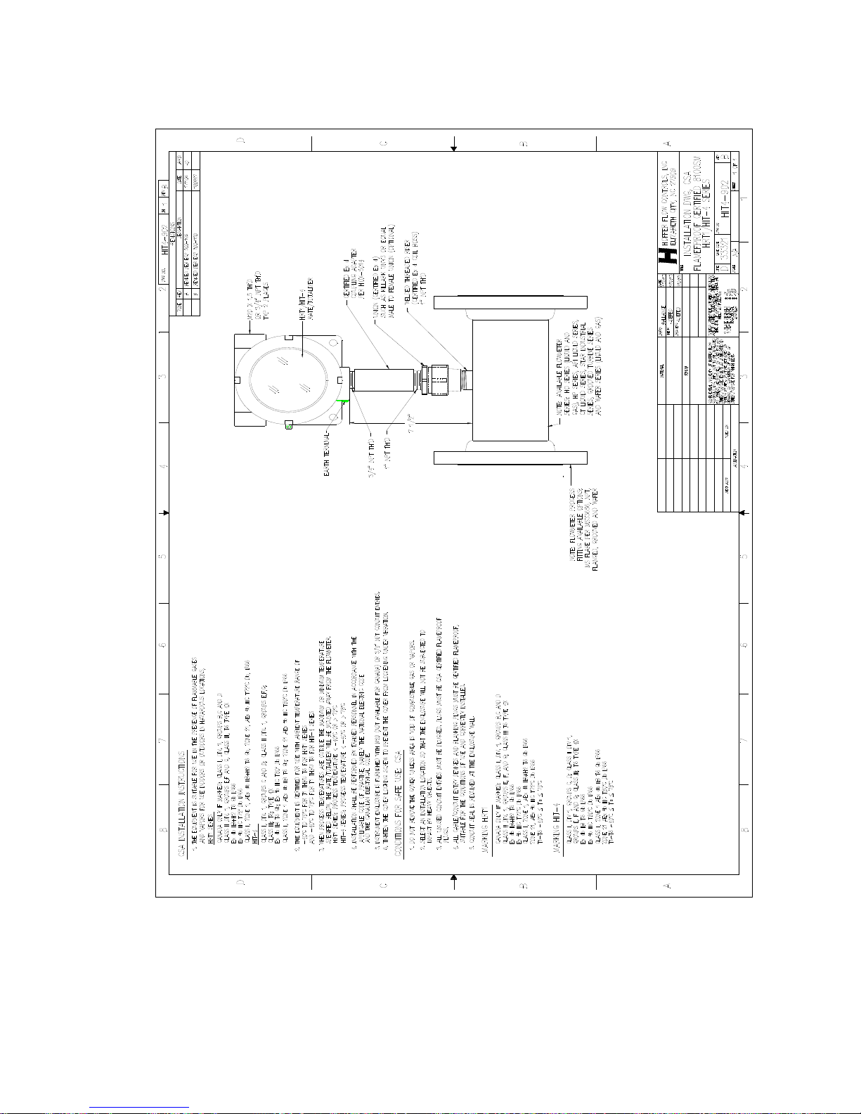
Appendix C – Installation Drawings and Conditions 49
for Safe Use for Certified Systems
HRT1 HP-313
Page 58
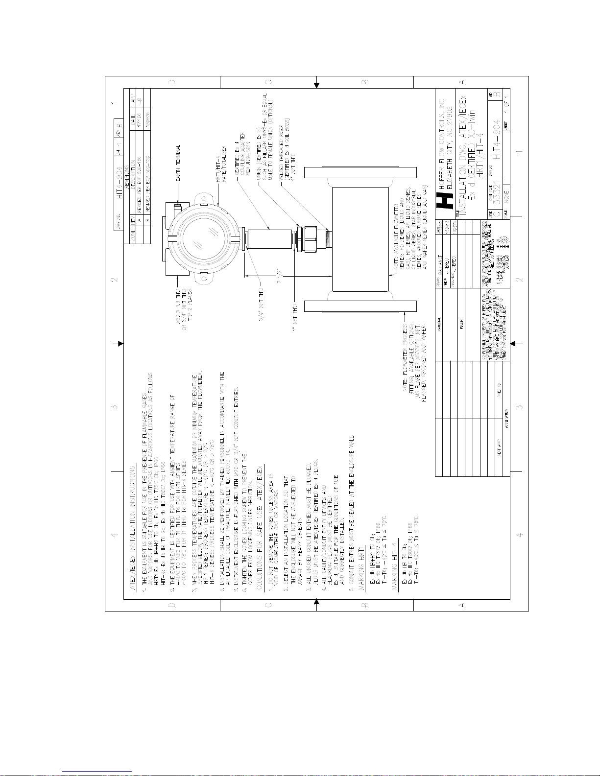
50 Appendix C – Installation Drawings and Conditions
for Safe Use for Certified Systems
HP-313 HRT1
Page 59
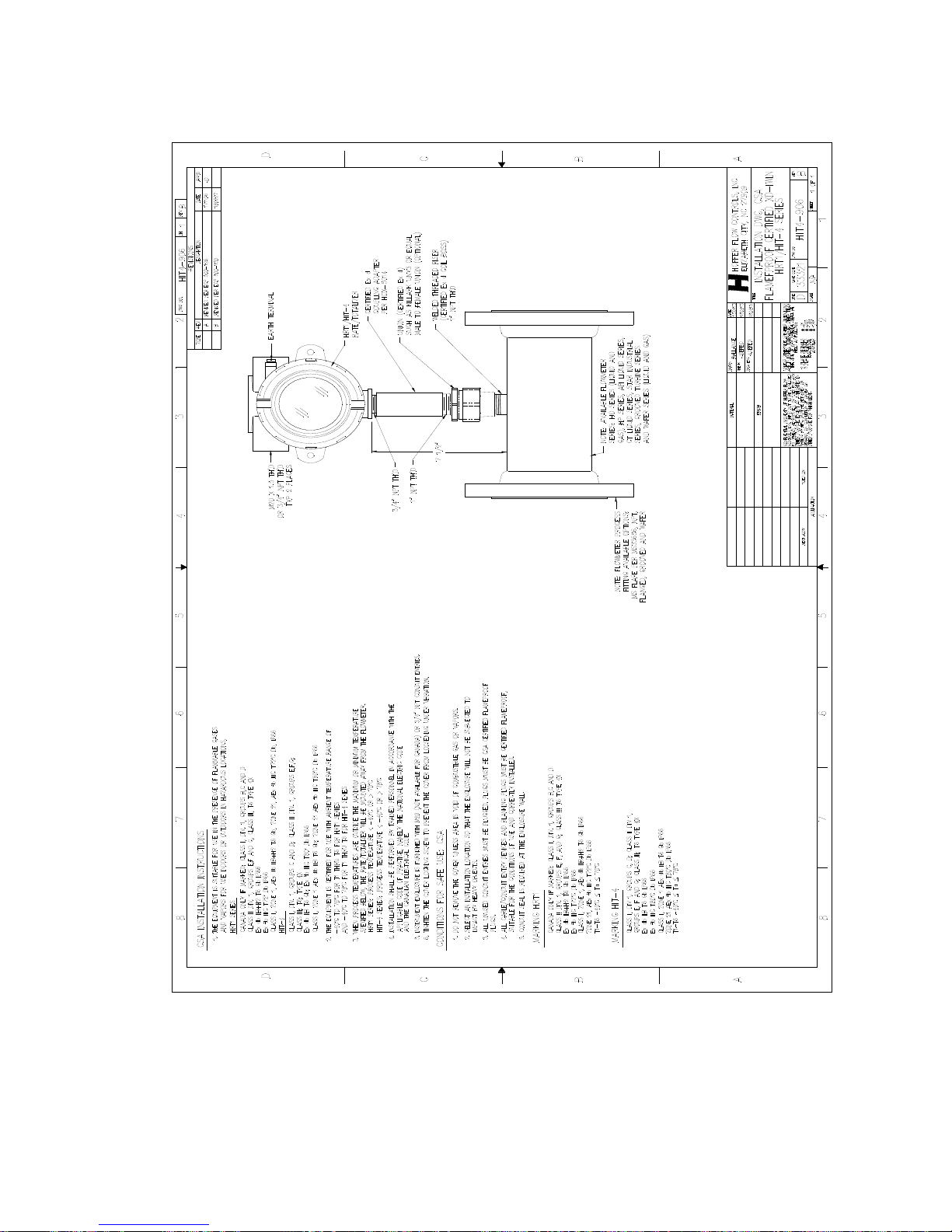
Appendix C – Installation Drawings and Conditions 51
for Safe Use for Certified Systems
HRT1 HP-313
Page 60
52 Appendix C – Installation Drawings and Conditions
for Safe Use for Certified Systems
HP-313 HRT1
Page 61
Appendix C – Installation Drawings and Conditions 53
for Safe Use for Certified Systems
HRT1 HP-313
Page 62
54 Appendix C – Installation Drawings and Conditions
for Safe Use for Certified Systems
HP-313 HRT1
Page 63
Appendix C – Installation Drawings and Conditions 55
for Safe Use for Certified Systems
HRT1 HP-313
Page 64

56 Appendix C – Installation Drawings and Conditions
for Safe Use for Certified Systems
HP-313 HRT1
Page 65
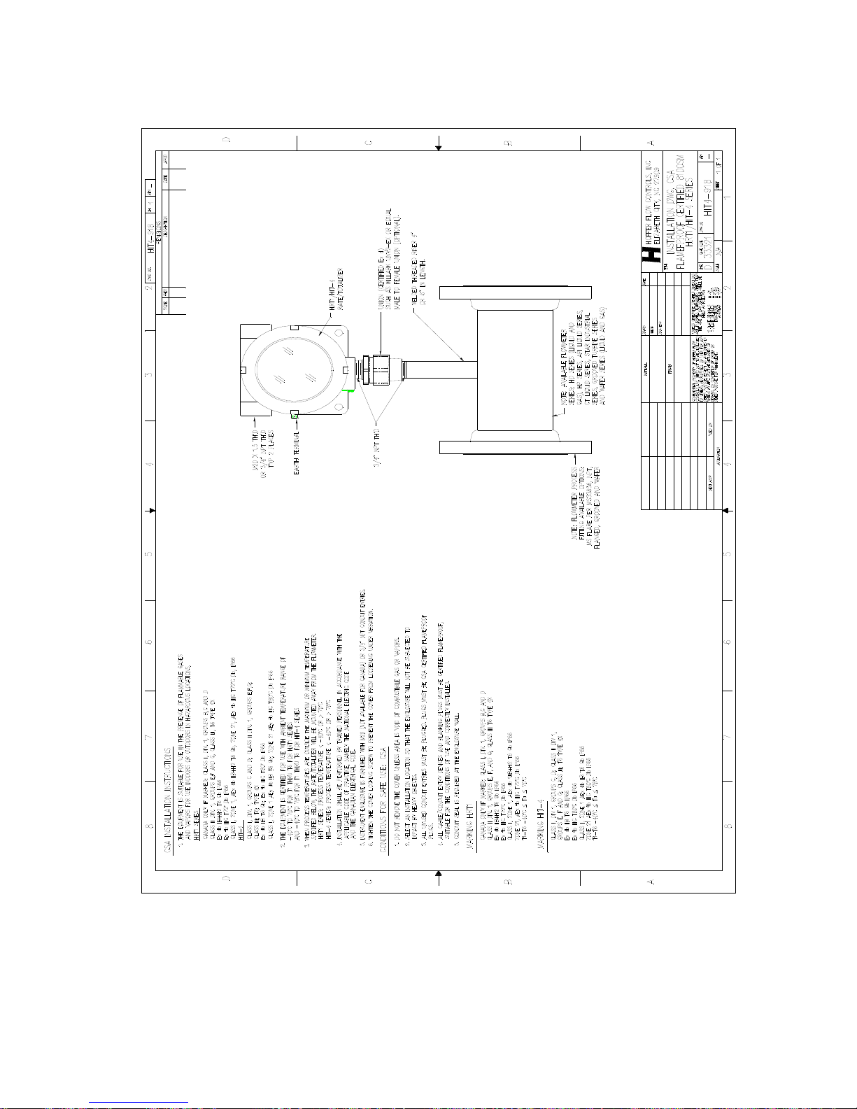
Appendix C – Installation Drawings and Conditions 57
for Safe Use for Certified Systems
HRT1 HP-313
Page 66
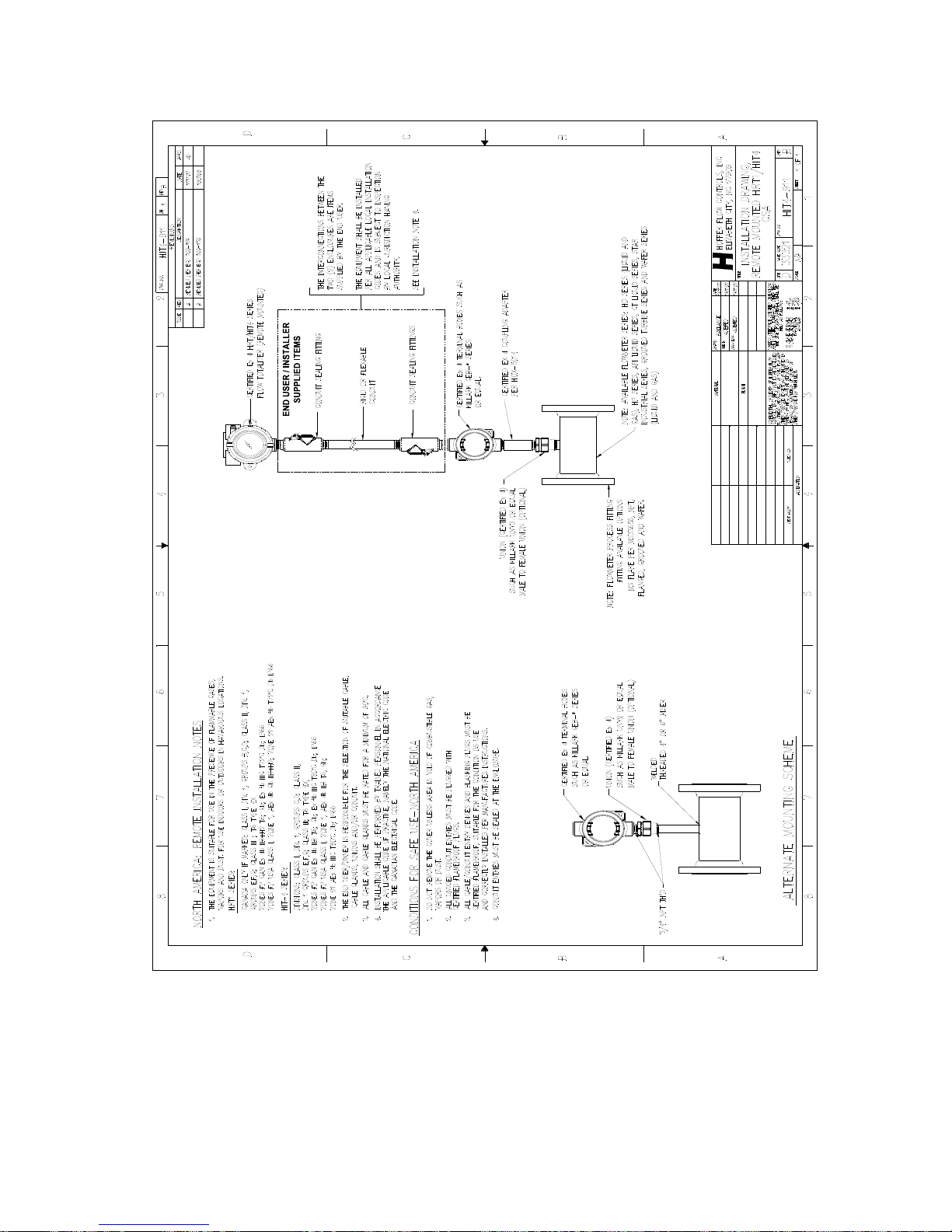
58 Appendix C – Installation Drawings and Conditions
for Safe Use for Certified Systems
HP-313 HRT1
Page 67
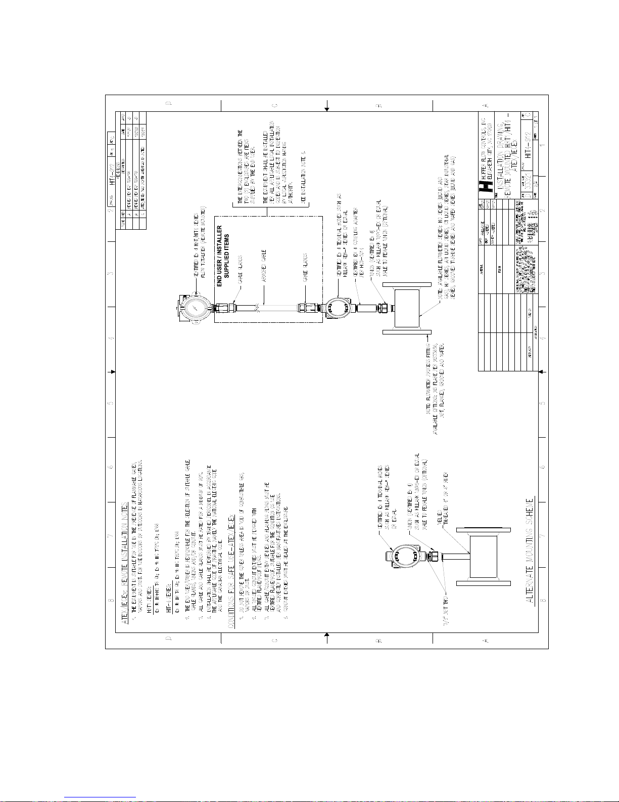
Appendix C – Installation Drawings and Conditions 59
for Safe Use for Certified Systems
HRT1 HP-313
 Loading...